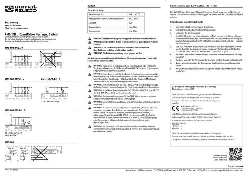
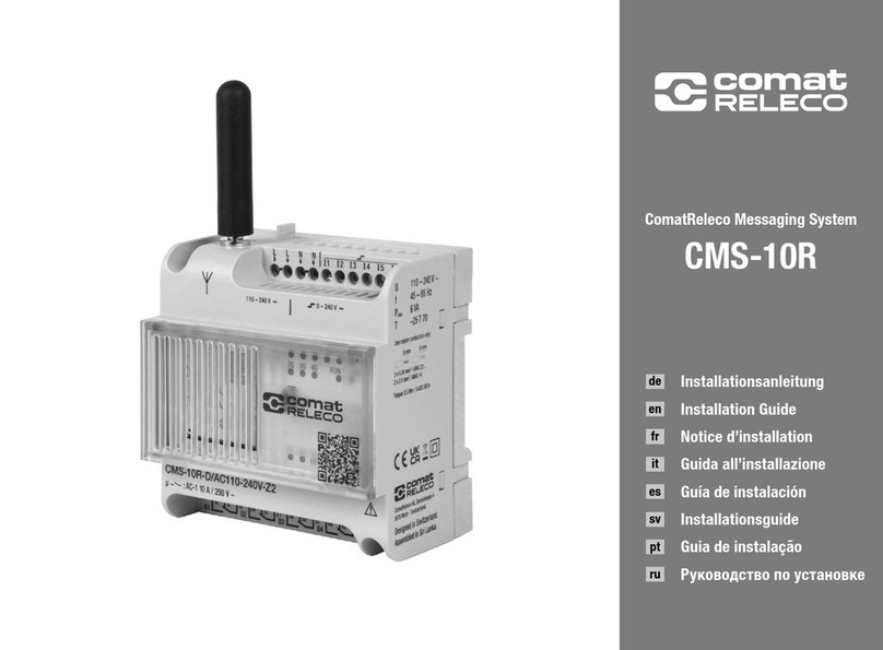
Comat Releco CMS-10R Series User manual

ComatReleco Messaging System
CMS-10R
User Manual

TABLE OF CONTENTS
USER MANUAL CMS-10R | 2
1!Validity..........................................................................................................................................................................4!
2 Safety............................................................................................................................................................................5
2.1 Meaning of symbols...............................................................................................................................................5
2.2 Warnings ...............................................................................................................................................................5
2.3 Installation instructions ..........................................................................................................................................7
2.4 User group .............................................................................................................................................................7
2.5 Intended use ..........................................................................................................................................................7
2.6 Disclaimer..............................................................................................................................................................7
3!Product description......................................................................................................................................................8!
3.1!Overview................................................................................................................................................................8!
3.2!Product variants.....................................................................................................................................................9!
10.1!Hardware description...........................................................................................................................................10!
10.2!Applications .........................................................................................................................................................14!
10.3!Country versions ..................................................................................................................................................14!
10.4!Supported frequency bands .................................................................................................................................14!
10.5!Network coverage................................................................................................................................................14!
10.6!Functions and communication channels...............................................................................................................15!
10.6.1 App..............................................................................................................................................................16
10.6.2 Push messages ...........................................................................................................................................16
10.6.3 E-mail messages.........................................................................................................................................16
10.6.4 SMS messages............................................................................................................................................16
10.6.5 Escalation chain ..........................................................................................................................................16
10.6.6 Relay outputs switch via the app..................................................................................................................17
10.6.7 Relay outputs switch via a call.....................................................................................................................17
10.6.8 Relay outputs switch via SMS ......................................................................................................................17
10.6.9 Periodic messages.......................................................................................................................................17
10.6.10 Message on loss of mobile connection.........................................................................................................17
10.6.11 Message when mobile phone connection is regained...................................................................................17
10.6.12 Message in case of supply voltage failure ....................................................................................................18
10.6.13 Message when supply voltage is switched on..............................................................................................18
10.6.14 Failure of the IoT portal (fallback).................................................................................................................18
11!Installing the device...................................................................................................................................................19!
11.1!Mounting .............................................................................................................................................................19!
11.1.1!Mounting the device ....................................................................................................................................19!
11.1.2!Dismantling the device ................................................................................................................................19!
11.2!Wiring ..................................................................................................................................................................19!
11.2.1!Power supply...............................................................................................................................................19!
11.2.2!Wiring CMS-10R/D ......................................................................................................................................20!
11.2.3!Wiring CMS-10R/DA ....................................................................................................................................20!
11.2.4!Wiring CMS-10R/DAC ..................................................................................................................................20!
11.2.5!Wiring CMS-10R/D/DA/DAC .........................................................................................................................20!
11.3!Antennas .............................................................................................................................................................21!
12!IoT portal ....................................................................................................................................................................22!
12.1!Introduction..........................................................................................................................................................22!
12.2!Initial commissioning ...........................................................................................................................................23!

TABLE OF CONTENTS
USER MANUAL CMS-10R | 3
12.3!Device configuration ............................................................................................................................................24!
12.3.1!Adding a new device....................................................................................................................................25!
12.3.2!Pairing a new device....................................................................................................................................28!
12.3.3!General settings...........................................................................................................................................30!
12.3.4!User.............................................................................................................................................................36!
12.4!Configure inputs...................................................................................................................................................37!
12.4.1!Configure digital inputs................................................................................................................................37!
12.4.2!Configure analogue inputs ...........................................................................................................................39!
12.5!Configure relay output..........................................................................................................................................42!
12.6!Service profile......................................................................................................................................................44!
12.7!Diagnostics and support.......................................................................................................................................45!
12.8!Firmware upgrade................................................................................................................................................45!
13!Maintenance and repair.............................................................................................................................................46!
13.1!Maintenance ........................................................................................................................................................46!
13.2!Repair..................................................................................................................................................................46!
13.3!Replacement........................................................................................................................................................46!
14!Disposal......................................................................................................................................................................47!
15!Technical specifications ............................................................................................................................................48!
15.1!Dimensions..........................................................................................................................................................48!
15.2!Functions overview ..............................................................................................................................................49!
15.3!Technical data CMS-10R-D..................................................................................................................................50!
15.4!Technical data CMS-10R-DA................................................................................................................................51!
15.5!Technical data CMS-10R-DAC..............................................................................................................................52!
16!Order details and accessories ...................................................................................................................................53!
17!Approvals....................................................................................................................................................................54!
17.1!Conformity ...........................................................................................................................................................54!
18!Notes...........................................................................................................................................................................55!

4 | USER MANUAL CMS-10R
1 Validity
This user manual is valid for the following devices:
CMS-10R-D/AC110-240V
• 4G, 3G, 2G IoT Messaging System
• 6 x digital inputs 110-240 V AC
CMS-10R-DA/DC12-48V
• 4G, 3G, 2G IoT Messaging System
• 6 x switchable inputs digital 12-48 V / analogue 0-10 V
CMS-10R-DAC/DC12-48V
• 4G, 3G, 2G IoT Messaging System
• 4 x switchable inputs digital 12-48 V / analogue 0-10 V
• 2 x analogue inputs 4-20 mA
Furthermore, their validity includes all country versions listed in the zone table in chapter 0
Product variants. Subject to change without notice! Make sure that you always consult the valid version of the product
documentation for your device and ensure that the valid product documentation is available throughout the entire life cycle of
your device.

02 SAFETY
USER MANUAL CMS-10R | 5
2 Safety
2.1 Meaning of symbols
This symbol indicates hazards which can lead to personal injury. Four signal words are used in this user
manual to identify the hazard and its severity.
DANGER
Indicates a hazard with high risk potential. Failure to observe the safety measures will result in serious
injury or death.
WARNING
Indicates a hazard with medium risk potential. Failure to observe the safety measures could result in
serious injury or death.
CAUTION
Indicates a hazard with low risk potential. Failure to observe the safety measures will result in minor
to moderate injuries.
ATTENTION
Warns of actions that can lead to property damage or malfunctions.
Additional information, further sources of information and notices can be found at: www.comatreleco.com
2.2 Warnings
DANGER
During operation, certain parts of the device may carry dangerous voltage! Failure to observe
the warnings may result in serious personal injury and/or damage to property
DANGER
This device must not be used in potentially explosive atmospheres or in the vicinity of medical equipment.
DANGER
Only mount and dismantle the device when it is disconnected from the power supply.

02 SAFETY
6 | USER MANUAL CMS-10R
WARNING
Read the enclosed instructions carefully before use.
WARNING
Read the user manual. Failure to observe the instructions may result in serious personal injury and/or
damage to property.
WARNING
The electrical installation must comply with the regulations and current standards and must be carried out
by a qualified person.
WARNING
The device is intended for installation in a control cabinet, distribution box or terminal box. The device
may only be operated when it has been installed. The control cabinet must comply with the requirements
of fire protection enclosures of the IEC/EN 62368-1 safety standard and be designed for operation with
devices of protection class IP20 (according to IEC/EN 62368) or better. It must also provide adequate
protection against electric shock (protection against accidental contact).
WARNING
It must be possible to disconnect the device from the power supply by means of an adequate
disconnecting device (fuse, circuit breaker, etc.) provided on the installation side.
ATTENTION
When connecting the device to the 230V AC mains, the voltage supply and the voltage at the inputs must
come from the same pole conductor. There must be no voltage of more than 240V AC on the device itself.
ATTENTION
This device is not suitable for monitoring sensitive systems or time-critical processes. Mobile network
failures or interruptions in the power supply can interfere with monitoring.

02 SAFETY
USER MANUAL CMS-10R | 7
2.3 Installation instructions
• Installation, operation and maintenance may only be carried out by qualified electricians. Follow the installation
instructions described. Observe the regulations and safety regulations applicable to installation and operation,
including the national safety regulations, as well as the generally recognised rules of technology. The safety-relevant
data can be found in the package insert and the certificate of conformity.
• Do not open, modify or repair the device. In the event of damage, replace the device with an equivalent device. Repairs
may only be carried out by the manufacturer. The manufacturer is not liable for damage caused by improper
application of these instructions.
• Protection class IP20 (IEC 60529/EN 60529) qualifies the device for use in clean and dry environments. Do not expose
the device to any mechanical and/or thermal stress beyond the limits described.
2.4 User group
This user manual is intended for all wiring and installation work carried out by trained electricians who are familiar with the
applicable standards, regulations and safety provisions from installation and automation technology. Explanations regarding
the use of the IoT portal are also addressed to end users, if applicable, who are authorised as owners or authorised
representatives to manage devices, create configurations or modify them.
2.5 Intended use
Devices of the CMS-10R series are remote monitoring and remote control devices for industrial and building technology. They
report status changes of the digital and/or analogue inputs via the mobile network either via push notification
to the corresponding notification service (App for iOS or Android available in the corresponding store), via e-mail or SMS.
Through the same channels (except e-mail), the devices receive instructions to switch the potential-free relay outputs.
The devices are available in different country versions. If you have any questions about the availability of
devices for your region, please refer to chapter 10.3 Country versions in this user manual or contact
The devices may only be operated with accessories from the ComatReleco range. You can find them under
www.comatreleco.com (Products / Remote Monitoring and Remote Control). Operation with other accessories
may result in damage and/or non-conformity.
2.6 Disclaimer
The user manual and all product documents must be read and understood before using the product. Failure to observe the
instructions may result in serious bodily injury and/or damage to property. ComatReleco assumes no liability for personal injury,
damage to property and financial losses.

03 PRODUCT DESCRIPTION
8 | USER MANUAL CMS-10R
3 Product description
3.1 Overview
Devices of the CMS-10R series transmit value changes of digital and analogue inputs via the mobile network to
the corresponding end devices via push notification via web browser, iOS and Android app, by e-mail or SMS and switch
the relay outputs based on corresponding commands via app, SMS or telephone call.
Thanks to the integrated E-SIM card, the device automatically connects worldwide (see 0
Product variants) to the strongest local mobile network of all possible generations (4G, 3G, 2G).
All processes are temporarily stored on a server with hosting in Switzerland and forwarded to the corresponding end device.
The devices have a fallback mode, which enables temporary communication via SMS if the connection to the server is not
possible.
Configuration is carried out using standard browsers via computer, tablet or smartphone with Internet connection.
For configuration and/or administration you will need a user account on the ComatReleco IoT portal. The portal can be accessed
at the following URL: https://iot.comatreleco.com/login

03 PRODUCT DESCRIPTION
USER MANUAL CMS-10R | 9
3.2 Product variants
4 Characteristic
5 CMS-10R-D/AC110-240V-Z2
6 CMS-10R-D/AC110-240V-Z1
7 CMS-10R-DA/DC12-48V-Z2
8 CMS-10R-D/AC110-240V-Z1
9 CMS-10R-DAC/DC12-48V-Z2
10 CMS-10R-DAC/DC12-48V-Z1
Nominal voltage
and frequency
110…240 V AC 50/60 Hz
12…48 V DC
12…48 V DC
Operating voltage
range
88…265 V AC
9.6…60 V DC
9.6…60 V DC
Inputs
6 digital
6 analogue 0-10 V / digital
4 analogue 0-10 V / digital
2 analogue 4-20 mA
Outputs
4 x relays with changeover contacts
10 A / 250 V
Countries
Z2: Device type for Europe, Middle East, Africa, Korea and Thailand
Z1: Device type worldwide
Mobile networks
4G, 3G, 2G (10.4 Supported frequency bands)
Accessories
included
Stub antenna CMS-ANT2
Stub antenna CMS-ANT2 and
15 W DC power supply
Stub antenna CMS-ANT2 and 5
W DC power supply
Zone description:
Zone 1:
Worldwide = Zone 2 + Argentina, Armenia, Australia, Azerbaijan, Belarus, Bolivia, Brazil, Cambodia, Canada, Chile, China,
Colombia, Costa Rica, Cuba, Dominican Republic, Ecuador, El Salvador, French Antilles, French Guiana, Georgia, Guatemala,
Guyana, Haiti, Honduras, Hong Kong, India, Indonesia, Israel, Jamaica, Japan, Kazakhstan, Kuwait, Kyrgyzstan, Macao,
Malaysia, Mauritius, Mexico, Moldova, New Zealand, Nicaragua, Panama, Paraguay, Peru, Philippines, Puerto Rico, Réunion,
Russia, Singapore, Sri Lanka, Suriname, Swaziland, Taiwan, Tajikistan, Trinidad and Tobago, Turkey, Uruguay, USA,
Uzbekistan, Venezuela
Zone 2:
Europe (Andorra, Austria, Belgium, Bosnia-Herzegovina, Bulgaria, Croatia, Cyprus, Czech Republic, Denmark, Estonia, Faroe
Islands, Finland, France, Germany, Gibraltar, Greece, Guernsey, Hungary, Iceland, Ireland, Isle of Man, Italy, Jersey, Kosovo,
Latvia, Liechtenstein, Lithuania, Luxembourg, Malta, Monaco, Montenegro, Netherlands, North Macedonia, Norway, Poland,
Portugal, Romania, San Marino, Serbia, Slovakia, Slovenia, Spain, Sweden, Switzerland, Ukraine, United Kingdom, Vatican),
Middle East (Bahrain, Qatar, Saudi Arabia, United Arab Emirates)
Africa (Cameroon, Congo, Egypt, Gabon, Ivory Coast, Kenya, Morocco, Nigeria, Senegal, South Africa), South Korea, Thailand

03 PRODUCT DESCRIPTION
10 | USER MANUAL CMS-10R
10.1 Hardware description
CMS-10R-D/AC110-240V-Zx
CMS-10R-DA/DC12-48V-Zx:
CMS-10R-DAC/DC12-48V-Zx:
CMS-10R device: Pictures from front and rear.

03 PRODUCT DESCRIPTION
USER MANUAL CMS-10R | 11
Device power supply: Power is supplied via screw terminals for wires with a maximum cross-section of 2.5
mm2or wires with a maximum cross-section of 4 mm2. The terminal with the same
name is electrically connected in the device and can be used as a feedthrough to avoid
multiple assignment of a terminal. The terminals with the designation “N” / “-” form the
common reference potential for the inputs. For details on the power supply of the various
device types, refer to chapter 15 “Technical specifications”.
Inputs: Each device has six inputs, which can be configured differently depending on the device
type. The version differences can be found in the table in section 0 “
Product variants”
Digital
The inputs are interpreted as logic “1” as soon as the applied input voltage is higher
than the switch-on threshold. The voltage levels must always have the same reference
potential as the device power supply.
Logic 1: CMS-10R-D/AC110-240V-Zx >85 V AC
CMS-10R-DA/DC12-48V-Zx >9.5 V DC
CMS-10R-DAC/DC12-48V-Zx >9.5 V DC
Analogue (voltage)
If the input is configured as “analogue”, voltage levels from 0 – 10 VDC are converted
to a user-scalable value (temperature, flow rate, etc.). If the voltage is higher (but less
than or equal to the operating voltage), then the configured maximum value is set.
Analogue (current)
This input type is designed for use as a current loop interface and operates in the range
of 4 – 20 mA DC. The full range from 0 – 20 mA DC is converted into a scalable value,
which makes it possible to detect a line break.
Status LEDs inputs: The LEDs indicate an applied signal above the switch-on threshold when a digital input
is constantly lit. If the inputs are configured analogue, the following flashing patterns
apply to the input LEDs:
Constantly illuminated: The instantaneous value is above the upper limit value
Flashing at 2 Hz: The instantaneous value is above the lower limit value
Off: The instantaneous value is below the lower limit value
If not all limit values are configured, the LEDs also behave according to the pattern
described above. Status LEDs wireless signal: These LEDs indicate the radio standard
currently used by illuminating the corresponding LED under the label “2G”, “3G” or
“4G”. The colour also indicates the signal strength:
2G 3G 4G
LED does not light up: no connection. <-113 dBm < -116 dBm < -116 dBm
LED lights up orange: weak signal strength. < -89 dBm < -104 dBm < - 104 dBm
LED lights up green: excellent signal strength. > -87 dBm > -103 dBm > - 103 dBm

03 PRODUCT DESCRIPTION
12 | USER MANUAL CMS-10R
STAT LED: This LED indicates the operating status. The LED can exhibit the following lighting
behaviour:
Mode LED orange LED green
Start Off On
Normal operation Off 0.5 Hz, short flash
No configuration 2 Hz 2 Hz
Reset 1 Hz, 1x short flash 1 Hz, 1x short flash
Update in progress 1 Hz, 2x short flash 1 Hz, 2x short flash
Not ready 1 Hz, 1x short flash Off
Communication error 1 Hz, 2x short flashOff
RUN LED This LED lights up when the device has completed the startup process and is ready for
operation.
Pair button: This button is used to connect the device to the IoT portal.
Test button: This button is intended for a quick functional test of the connection to the IoT portal and
has a corresponding indicator in the device overview. If the button is pressed, the status
of the button changes when the connection is functioning.
Reset button: This button triggers two different reset functions depending on how long it is pressed:
> 4 s: resetting the device
USB port: This connection has no relevance for the user and is reserved for future enhancements.
Antenna: The antenna connection is designed as an SMA socket. This means that the device can
be operated with different antennas to suit the application. Note that only accessories
from the ComatReleco range may be used, otherwise conformity with applicable
standards and directives can no longer be guaranteed.
Holes for wall mounting: The holes are for wall mounting. Screws with a maximum thread diameter of 3.9 mm
can be used for mounting.
Carrier rail mounting: The device can be mounted on a carrier rail according to IEC / EN 60715.
Relay outputs: 4 changeover contacts are available, independent of the device type.
Status LEDs outputs: These LEDs indicate the switching state of the corresponding relay by constant
illumination. “On” means àrelay is switched on.
Ventilation 4G module: The ventilation slots in the front cover are used for air circulation if the wireless module
heats up under load. Make sure that these slots are not masked or covered by other
components on site to ensure sufficient cooling of the module.

03 PRODUCT DESCRIPTION
USER MANUAL CMS-10R | 13

03 PRODUCT DESCRIPTION
14 | USER MANUAL CMS-10R
10.2 Applications
Example applications of the CMS-10R device:
• Monitoring of systems
• Monitoring of machines and buildings
• Monitoring of pump and filling levels
• Heating, ventilation and air-conditioning technology
• Remote switching
• etc.
10.3 Country versions
Devices of the CMS-10R series are intended for use in various countries. Since the frequency bands available for mobile
communications vary greatly from country to country, the device is offered with two different modem types. For identification
purposes, the order codes of the devices have a suffix at the end (e.g. CMS-10R-DA/DC12-48V-Z2) which describes the zone.
Before purchasing, make sure that the CMS-10R works in the country of destination. Contact ComatReleco technical support
if you have any questions. The following country versions are available:
Z1 Version for Worldwide
Z2 Version for Europe, Middle East, Africa, Korea and Thailand
Detailed information about the areas of application can be found below in chapter 0
Product variants.
10.4 Supported frequency bands
Standard
Zone
Frequency bands
2G E-GSM
Z1
E-GSM: B2, B3, B5, B8
Z2
E-GSM: B3, B8
3G E-UTRA
Z1
E-UTRA: B1, B2, B4, B5, B6, B8, B19
Z2
E-UTRA: B1, B8
4G LTE
Z1
LTE-FDD: B1, B2, B3, B4, B5, B7, B8, B12, B13, B18, B19, B20, B25, B26, B28, LTE-TDD:
B38, B39, B40, B41
Z2
LTE-FDD: B1, B3, B7, B8, B20, B28A
10.5 Network coverage
CMS-10R devices are equipped with an integrated eSIM. Communication via the mobile network is available via 750 providers
worldwide. The network coverage on site depends on the network expansion of the local provider. The CMS-10R automatically
selects the network generation with the highest field strength on site.

03 PRODUCT DESCRIPTION
USER MANUAL CMS-10R | 15
10.6 Functions and communication channels
The CMS-10R Messaging System from ComatReleco is a remote monitoring and control system with built-in eSIM, i.e.
there is no need to purchase an additional telecoms subscription. Six inputs configurable as analogue or digital and four relay
outputs with changeover contacts are monitored and controlled via iOS and Android push notifications, e-mail or SMS messages
(Short Message System) via any mobile network. A device-specific phone book contains all recipients that can be selected for
notifications.
Each status change sends a predefined message via app, e-mail or SMS to the selected recipients. The recipients are processed
in cycles according to the selected sequence. The outputs can be switched on and off via SMS messages using predefined
messages. For an overview of the system status, the status of the inputs and outputs can also be requested via app or SMS.
Using a configurable switch-off delay, the individual relay outputs can be set so that the contact is switched on by the command
and returns to its initial position after the time has elapsed.
If desired, the device will automatically respond at regular intervals with an appropriate message. This also happens if the
supply voltage is interrupted, which is detected by the device and communicated as the last event. Once the power supply has
been restored, the CMS-10R responds with another message.
The status of the inputs and outputs can be sent with each message. The device is configured wirelessly via a web browser
on the ComatReleco IoT portal. In this way, all settings can be easily configured from any location. No programming knowledge
is required.
2G I 3G I 4G
Push notification
VPN TLS
ComatReleco
loT portal
iot.comatreleco.com
E-mail
SMS
SMS fallback
Call-in function

03 PRODUCT DESCRIPTION
16 | USER MANUAL CMS-10R
10.6.1 App
For easy operation and configuration of the device we recommend the use of the CMS-10R App. For tablets and
smartphones with iOS, the app is available for free and can be downloaded from the Apple Store. For Android
devices, please visit the ComatReleco website iot.comatreleco.com.
10.6.2 Push messages
The device sends push messages to one or more recipients via the server according to the configuration. These can
be sent simultaneously or in the form of an escalation chain.
10.6.3 E-mail messages
The device sends e-mail messages to one or more recipients via the server according to the configuration. These can
be sent simultaneously or in the form of an escalation chain.
10.6.4 SMS messages
The device sends SMS messages to one or more recipients via the server according to the configuration. These can
be sent simultaneously or in the form of an escalation chain. The device can also send SMS messages directly if
connection to the server is not possible.
10.6.5 Escalation chain
An escalation chain can consist of up to five participants. SMS, push and e-mail messages can be
combined. The escalation chain can be interrupted by one of its participants by acknowledging the
message in the app or via SMS.
• Note that the “Escalation chain” function is only available when using the “Standard” or
“Professional” subscriptions.

03 PRODUCT DESCRIPTION
USER MANUAL CMS-10R | 17
10.6.6 Relay outputs switch via the app
The device switches the relay outputs to a corresponding command in the app. The switching authorisations can be defined
separately for each relay output and for each user. The relay outputs remain switched on either for a definable time or until a
switch-off command is triggered in the app.
10.6.7 Relay outputs switch via a call
After an incoming call, the device switches on the configured relay outputs for a definable time. The switching
authorisations can be defined separately for each relay output and for each user.
10.6.8 Relay outputs switch via SMS
The device switches on the relay outputs for a definable time upon SMS command. The switching authorisations can
be defined separately for each relay output and for each user. Note that there are additional costs for communication
via SMS!
10.6.9 Periodic messages
The device can send periodic messages as a push message, SMS message or e-mail to check and
ensure the operating status. Periodic messages can be set at intervals from hours to months.
• Note that the number of events available each month is not exceeded, as a large number of events are triggered,
especially for short intervals.
10.6.10 Message on loss of mobile connection
The IoT portal sends a message if the mobile phone connection to the device is lost and depending on
the configuration.
To prevent communication interference, ensure that the field strength of the mobile signal is sufficient at the location of use.
Use original accessories to improve the signal. The device displays the approximate signal strength and the mobile network
standard used via the corresponding LED on the front panel. In addition, the field strength of the signal is also visible in the IoT
portal.
10.6.11 Message when mobile phone connection is regained
The IoT portal sends a corresponding message when the mobile phone connection to the device is
regained and depending on the configuration.
• To prevent communication interference, ensure that the field strength of the mobile signal is sufficient at the location
of use. Use original accessories to improve the signal. The device displays the approximate signal strength and the
mobile network standard used via the corresponding LED on the front panel. In addition, the field strength of the signal
is also visible in the IoT portal.

03 PRODUCT DESCRIPTION
18 | USER MANUAL CMS-10R
10.6.12 Message in case of supply voltage failure
If the operating voltage of the device fails, the remaining power in the device is used to trigger the
distribution of the message via the IoT portal. The same procedure is used for this as for other
messages, either by simultaneous alarming or by an escalation chain.
10.6.13 Message when supply voltage is switched on
If this message is activated, the device informs the recipient when the operating voltage is available
again and the device switches to normal operation.
10.6.14 Failure of the IoT portal (fallback)
Should the IoT portal not be accessible, the “fallback” mode becomes active and the device sends pending alarms
directly and only via SMS to the preset recipients.
• Please note that there are additional costs for this function and that your SMS account must not be empty!

04 INSTALLING THE DEVICE
USER MANUAL CMS-10R | 19
11 Installing the device
11.1 Mounting
11.1.1 Mounting the device
The device is equipped with a fixture for mounting on a TS35 carrier rail and with mounting holes for panel mounting.
Carrier rail mounting
• For mounting on a carrier rail, place the device on the carrier rail from above
• Snap the device onto the rail from the front with even pressure until it audibly clicks into place.
Panel mounting
• Make sure that the surface is level
• Screw the device onto the surface. Select screws with a maximum head diameter of 6 mm and a maximum thread
and shaft diameter of 3.9!mm
• Make sure that the tightening torque of 0.5 Nm is not exceeded.
11.1.2 Dismantling the device
Carrier rail mounting
• Unlock the tab with a screwdriver by moving it downwards
• Lift the device out of the carrier rail
Panel mounting
• Loosen the screws. Make sure that the screws do not fall into other parts / areas of the installation
• Remove the device
11.2 Wiring
11.2.1 Power supply
When connecting to the 230VAC mains, it is essential to ensure that the supply and the supply of the inputs come from the
same pole conductor. This means that no voltage higher than 240VAC shall be applied to the device itself. The relay is
insulated and therefore does not require a protective conductor connection. The relay must be connected according to the
following connection diagram:

04 INSTALLING THE DEVICE
20 | USER MANUAL CMS-10R
11.2.2 Wiring CMS-10R/D
CMS-10R-D/AC110-240V-Zx with digital inputs
11.2.3 Wiring CMS-10R/DA
CMS-10R-DA with digital inputs
CMS-10R-DA with analogue inputs
!
11.2.4 Wiring CMS-10R/DAC
CMS-10R-DAC with digital inputs
CMS-10R-DAC with analogue inputs
11.2.5 Wiring CMS-10R/D/DA/DAC
General wiring at the relay outputs
Other manuals for CMS-10R Series
4
This manual suits for next models
3
Table of contents
Other Comat Releco Conference System manuals