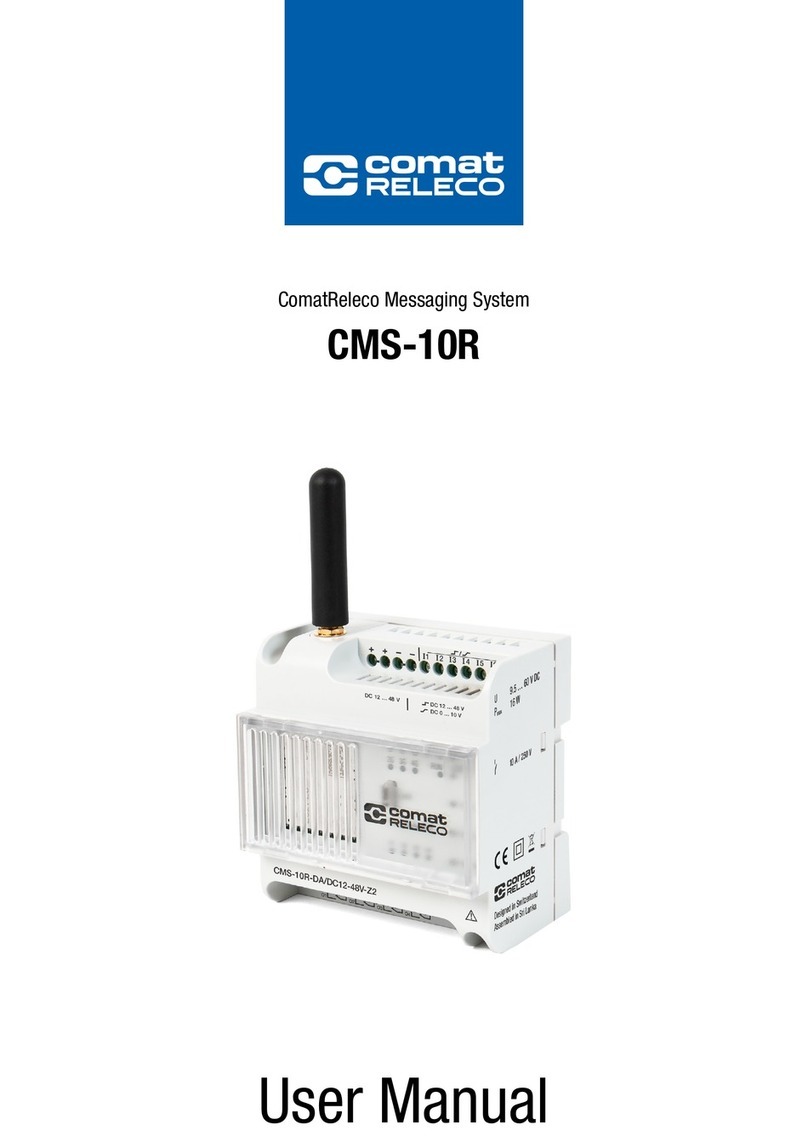
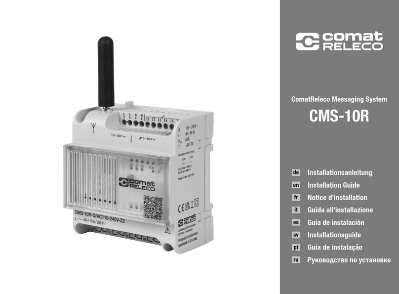
Comat Releco BoxX 2 Series User manual

User Manual
BoxX 2 series PLC is an upgraded version of BoxX series PLC.
Before you use the product, please kindly read the manual
carefully so as to ensure proper use of the product.
ComatReleco PLC + HMI
BoxX 2

ComatReleco BoxX 2 | User Manual | 68102-013-54-001 | 2
Important information
ComatReleco reserves the right to alter, correct, and/or improve the technical documentation and the products described in the technical doc-
umentation at its own discretion and without giving prior notice, insofar as this is reasonable for the user. The same applies to any technical
changes that serve the purpose of technical progress.
The receipt of technical documentation (in particular user documentation) does not constitute any further duty on the part of ComatReleco to
provide information on modifications to products and/or technical documentation. You are responsible for verifying the suitability and intended
use of the products in your specific application, in particular with regard to observing the applicable standards and regulations. All information
made available in the technical data is supplied without any accompanying guarantee, whether expressly mentioned, implied or tacitly assumed.
In general, the provisions of the current standard Terms and Conditions of ComatReleco apply exclusively, in particular as concerns any warranty
liability.
This user manual contains important information for the commissioning, operation, maintenance and disposal of the device. You will also receive
information and important tips for your safety and help with any issues. The user manual must be made physically or electronically available
with the equipment and must be included in the supply when the equipment is transferred. It is also available on the ComatReleco web portal.
Copyright
This manual, including all illustrations contained herein, is copyright protected. Any changes to the contents or the publication of extracts of
this document is prohibited.
ComatReleco reserves the right to register its own intellectual property rights for the product identifications of ComatReleco products that are
used here. Registration of such intellectual property rights by third parties is prohibited.
Other product identifications may be afforded legal protection, even where they may not be indicated as such.
Disclaimer
The owner of this device is responsible for ensuring that the instructions and notes in this manual are read, understood and followed by the
personnel concerned before putting the device into operation. Failure to observe the instructions may result in serious bodily injury and/or
damage to property. ComatReleco assumes no liability for personal injury, damage to property or financial losses.
Unauthorized modifications and changes to the device can affect safety and are not permitted. This leads to a limitation of the warranty and
may result in loss of product conformity.

ComatReleco BoxX 2 | User Manual | 68102-013-54-001 | 3
Tabel of contents
Important information.....................................................................................................................................................................2
Copyright .......................................................................................................................................................................................2
Disclaimer......................................................................................................................................................................................2
1 Introduction..................................................................................................................................................................................4
1.1 Structure of BoxX 2 ........................................................................................................................................................................4
1.2 Specifications and models..............................................................................................................................................................4
1.3 BoxX 2 Features.............................................................................................................................................................................5
2 Installation and wiring.................................................................................................................................................................6
2.1 Installation .....................................................................................................................................................................................6
2.1.1 Methods.........................................................................................................................................................................................6
2.1.2 Dimensions (unit:mm) ....................................................................................................................................................................7
2.2 Wiring of BoxX 2.............................................................................................................................................................................7
2.2.1 Connection of power supply ...........................................................................................................................................................8
2.2.2 BoxX 2 Input Connection ................................................................................................................................................................8
2.2.3 BoxX 2 output connection...............................................................................................................................................................9
3 Programming on BOXX 2 panel .................................................................................................................................................11
3.1 BoxX 2 status display interface.....................................................................................................................................................11
3.2 Password confirming....................................................................................................................................................................11
3.3 Function Interface ........................................................................................................................................................................12
3.3.1 FAB/Rom Interface .......................................................................................................................................................................12
3.3.2 Setting interface...........................................................................................................................................................................15
4 Communication connection.......................................................................................................................................................16
4.1 BoxX 2 download port ..................................................................................................................................................................16
4.2 BoxX 2 485 interface....................................................................................................................................................................16
4.2.1 BoxX 2 A1B1 interface..................................................................................................................................................................16
4.2.2 BoxX 2 A2B2 interface..................................................................................................................................................................16
5 Functional comparison ..............................................................................................................................................................18
6 Technical Parameters ................................................................................................................................................................19
6.1 General technical parameters.......................................................................................................................................................19
6.2 AF-10MR-A2/AF-20MR-A2...........................................................................................................................................................19
6.3 AF-10MT-D2/AF-20MT-D2 ...........................................................................................................................................................20
6.4 AF-10MR-D2/AF-20MR-D2 ..........................................................................................................................................................20
6.5 AF-10MT-E2/AF-20MT-E2............................................................................................................................................................21
6.6 AF-10MR-E2/AF-20MR-E2 ...........................................................................................................................................................22
6.7 AF-10MT-GD2/AF-20MT-GD2.......................................................................................................................................................22

ComatReleco BoxX 2 | User Manual | 68102-013-54-001 | 4
1 Introduction
BoxX 2 series PLC is an upgraded version of old BoxX PLC, which is programmed by the use of a Function Block Diagram. The programming of
BoxX 2 is simpler and easier to learn than that of a conventional PLC, which uses ladder diagrams and associated instructions. In the design
concept of BoxX 2 series products, it adds power indicator, comes with 2-way 485 communication interface, supports standard MODBUS RTU
protocol and can modify parameters and other functions through the LCD panel, which greatly reduces the user’s cost investment, and for
the operation It brings great convenience. The volume of BoxX 2 series products follows the old BoxX 2’s small size, light weight and other
characteristics, and is especially suitable for internal installation and use. Now BoxX 2 are being widely used in many fields such as industry,
commerce, mining, agriculture, home automation, etc.
1.1 Structure of BoxX 2
1.2 Specifications and models
Item Type Power supply Input Output
1 AF-10MR-A2 110 – 220 V AC 6 points AC digital input 4 points relay output
2 AF-10MR-E2 12 – 24 V UC 6 points AC/DC digital input 4 points relay output
3 AF-10MT-E2 12 – 24 V DC 6 points DC digital input 4 points transistor output (equivalent NPN)
4 AF-10MR-D2 12 – 24 V DC 6 points DC (with analog) digital input 4 points relay output
5 AF-10MT-D2 12 – 24 V DC 6 points DC (with analog) input 4 points transistor output (equivalent NPN)
6 AF-10MT-GD2 12 – 24 V DC 6 points DC (with analog) input 4 points transistor output (equivalent PNP)
7 AF-20MR-A2 110 – 220 V AC 12 points AC digital input 8 points relay output
8 AF-20MR-E2 12 – 24 V UC 12 points AC/DC digital input 8 points relay output
9 AF-20MT-E2 12 – 24 V DC 12 points DC digital input 8 points transistor output (equivalent NPN)
10 AF-20MR-D2 12 – 24 V DC 12 points DC (with analog) digital input 8 points relay output
11 AF-20MT-D2 12 – 24 V DC 12 points DC (with analog) input 8 points transistor output (equivalent NPN)
12 AF-20MT-GD2 12 – 24 V DC 12 points DC (with analog) input 8 points transistor output (equivalent PNP)
13 AF-HMI The removable LCD panel that can modify parameters through the panel
14 AF-C232-2 232 interface communication lines for downloading programs
15 AF-DUSB2 USB interface communication lines for downloading programs
16 RTD module Detect the temperature signal directly
Figure 1
1Power terminals
2Input terminals
3Output terminals (Relay or transistor)
4Program download port
5Operating keys
6Two channel of 485 communication interface (A1/B1 + A2/B2)
7LCD display panel
8Power Indicator (Red Indicator, Flashing frequency 1 Hz)

ComatReleco BoxX 2 | User Manual | 68102-013-54-001 | 5
1.3 BoxX 2 Features
1. Removable LCD display (AF-HMI)
AF-HMI (Removable LCD display) can be used flexibly according to your needs. When you need it, you can install and use the keys on the panel
to query/set the BoxX 2 address, BoxX 2 system time, modify the function block parameters and manually calibrate the analog quantity, etc.
When you don’t need it, you can disassemble it and replace it with an ordinary panel, which will greatly reduce your cost of use. However,
compared with AF-LCD, the AF-HMI operator panel cannot be programmed manually.
2. FB programming and big program storage capacity
BoxX 2 uses a function block to realize the control function that the previous PLC needed a large section of the program to realize, and several
functional blocks are connected in a certain way to complete more complicated control functions. The BoxX 2 can accommodate up to 127
function block programs. There are enough resources for you to implement complicated control requirements. Once the program is written, it
will never be lost. BoxX 2 uses a larger memory capacity chip than BoxX.
3. Exquisite and compact design
If you are looking to make your device delicate, BoxX 2 will be your best partner.
AF-10 Series: 71.6 mm x 90.4 x 57.6 mm
AF-20 Series: 126.4 mm x 90.4 x 57.6 mm
4. Free programming software
The free QUICK II programming software is an extremely friendly human-machine programming interface. It not only can edit function charts,
but also can provide functions such as off-line simulation of your programs and on-line monitoring of I/O status. It solves many inconveniences
such as customer online testing.
5. Real-time clock function
The BoxX 2 has a clock-recording function that can run at any time you need, and you can set up to 127 different time periods, especially for
systems that require time control. The timing is accurate to the second, and BoxX 2’s RTC precision error is greatly improved to 20 s/month
compared with BoxX, making your time control more accurate.
6. Analog inputs
BoxX 2 can receive analog input except for switch input so as to complete the control of temperature, humidity, pressure, flow, liquid level, etc.,
and can monitor the analog value status of the PC through short distance or long distance. And BoxX 2 simulation accuracy and BoxX greatly
improved to 10 (0.1 V).
7. Security password lock function
BoxX 2 has absolute confidentiality for the program you write. You can set your own password before burning the program. You can modify the
application only after entering the correct password. When the AF-HMI panel enters the function interface, it must enter the correct password
and protect it with the * symbol.
8. Power indicator
BoxX 2 adds red power indicator to facilitate the customer to visually check whether the machine is properly connected to the power supply.
When customers use BoxX before, it is necessary to use a multimeter to test the voltage across the power supply to determine whether the
power supply is properly connected to the customer, causing inconvenience to the customer.
9. Communication interface
In addition to downloading the communication port, BoxX 2 also adds two 485 ports to save the cost and space for customers directly. BoxX 2’s
A1B1 interface supports the standard MODBUS RTU protocol and can communicate with other manufacturers’ branded touch screens and other
devices. BoxX 2’s A2B2 interface is used to communicate with our SH300 text display. A detailed description of the communication interface
is given chapter 4.
10. Communication protocol
In addition to the custom protocol for the download port, BoxX 2 adds the standard MODBUS RTU protocol. The old BoxX only supports custom
protocols.

ComatReleco BoxX 2 | User Manual | 68102-013-54-001 | 6
2 Installation and wiring
2.1 Installation
2.1.1 Methods
BoxX 2 is small so it is suitable to be fit inside panels or machinery. The installation of BoxX 2 is extremely easy.
1. Use standard 35 mm DIN rail mounting BoxX 2
2. Use screw mounting holes on BoxX 2 for direct mounting
Figure 2.1 Use stand and DIN rail for installation of BoxX 2
Screw mounting hole
Buckle at the bottom
35 mm DIN rail
Screw mounting hole
Do not remove the AF-HMI while it is powered on. Otherwise it may cause mechanical damage and even
endanger the safety of the operator. We recommend powering off and plugging the AF-HMI panel.

ComatReleco BoxX 2 | User Manual | 68102-013-54-001 | 7
2.1.2 Dimensions
2.2 Wiring of BoxX 2
Screwdriver with a spade tip width of 3 mm is needed for the wiring of BoxX 2 series. As for the cross section of a wire. The following two sizes
are at choice:
- 1 × 2.5 mm2
- 2 × 1.5 mm2
Figure 2.2 AF-10 Series (mm)
Figure 2.3 AF-20 Series (mm)

ComatReleco BoxX 2 | User Manual | 68102-013-54-001 | 8
2.2.1 Connection of power supply
1. For BoxX 2s like AF-10MR-A2 and AF-20MR-A2, its applicable power supply is 100 ~ 240 V AC, 50/60 Hz.
The grid voltage fluctuation range is about 10 %.
2. For BoxX 2s like AF-10MR-D2, AF-20MR-D2, AF-10MT-D2, AF-20MT-D2, AF-10MT-GD2,
AF-20MT-GD2, AF-10MT-E2, AF-20MT-E2, Its applicable power supply voltage is 12 – 24 V DC.
3. For BoxX 2s like AF-10MR-E2 and AF-20MR-E2, its applicable power supply voltage is 12 – 24 V UC.
BoxX 2 series power wiring diagram is as shown in Figure 2.4 and Figure 2.5,
2.2.2 BoxX 2 Input Connection
BoxX 2 input can be either digital switch, such as on/off switches and photoelectric baffle and sunshine switch etc., or analog, such as pressure,
temperature, humidity, flow and so on. The specific requirements are as follows:
Demand AF-10MR-A2
AF-20MR-A2
AF-10/20MR-D2
AF-10/20MT-D2
AF-10/20MT-GD2
AF-10MR-E2
AF-20MR-E2
AF-10MT-E2
AF-20MT-E2
switch status 0 < 40 V AC < 3.5 V DC < 4.5 V UC < 3.5 V DC
Input current < 0.1 mA < 0.4 mA < 0.2 mA < 0.5 mA
switch status 1 85 – 240 V AC 10 – 24 V DC 10 – 24 V UC 10 – 24 V DC
Input current < 0.2 mA < 2.5 mA < 2 mA < 2.5 mA
Proximity switch type with direct input 2-wire system/3-wire system/4-wire
Note:
1. Analog can be input into analog-receivable BoxX 2s like AF-10/20MR-D2, AF-10/20MT-D2, AF-10/20MT-GD2 through all the
input ports (I1-I6/I1-IC). As long as the analog-related function blocks are used in the program, Its port is automatically set to analog
input. If in the program do not use the analog-related function blocks, its port is automatically set to digit input.
2. The analog inputs require 0 ~ 10 V DC voltage signals, which are divided equally in 0.1 V increments. When you edit the program,
all the block parameters related to the analog inputs are based on the minimum increment of 0.1 V.
3. When the input voltage is higher than 10.0 V DC, it can only be used as switch, not be used as analog.
4. For digit input,when the switch state changes from 0 to 1, the time of the 1 state must be greater than 50 ms.
When the switch state changes from 1 to 0, the 0 state must also exist for more than 50 ms.
Figure 2.4 AC Type Figure 2.5 DC Type

ComatReleco BoxX 2 | User Manual | 68102-013-54-001 | 9
BoxX 2 input connection:
2.2.3 BoxX 2 output connection
AF-10MR-A2/AF-20MR-A2/AF-10MR-E2/AF-20MR-E2/AF-10MR-D2/AF-20MR-D2 type BoxX 2 is the relay output, the relay’s contact to the
power and input is isolated. AF-10MT-D2/AF-20MT-D2/AF-10MT-GD2/AF-20MT-GD2/AF-10MT-E2/AF-20 MT-E2 type BoxX 2 is the transistor
output.
1. Requirements for the relay outputs
Various loads can be connected to the output of BoxX 2, such as: incandescent lamps, fluorescent lamps, motors, contactors, etc.The maximum
output current that BoxX 2 can provide is: non-inductive load 10 A, inductive load 2 A.
The connection is shown as shown in Figure 2.9:
Figure 2.6 AC Type Figure 2.7 DC Type
Figure 2.8 DC Type (D/GD)
Figure 2.9 Relay output

ComatReleco BoxX 2 | User Manual | 68102-013-54-001 | 10
2. Requirements for the transistors outputs
The transistor is divided into D type and GD type.
The load connected to BoxX 2 must have the following characteristics:
When the switch is ON (Q=1), the maximum current is 2 A.
1) Type D connection is shown in Figure 2.10:
2) Type GD connection is shown in Figure 2.11:
Figure 2.10 Transistor Output (D type)
Figure 2.11 Transistor Output (GD type)

ComatReleco BoxX 2 | User Manual | 68102-013-54-001 | 11
3 Programming on BoxX 2 panel
BoxX 2 operation panel is a simple man-machine interface, which is completed by the following eight buttons to complete the panel operation.
3.1 BoxX 2 status display interface
After the BoxX 2 is powered on, the AF-HMI enters the BoxX 2 status display interface.
Take 10 points as an example, as shown in Figure 3.2,
The I listed above is input: the status of 6 input ports
The following Q is output: status of 4 output ports
(*indicate ON, i.e. status «1», indicates OFF, i.e. status «0»)
The time is displayed under the current day of the week.
3.2 Password confirming
When you observe the AF-HMI in the above status display interface, press the
ESC
and
OK
keys at the same time to enter the password confir-
mation screen, as shown in Figure 3.3, BoxX 2 needs to enter the password value at this time, and the cursor stays at the high position of the
password. You can use the
+
and
–
keys to change the numeric value (0 - 9).
When you press the
+
and
–
key for the first time, the password value is 0. You can use the and keys to move the password input
position and enter the remaining number of password values. If the user password is entered correctly, it will enter the panel function interface;
If the user password is not entered correctly, it will stay on the input password interface.
Four-digit password, every time you enter a digit to enter the next digit, the previous digit is hidden with the *symbol, and you must enter the
four-digit number to enter the BoxX 2 function interface.
Figure 3.1 Operating buttons
Figure 3.2 Status display
Figure 3.3 Password Interface

ComatReleco BoxX 2 | User Manual | 68102-013-54-001 | 12
3.3 Function Interface
When you enter the following function interface, please kindly use and keys and to move the left >key and press
OK
key to select the
function, including four options.
Editor.. Program Edit (System Reserved, BoxX 2 not enabled)
FAB/Rom Read BoxX 2 program, simulate calibration, modify BoxX 2 address, etc.
Set.. Real time clock setting and password setting
Run Run BoxX 2 program, click RUN to return to BoxX 2 status display interface
3.3.1 FAB/Rom Interface
When the user enters into the FAB/Rom interface as shown above, then when the user enters the Calibrate interface, Rom→FAB interface and
FAB_Addr interface under the BoxX 2 function interface, the BoxX 2 machine will stop running.
Calibrate Analog calibration
Rom→FAB Read BoxX 2 program
FAB_Addr View or set the BoxX 2 address (default address 000)
MODEM System Reserved (BoxX 2 is not enabled for this feature)
3.3.1.1 Analog Calibration Interface
The analog channel calibration method is as follows:
1. When you enter the Calibrate interface as above, please kindly press and hold the
OK
and keys on the LCD panel to enter the calibration
page. Separate each analog channel by analog (AI: 01 corresponds to I1), and input the channel number to be calibrated, and press
OK
to
confirm.
Figure 3.4 Function Interface
Figure 3.5 FAB/Rom Interface
Figure 3.6 Analog Calibration Interface

ComatReleco BoxX 2 | User Manual | 68102-013-54-001 | 13
2. When the minimum value is prompted, an external power supply is required to input the minimum voltage value for this channel, then press
OK
to confirm and mark as Vmin. When the maximum value is prompted,an external power supply is required to input the maximum voltage
value for this channel. Then Press
OK
to confirm it and mark as Vmax. After calibrate successful, the screen will prompt succeed.
The V min and V max inputs must be between 0 V and 10 V. (The maximum calibration value of the value must be greater than the minimum
calibration value)
3. After successful analog calibration, BoxX 2 needs to be powered on again.
4. Other channel calibrations is similar as above. After the analog calibrate successful, when using an analog-related module, the value of the
analog input pin input (0 V – 10 V) is not the actual input voltage value, but follows the mathematical calculation formula (V input – V min)/
(V max – V min) * 10.
3.3.1.2 Rom→FAB Program Interface
You can view the function block number of the BoxX 2 program on this interface, and can modify the parameters of the function block number.
Such as DPR (Delay Putting Relay), DDR (Delay Disconnection Relay) and UCN (Up Counter) and so on.
When you enter the Rom→FAB program interface through FAB/Rom interface, select the function block number to be viewed or modified by
the
+
and
–
keys. The function block number in the AF-HMI panel starts from 0, and the B0 block number corresponds to the B1 block
number in the QUICK II software.
1. Timing function block Time unit:
Unit Unit (1-hour, 2-minute, 4-second)
Int. Integer bit
MDecimal places
As shown in Figure 3.8, B002 function block is MPLR single pulse function block, The parameter is 30.3 seconds. If you want to modify the
parameter, pls kindly remove the cursor to the modified bit you need, then set up the parameter via
+
and
–
keys.
2. Counting function clock
Counting unit:
Consisting of six digits, the highest position is the leftmost, the lowest position is the rightmost, and his range is 1 - 999999
For example, as shown in Figure 3.9:
B018 function block is COUNTU, the parameter of Upward counting function block is 100. If you want to modify the parameter, pls kindly remove
the cursor to the modified bit you need, then set up the parameter via
+
and
–
keys.
Figure 3.7 Analog Calibration Interface
Figure 3.8 Timing function block
Figure 3.9 Counting function clock

ComatReleco BoxX 2 | User Manual | 68102-013-54-001 | 14
3. Clock switching function
The parameter setting of the clock switch function block is divided into date type and week type.
For example week type, as shown in Figure 3.10:
B000 function block for SCHD clock switch week type, open Monday to Saturday 0:30 to 8:30. If you want to modify the parameter, you could
remove the cursor to the modified bit you need, then set up the parameter via
+
and
–
key.
For example date type, as shown in Figure 3.11:
B008 function block is SCHD clock switch date type, July 2nd, 2017 Closed at 21:00. If you want to modify the parameter, you could remove
the cursor to the modified bit you need, then set up the parameter via
+
and
–
key.
3.3.1.3 FAB_Addr Address Interface
You can view the address of BoxX 2 machine in Figure 3.12, and can modify his address.
When the user enters the FAB_Address interface through the FAB/Rom interface, the BoxX 2 address can be viewed or modified through the
+
and
–
keys.
Figure 3.10 Week type
Figure 3.11 Date type
Figure 3.12 FAB_Addr Address Interface

ComatReleco BoxX 2 | User Manual | 68102-013-54-001 | 15
3.3.2 Setting Interface
When you enter the Set.. setting interface on the BoxX 2 function interface, as shown in Figure 3.13:
When you enter the Set.. setting interface under the BoxX 2 function interface, the BoxX 2 system time and BoxX 2 password can be viewed
or modified.
Real clock time: 24 HR
Date: Y/M/D
Week: 0 for Sunday and 1-6 for Monday to Saturday
Password: BoxX 2 machine password (See chapter 3.2)
Figure 3.13 Setting Interface

ComatReleco BoxX 2 | User Manual | 68102-013-54-001 | 16
4 Communication connection
BoxX 2 series PLC not only has a download port custom protocol, but also supports Modbus RTU protocol, and can communicate with other
devices that support modbus RTU protocol.
The upper right side of the BoxX 2 is the program download port, as shown Figure 4.1. The upper left side of BoxX 2 front view is 485 interface
(A1/B1 + A2/B2), as shown in Figure 4.1:
4.1 BoxX 2 download port
The user could communicate with BoxX 2 PLC and QUICK II directly through AF-C232-2 and AF-DUSB2 so as to realize read and write programs,
read and write BoxX 2 address and online monitoring functions.
4.2 BoxX 2 485 interface
BoxX 2 supports 2-way 485 interface, One way is A1/B1 standard MODBUS RTU protocol, another way is A2/B2 and SH300 communication.
4.2.1 BoxX 2 A1/B1 interface
A1/B1 supports MODBYS RTU protocol. The address of MODBUS RTU is as below,
Address Type Read-write Property Function Code Comment
0X Only Read 01 Read the status of system (00-FF)
0X Only Read 01 Read status of digit input (100-1FF)
4X Only Read 03 Read status of AI (300-3FF)
0X Only Read 01 Read status of Output Q (200-2FF)
1: BoxX 2 is act as Modbus slave device, which responds according to the requested data by Modbus master device.
2: Communication parameters: 19200 bps, 8 data bits, 1 stop bit and no parity.
4.2.2 BoxX 2 A2/B2 interface
The A2/B2 interface is used for communication between our SH300 text display. His related parameters are as follows:
Item content
SH300 Communication port 9-pin communication port
PLC Communication port 485 interface (A2/B2)
Communication parameters 9600 bps, 8 bit, 1 stop, none
Bureau number The range of Bureau number 0-254
communication mode 485
Figure 4.1 Communication connection
Program
download port
485
Interface

ComatReleco BoxX 2 | User Manual | 68102-013-54-001 | 17
Using Address Type Description in SH300 Software
Component type Address type Address range Read/Write Description
Indicator
lamp
I 1 - 12 Read Reading input status
Q 1 - 8 Read Reading output status
M
Corresponding
intermediate relay
number in BoxX 2
program (0 - 127)
Read
Reading function block
output status in BoxX 2
program
Function
keys Q 1 - 8 Write
Write empty output port
status (unoccupied output
port in BoxX 2 program)
Dynamic
text
I 1 - 12 Read Reading input analog
value (DC PLC)
BCorresponding
block number in Read Reading parameter values
of function blocks in BoxX 2
BOXX 2 program
(1 - 128)
programs
Register
I 1 - 12 Read Reading input analog value
B
Corresponding
block number in
the BoxX 2 program
(1 - 128)
Read
Reading parameter values
of function blocks in BoxX 2
programs
Write
Write parameter values of
function blocks in BoxX 2
programs
Stick/Trend
Chart
I 1 - 12 Read Reading input analog values
B
Corresponding
block number in
the BoxX 2 program
Read
Reading parameter values
of function blocks in BoxX 2
programs

ComatReleco BoxX 2 | User Manual | 68102-013-54-001 | 18
5 Functional comparison
The BoxX 2 series PLC is an upgraded version of the BoxX series PLC. The function comparison diagrams of the two are as follows:
Item BoxX BoxX 2
Basic features
25 ˚C RTC buffer 100 h 160 h
RTC accuracy 150 s/month 20 s/month
Password Protection Yes Yes (*protection)
Expanded module Yes (voice module) None (without voice module)
Panel parameters queried/modified queried/modified
Panel programming Yes None
The function of Automatic Startup None Yes (0.5 second after Power on or download the program)
Quick II Download free of charge https://www.comatreleco.com/en/service-and-support/down-
loads-de/softwaretools-und-treiber/
Integration Communication
RS485 None Two Groups (One group SH300 + one modbus only read)
Communication Rate 9600 9600/19200
Communication Protocol Self-defined protocol Self-defined/Standard Modbus (Note 1)
AI Characteristics
AD Resolution 8 bits (0.2 V) 10 bits (0.1 V)
Signal Type 0 – 10 V DC 0 – 10 V DC

ComatReleco BoxX 2 | User Manual | 68102-013-54-001 | 19
6 Technical Parameters
6.1 General technical parameters
Item Basis Condition
Climate environment
Humidity Cold: EC68-2-1
Heat: IEC68-2-2
Horizontal installation
Vertical installation
-20 ˚ – 70 ˚C
-20 ˚ – 70 ˚C
Storage/Transportation -40 ˚ – 70 ˚C
Relative humidity IEC68-2-30 5 - 95 % without condensation
Atmospheric pressure 795 – 1080 kpa
Pollutants IEC68-2-42
IEC68-2-43
SO2 10 cm3/m3, 4 days
H2S 1 cm3/m3, 4 days
Mechanical environment
Protection type IP20
Vibration 2 IEC68-2-6 10 – 57 Hz (constant amplitude 0.15 mm)
57 – 150 Hz (constant Acceleration 2 g)
Impact IEC68-2-27 18 impacts (semi sine 15 g / 11 ms)
Fall IEC68-2-31 Falling height 50 mm
Freely falling objects (with package) IEC68-2-32 1 m
Electromagnetic compatibility (EMC)
Static discharge Severe grade 3 8 kV air discharge, 6 kV contact discharge
Electromagnetic field IEC801-3 Field strength 10 V/m
Interference suppression EN55011 Limitation grade B group 1
Shock pulse IEC801-4
Severe grade 3
2 kV for power line
2 kV for power line
IEC/VDE safety information
Insulation Intensity IEC1131 Meet the requirements
25 ˚C clock buffer memory Typical 100 h
RTC accuracy ± Max 20 s/Month
6.2 AF-10MR-A2/AF-20MR-A2
Power Supply
The rated voltage of power supply 100 – 240 V AC
Allowable range of the rated input voltages
VDE0631:
IEC1131:
Allowable main frequency:
85 – 260 V AC
85 – 260 V AC
47 ~ 63 Hz
Power consumption (220 V AC) AF-10MR-A (6 W)
AF-20MR-A (10 W)
Digital input
Input voltage L1
Signal 0:
Signal 1:
0 – 40 V AC
80 – 240 V AC
Input Current of signal 1 Typical 0.2 mA (230 V AC)
Delay Time
Changed From 1 to 0:
Changed From 0 to 1:
Typical 50 ms
Typical 50 ms
Length of Power Line (without shield) 100 m
Digital output

ComatReleco BoxX 2 | User Manual | 68102-013-54-001 | 20
Output Type Relay Output
Electrical Isolation Yes
Group 1
Continuous Current Ith Max 10 A
Incandescent Lamp Load
(25,000 switch cycles)
1000 W (230 / 240 V AC)
500 W (115 / 120 V AC)
Fluorescent Light Tube with Electrical Controller
(25,000 Switch cycles) 10 × 58 W (230 / 240 V AC)
Fluorescent Light Tube with Regular Compensation
(25,000 Switch cycles) 1 × 58 W (230 / 240 V AC)
Fluorescent Light Tube without Compensation
(25,000 Switch cycles) 10 × 58 W (230 / 240 V AC)
Short Circuit Protection cos1 Power Supply Protection B16 600 A
Output Relay Protection Max. 20 A
Feature B16
Switch Frequency
Machine 10 Hz
Resistor Load/Lamp Load 2 Hz
Induced Load 0.5 Hz
6.3 AF-10MT-D2/AF-20MT-D2
Power Supply
The rated voltage of power supply 12 / 24 V DC
Allowable range of the rated input voltage
Power Consumption (24 V DC)
(Output full load)
10 – 28 V DC
Typical 80 mA
Typical 2 W
Input section (digital input)
Signal 0
Signal 1
< 3.5 V DC
10 – 24 V DC
Input current of signal 1 < 2.5 mA
Input section (analog input)
Signal 1 0 – 10 V DC
Input current of signal 1 < 0.8 mA
Delay Time
Changed From 1 to 0:
Changed From 0 to 1:
Typical 50 ms
Typical 50 ms
Length of Power Line (without shield) 100 m
Digital output
Output type
Output voltage
Output Current
Transistor output (equivalent NPN)
≤ 80 V DC
Max 2 A
Short Circuit and Overload Protection No
Current limit of short circuit about 2 A
Reduction of the rated value No (even in the whole temperature range)
6.4 AF-10MR-D2/AF-20MR-D2
Power Supply
The rated Voltage of power supply 12 / 24 V DC
Allowable range of the rated input voltage 10 – 28 V DC
Power Consumption (24 V DC)
(Output full load)
AF-10MR-D2 (4 W)
AF-20MR-D2 (5 W)
Input section (digital input)
This manual suits for next models
15
Table of contents
Other Comat Releco Conference System manuals