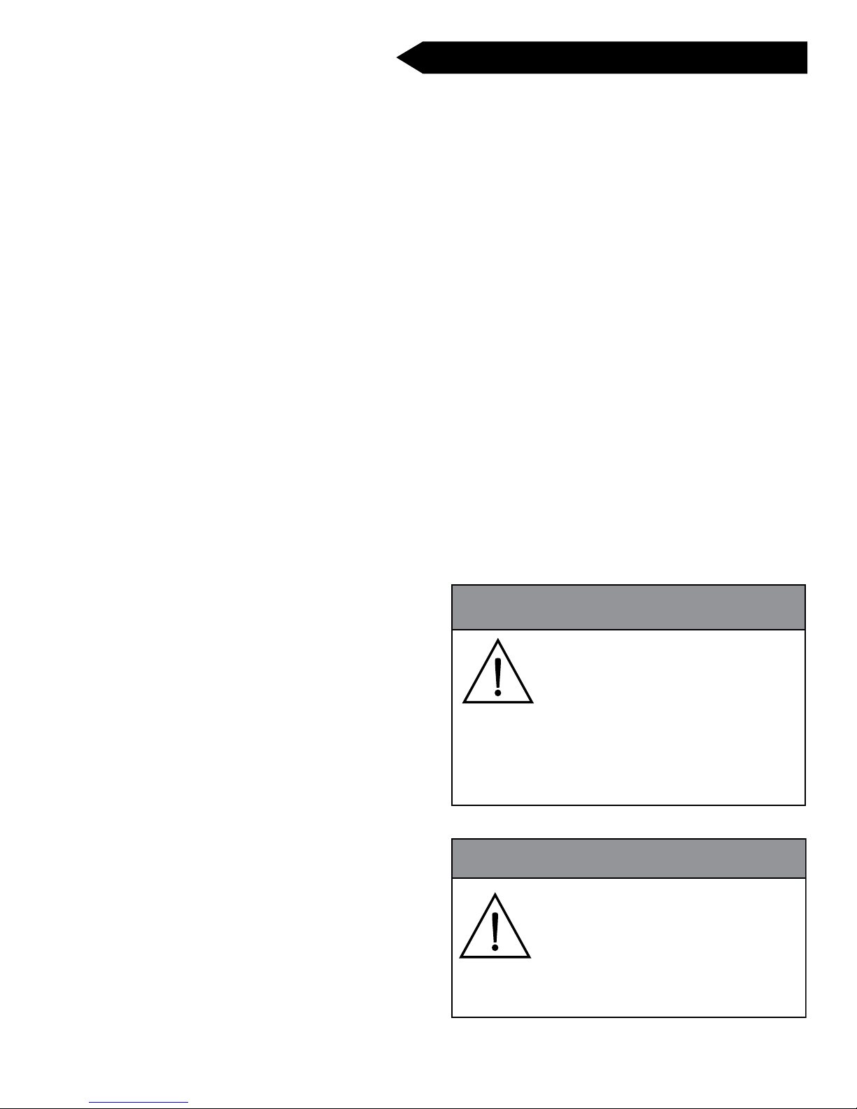
COMBITHERM CT PROformance Series User manual

MN-35947 • REV. 8 • 08/15
CTP6-10E, CTP6-10G
CTP10-10E, CTP10-10G
CTP7-20E, CTP7-20G
CTP10-20E, CTP10-20G
CTP20-10E, CTP20-10G
CTP20-20E, CTP20-20G
InstallatIon
CTC6-10E, CTC6-10G
CTC10-10E, CTC10-10G
CTC7-20E, CTC7-20G
CTC10-20E, CTC10-20G
CTC20-10E, CTC20-10G
CTC20-20E, CTC20-20G
WARNING
Improper installation, alteration,
adjustment, service, cleaning, or
maintenance could result in property
damage, severe injury, or death.
READ and UNDERSTAND the
installation, operating and
maintenance instructions thoroughly
before installing, servicing, or
operating this equipment.
WARNING
FOR YOUR SAFETY
DO NOT store or use gasoline or
other flammable vapors or liquids in
the vicinity of this or any other
appliance.
W164 N9221 Water Street • P.O. Box 450
Menomonee Falls, Wisconsin 53052-0450 U.S.A.
PHONE: 262.251.3800 • 800.558.8744 U.S.A. / CANADA
FAX: 262.251.7067 • 800.329.8744 U.S.A. ONLY
www.alto-shaam.com Consult instructions
for operation and use.

DANGER
Before starting the appliance, make
certain you do not detect the odor
of gas.
IF YOU SMELL GAS:
• Shut off the gas supply immediately.
• Do not attempt to light any appliance.
• Do not touch any electrical elements.
• Extinguish any open fl ame.
• Evacuate the area.
• Use a telephone outside the property
and immediately contact your gas
supplier.
• If unable to contact your gas supplier,
contact the fire department.
i
Delivery.......................................................................... 1
Unpacking ..................................................................... 1
Safety Procedures and Precautions.............................. 2
Installation
Installation Codes and Standards............................. 4
Ventilation Requirements ........................................... 4
Sound Pressure.......................................................... 4
Free Mechanical Start-Up.......................................... 4
Installation Duties and Responsibilities...................... 5
Pre-Installation Checklist ........................................... 7
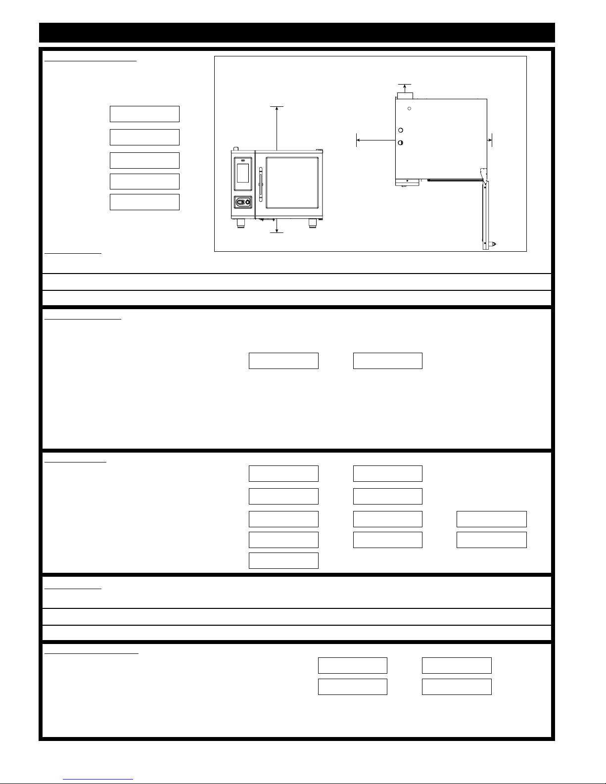
Specications, CTP6-10E........................................ 10
Specications, CTC6-10E........................................ 11
Specications, CTP6-10G........................................ 12
Specications, CTC6-10G....................................... 13
Specications, CTP10-10E...................................... 14
Specications, CTC10-10E...................................... 15
Specications, CTP10-10G...................................... 16
Specications, CTC10-10G..................................... 17
Specications, CTP7-20E........................................ 18
Specications, CTC7-20E........................................ 19
Specications, CTP7-20G........................................ 20
Specications, CTC7-20G....................................... 21
Specications, CTP10-20E...................................... 22
Specications, CTC10-20E...................................... 23
Specications, CTP10-20G...................................... 24
Specications, CTC10-20G..................................... 25
Specications, CTP20-10E...................................... 26
Specications, CTC20-10E...................................... 27
Specications, CTP20-10G...................................... 28
Specications, CTC20-10G..................................... 29
Specications, CTP20-20E...................................... 30
Specications, CTC20-20E...................................... 31
Specications, CTP20-20G...................................... 32
Specications, CTC20-20G..................................... 33
Lifting Instructions.................................................... 34
Clearance Requirements.......................................... 35
Positioning on Site, Countertop Models ................. 35
Stand Installation .................................................... 35
Positioning on Site, 20-10, 20-20 Models............... 36
Options and Accessories ........................................ 37
Electrical Safety Regulations ................................... 38
Electrical Connection for Gas Models ..................... 39
Electrical Connection for Electric Models ................ 40
Ventilation Requirements ......................................... 42
Gas Supply & Installation ......................................... 43
Gas Leak Testing...................................................... 47
Gas Exhaust............................................................. 47
Water Quality Requirements .................................... 48
Water Supply & Installation ...................................... 49
Water Drainage......................................................... 50
Mobile Equipment Restraint..................................... 52
Combihood PLUS™ Installation .............................. 53
Grease Collection Hook-up...................................... 55
Liquid Cleaning Hook-up ......................................... 56
CT PROformance Start-up Procedures ................... 57
CT PROformance Screen Calibration ...................... 57
CT Classic Start-up Procedures .............................. 59
Post-Installation Checklist ...................................... 60
Preventative Maintenance Checklist........................ 62
Error Codes ............................................................. 68
Service Parts ............................................................ 76
Warranty
Original Equipment Limited Warranty ...................... 77
Transportation Damage and Claims........................ 78
InstallatIon
table of contents
Please post the following instructions in a prominent
location in the event the user smells gas.

COMBITHERM CT PROFORMANCE AND CT CLASSIC SERIES • INSTALLATION MANUAL • MN-35947 • 1.
DELIVERY
This Alto-Shaam appliance has been thoroughly
tested and inspected to ensure only the highest
quality unit is provided. Upon receipt, check for any
possible shipping damage and report it at once to the
delivering carrier. See Transportation Damage and
Claims section located in this manual.
This appliance, complete with unattached items
and accessories, may be delivered in one or more
packages. Ensure all standard items and options
have been received with each model as ordered.
Save all the information packed with the appliance.
Register online at www.alto-shaam.com to ensure
prompt service in the event of a warranty parts and
labor claim.
This manual must be read and understood by all
people using or installing the equipment model.
Contact the Alto-Shaam Tech Team Service
Department if you have any questions concerning
installation, operation, or maintenance.
1-800-558-8744; [email protected]
UNPACKING
• Carefully remove the appliance
from the carton or crate.
NOTICE: Do not discard the
carton and other
packaging material
until you have
inspected the unit
for hidden damage
and tested it for
proper operation.
• Read all instructions in this manual carefully
before installing this appliance, using the appliance
or performing routine maintenance. Following
procedures other than those indicated in this
guide to use and clean the appliance is considered
inappropriate and may cause damage, injury or
fatal accidents, in addition to invalidating the
guarantee and relieving Alto-Shaam of all liability.
• DO NOT DISCARD THIS MANUAL.
This manual is considered part of the appliance
and is provided for the owner or manager of the
business and for training personnel. Additional
manuals are available from the Alto-Shaam
Tech Team Service Department.
• Remove all protective plastic film, packaging
materials, and accessories from the appliance
before connecting electrical power. Store any
accessories in a convenient place for future use.
®
®
WARNING
Appliance and accessories may be
heavy. To prevent serious injury,
ALWAYS use a sufficient number
of trained and experienced workers
when moving or leveling appliance
and handling accessories.
ENVIRONMENTAL CONDITIONS
• Operational Environmental Conditions
• Unit must acclimate to room temperature in the
environment it is placed. 24 hours is recommended.
• Ambient temperature range of 50° to 110°F (10° to 43°C).
• Relative humidity of less than 95% non-condensation.
• Atmospheric pressure range of 50KPa to 106KPa.
Always include both model and serial numbers in your correspondence
regarding the unit.
Model: _____________________________________
Serial Number: _____________________________________
Purchased From: _____________________________________
Date Installed: ____________ Voltage: _______________
SERIAL NUMBER IS REQUIRED FOR ALL INQUIRIES

COMBITHERM CT PROFORMANCE AND CT CLASSIC SERIES • INSTALLATION MANUAL • MN-35947 • 2.
CAUTION
Used to indicate the presence of a hazard that
can or will cause minor personal injury, property
damage, or a potential unsafe practice if the
warning included with this symbol is ignored.
CAUTION
Used to indicate the presence of a
hazard that can or will cause minor or
moderate personal injury or property
damage if the warning included with
this symbol is ignored.
DANGER
Used to indicate the presence of
a hazard that WILL cause severe
personal injury, death, or substantial
property damage if the warning
included with this symbol is ignored.
WARNING
Used to indicate the presence of
a hazard that CAN cause personal
injury, possible death, or major
property damage if the warning
included with this symbol is ignored.
• This appliance is intended to cook, hold or process
foods for the purpose of human consumption. No
other use for this appliance is authorized and is
therefore considered dangerous. The appliance
must not be used to cook food containing flammable
materials (such as food with alcohol). Substances
with a low flash point can ignite spontaneously and
cause a fire.
• This appliance is intended for use in commercial
establishments where all operators are familiar with
the purpose, limitations, and associated hazards of
this appliance. Operating instructions and warnings
must be read and understood by all operators and
users. We recommend regular training of your
staff to avoid the risk of accident or damage to the
unit. Operators must also receive regular safety
instructions.
• Any trouble shooting guides, component views, and
parts lists included in this manual are for general
reference only and are intended for use by qualified
and trained technicians.
• This manual should be considered a permanent
part of this appliance. This manual and all supplied
instructions, diagrams, schematics, parts lists,
notices, and labels must remain with the appliance
if the item is sold or moved to another location.
NOTICE: Used to notify personnel of
installation, operation, or
maintenance information that is
important but not hazard related.
SAFETY PROCEDURES
AND PRECAUTIONS
Knowledge of proper procedures is essential to the
safe operation of electrically and/or gas energized
equipment. The following hazard signal words and
symbols may be used throughout this manual.
Used to indicate that referral to
operating instructions is a mandatory
action. If not followed the operator
could suffer personal injury.
Used to indicate that referral to
operating instructions is recommended
to understand operation of equipment.
NOTICE: For equipment delivered for use in
any location regulated by the
following directive:
DO NOT dispose of electrical or
electronic equipment with other
municipal waste.

COMBITHERM CT PROFORMANCE AND CT CLASSIC SERIES • INSTALLATION MANUAL • MN-35947 • 3.
• To prevent serious injury, death or property
damage, your appliance should be inspected and
serviced at least every twelve (12) months by an
authorized service partner or trained technician.
• ONLY allow an authorized service partner or
trained technician to service or to repair your
appliance. Installation or repairs that are not
performed by an authorized service partner or
trained technician, or the use of non-factory
authorized parts will void the warranty and relieve
Alto-Shaam of all liability.
• When working on this appliance, observe
precautions in the literature, on tags, on labels
attached to or shipped with the appliance and other
safety precautions that may apply.
• If the appliance is installed on casters freedom of
movement of the appliance must be restricted so
that utility connections (including gas, water, and
electricity) cannot be damaged when the unit is
moved. If the appliance is moved, make sure that all
utility connections are properly disconnected. If the
unit is returned to its original position, make sure
that any retention devices and utility connections
are properly connected.
• ONLY use the appliance when it is stationary.
Mobile oven racks, mobile plate racks, transport
trolleys, and appliances on casters can tip over
when being moved over an uneven floor or
threshold and cause serious injury.
• ALWAYS apply caster brakes on mobile appliances
or accessories when these are not being moved.
These items could move or roll on uneven floors
and cause property damage or seious injury.
• Be extremely careful when moving appliances
because the food trays may contain hot fluids that
may spill, causing serious injury.
• ALWAYS open the appliance door very slowly.
Escaping hot vapors or steam can cause serious
injury or death.
ADDITIONAL SAFETY PROCEDURES
AND PRECAUTIONS
• If your gas appliance is installed under an
exhaust hood, the hood must be switched ON
when the oven is in use to avoid the build up of
combustion gases. Failure to do so may result in
serious injury, death or property damage.
•
NEVER place objects near the oven exhaust vents.
This area is hot and could be a potential ignition
source for a fire.
• Do not allow objects to block or obstruct the area
below the oven base. This may result in fire,
damage to the equipment or serious injury.
• Do not use the attached hand-held hose to spray
anything other than the interior of the oven
compartment.
• Do not use the attached hand-held hose on the
surface of a hot cooking compartment. The
sudden temperature change can damage the oven
interior. Allow the oven to cool to a minimum of
150°F (66°C). Failure to observe this precaution
can void the warranty.
WARNING
This appliance is not intended for use
by persons (including children) with
reduced physical, sensory or mental
capabilities, or lack of experience and
knowledge, unless they have been
given supervision concerning use of
the appliance by person responsible for
their safety.
Children should be supervised to ensure
that they do not play with the appliance.
WARNING
DO NOT obstruct or block exhaust
flues or attach any flue extension that
may impede proper burner operation,
restrict the exhaust fumes and cause
negative backdraft or the appliance
to shut down. Failure to do so may
result in serious injury or death.

COMBITHERM CT PROFORMANCE AND CT CLASSIC SERIES • INSTALLATION MANUAL • MN-35947 • 4.
INSTALLATION
SITE INSTALLATION
INSTALLATION CODES & STANDARDS
The following codes and standards are required for
installation of this oven:
AIR SUPPLY, ELECTRICAL CONNECTIONS,
WATER CONNECTIONS, AND WASTE WATER
DISCHARGE.
Installation must comply with local codes required
for gas appliances. In the absence of local codes,
installation must comply with the National Fuel
Gas Code, ANSI Z223.1 (latest edition). In Canada,
the appropriate code is the Natural Gas Installation
Code, CAN/CGA-B149.1 or the Propane Installation
Code, CAN/CGA-B. Adherence to code by a
qualified installer is essential for the following: Gas
Plumbing, Gas Appliance Installation, Commercial
Cooking Ventilation, Water and Plumbing, and
OSHA Regulations and European Standard EN203.
WARNING
Improper installation, alteration,
adjustment, service, cleaning, or
maintenance could result in property
damage, severe injury, or death.
READ and UNDERSTAND the
installation, operating and
maintenance instructions thoroughly
before installing, servicing, or
operating this equipment.
AVERTISSEMENT
Une installation, un ajustement,
une altération, un service ou
un entretien non conforme
aux normes peut causer des
dommages à la propriété, des
blessures ou la mort.
Lire attentivement les directives
d’opération et d’entretien avant de
faire l’installation, ou l’entretien de
cet équipement.
CAUTION
ALWAYS remove the electronic
control boards BEFORE welding
any stainless steel components on
this appliance. Failure to do so will
damage the control boards and may
void the warranty.
SOUND PRESSURE MEASUREMENTS
The A-weighted sound pressure level without
ventless hood operating is less than 70dBA.
WARNING
To prevent SERIOUS INJURY,
DEATH, OR PROPERTY DAMAGE,
ALWAYS disconnect unit from power
source before cleaning or servicing.
Combitherm®Oven Owners:
All CT PROformance™ and CT Classic Combitherm®
owners who register their ovens within 30 days of
installation will receive a
and access to the complete recipe library when you
register on our website. (You will be given a PIN
number to access the library.)*
*Travel charges outside a 60-mile radius of an Alto-Shaam
designated ASA may apply. Additional limitations apply.
mechanical start-up
FREE
VENTILATION REQUIREMENTS
A steam ventilation hood is mandatory for the
operation of the oven. In addition, a single gas
Combitherm oven requires a minimum of 28 CFM
make-up air for both natural and propane gas.
Authorities having jurisdiction should be consulted
as to the requirements for this equipment with
respect to ventilation and fire extinguishing systems
to ensure conformity with any Federal, State, or
local installation codes.
See the section titled Gas Exhaust.

COMBITHERM CT PROFORMANCE AND CT CLASSIC SERIES • INSTALLATION MANUAL • MN-35947 • 5.
INSTALLATION DUTIES & RESPONSIBILITIES - NEW CONSTRUCTION
Designer/Consultant Responsibilities: Pre-Installation
Complete water analysis to be conducted to ensure water quality meets manufacture specifications.
Proper floor drain within 6' (1829mm) of where the oven is to be installed.
Two 3/4" cold water connections with individual shut offs within 3' (914mm) of the oven.
Gas units require one 3/4" line within 3' (914mm) of the oven equipped with a manual shut off, and
ready to be hooked to a 3/4" quick disconnect hose.
Vent hood, and possible interconnection with gas supply as determined by local code.
Proper electrical voltage, phase, wire size, breaker size, and disconnects are provided for hook ups
Exhaust air for gas units, exhaust hood, ventilation ceiling, chimney, spacing from top edge of unit to
lower edge of grease filters/ceiling.
If floor is to be sloped then level surface must be provided for trolley/cart units.
Confirm clearances of hallways, and doors to the installation area are sufficient for the model of the
oven being installed.
Installer Responsibilities: Pre-Installation
Pre-Installation check sheet has been properly filled out.
Inspect, receive, deliver, uncrate, and set oven in place.
Installer Responsibilities: Installation
Check that the oven is level.
Make final connections to 3/4" cold water lines. Water supply is required to have both a minimum
dynamic pressure of 30 psi (2.1 bar) and a maximum static pressure of 90 psi (6.2 bar). Check both
treated and un-treated water lines are hooked up properly using the correct fittings.
Hook up final electrical, check for proper voltage, phase, wire size, and breaker size. Do not connect to
a G.F.I. outlet. Report any issues to the designer / consultant.
Plumb in the oven drain per the required specifications found in the installation manual.
If installing a gas oven hook up final gas connections verifying proper type, and pressure to the unit.
Check that all accessories are unpackaged and set up for the end user.
Ensure combi oven is properly fastened to the ground, or has a restraint installed if on castors.
Test that the CombiOven is fully operational, report any issues or manufacturing defects.
Ensure most current software is installed.
Pick up any packaging trash and debris from the installation.
Clean and wipe down the outside of the oven and make presentable to the end user.
Take pictures of the installation verifying proper drain, water lines, and clearances are met.
ASA Responsibilities: After Install
Perform mechanical startup.
Complete post installation check sheet.
Pictures of the install’s electrical connections, water, drain, and clearances should be taken and sent to:
RSP/Dealer: After Install
Confirm installation is correct.
Provide operational training and demonstration, and contact information for post installation support.
Verify warranty registration documentation has been submitted.
Customer/End User
Complete and submit warranty registration documentation.
Use the oven only for its intended purpose.
Follow cleaning and planned maintenance schedules to maximize the life of the equipment.

COMBITHERM CT PROFORMANCE AND CT CLASSIC SERIES • INSTALLATION MANUAL • MN-35947 • 6.
INSTALLATION DUTIES & RESPONSIBILITIES - RETRO FIT/EXISTING KITCHEN
Designer/Consultant Responsibilities: Pre-Installation
Complete water analysis to be conducted to ensure water quality meets manufacture specifications.
Proper floor drain within 6' (1829mm) of where the oven is to be installed.
Two 3/4" cold water connections with individual shut offs within 3' (914mm) of the oven.
Gas units require one 3/4" line within 3' (914mm) of the oven equipped with a manual shut off, and
ready to be hooked to a 3/4" quick disconnect hose.
Proper vent hood is installed, and possible interconnection with gas supply per by local code.
Proper electrical voltage, phase, wire size, breaker size, and disconnects are provided for hook ups
Exhaust air for gas units, exhaust hood, ventilation ceiling, chimney, spacing from top edge of unit to
lower edge of grease filters/ceiling.
If floor is to be sloped then level surface must be provided for trolley/cart units.
Confirm clearances of hallways, and doors to the installation area are sufficient for the model of the
oven being installed.
Installer Responsibilities: Pre-Installation
Pre-Installation check sheet has been properly filled out.
Installer Responsibilities: Installation
Inspect, receive, deliver, uncrate, set oven in place, and check that oven is level.
Make final connections to 3/4” cold water lines. Water supply is required to have both a minimum
dynamic pressure of 30 psi (2.1 bar) and a maximum static pressure of 90 psi (6.2 bar). Check both
treated and un-treated water lines are hooked up properly using the correct fittings.
Hook up final electrical, check for proper voltage, phase, wire size, and breaker size. Do not connect to
a G.F.I. outlet. Report any issues to the designer / consultant.
Plumb in the oven steam resistant drain per manufactures required specifications as found in the
installation manual.
If installing a gas oven hook up final gas connections verifying proper type, and pressure to the unit.
Check that all accessories are unpackaged and set up for the end user.
Ensure combi oven is properly fastened to the ground, or has a restraint installed if on castors.
Ensure most current software is installed.
Verify installation meets the manufacture specifications per the installation manual.
Test that the CombiOven is fully operational, report any issues or manufacturing defects.
Pick up any packaging trash and debris from the installation.
Clean and wipe down the outside of the oven and make presentable to the end user.
Take pictures of the installation verifying proper drain, water lines, and clearances are met.
ASA Responsibilities: After Install
Perform mechanical startup.
Complete post installation check sheet.
Pictures of the install’s electrical connections, water, drain, and clearances should be taken and sent to:
RSP/Dealer: After Install
Confirm installation is correct.
Provide operational training and demonstration, and contact information for post installation support.
Verify warranty registration documentation has been submitted.
Customer/End User
Complete and submit warranty registration documentation.
Use the oven only for its intended purpose.
Follow cleaning and planned maintenance schedules to maximize the life of the equipment.

COMBITHERM CT PROFORMANCE AND CT CLASSIC SERIES • INSTALLATION MANUAL • MN-35947 • 7.
COMBITHERM® PRE-INSTALLATION CHECKLIST
Location Name: Date:
Location Address: State/Zip Code:
Building Name:
Phone:
Contact Name: E-mail:
Install Company: Install Technician:
Contact Info: Number of Combis
Being Installed:
Model Number Serial Number
Check all clearances of doors, entryways, and hallways from delivery point to installation area.
Measured door/entryway clearance
door 1 door 2 door 3
Measured hallway clearance
Hall 1 Hall 2 Hall 3
Elevator opening
door
Elevator internal dimensions
HeigHt widtH dePtH
Will ovens t through all measured locations? ❑ YES ❑ NO
OVEN UNPACKED DIMENSIONS:
H W D H W D
6-10 Series: 34-1/2" 35-11/16" 41-7/16" 876mm 906mm 1053mm
7-20 Series: 37-13/16" 43-3/4" 46-3/16" 961mm 1111mm 1173mm
10-10 Series: 45-11/16" 35-11/16" 41-7/16" 1160mm 906mm 1053mm
10-20 Series: 45-11/16" 43-3/4" 46-3/16" 1160mm 1111mm 1173mm
20-10 Series: 79-1/4" 35-11/16" 42-1/4" 2012mm 906mm 1072mm
20-20 Series: 79-1/4" 43-3/4" 47" 2012mm 1111mm 1192mm
COMMENTS:

COMBITHERM CT PROFORMANCE AND CT CLASSIC SERIES • INSTALLATION MANUAL • MN-35947 • 8.
COMBITHERM® PRE-INSTALLATION CHECKLIST CONTINUED
OVEN CLEARANCES: Installation Clearances
Right Side:
Back Side
Left Side:
Bottom:
Top:
COMMENTS:
WATER SUPPLY:
System needs two (2) 3/4" diameter cold water lines with 3/4" NPT connection. Water needs to be between 30 psi minimum
dynamic pressure and a 90 psi static maximum (2.1 – 6.3 bar).
Measured water pressure: PSI bar
Are there two (2) 3/4" water lines? ❑ YES ❑ NO
Is at least one (1) line treated water? ❑ YES ❑ NO
Has a water analysis been completed? ❑ YES ❑ NO
Does water meet minimum quality standards? ❑ YES ❑ NO
ELECTRICAL:
Rated oven voltage/phase: Voltage Phase
Actual main voltage provided: Voltage Phase
Actual voltage: L1-N L2-N L3-N
L1-L2 L1-L3 L2-L3
Breaker Size:
COMMENTS:
GAS CONNECTIONS:
Rated gas supply type of oven: Nat LP
Actual gas supply type available on site: Nat LP
Is a 3/4" hook up available within 3' (914mm) of oven? ❑ YES ❑ NO
Is a proper ventilation hood installed? ❑ YES ❑ NO
Bottom 5-1/8" (130mm)
Top 20" (508mm)
Back 4" (102mm)
4-5/16" (109mm) for optional plumbing kit
Right side 0" (0mm) from non-combustible materials
Left side 0" (0mm)
Recommended 18" (457mm) for service access
2" (51mm) from combustible materials
Bottom 5-1/8" (130mm)
Top 20" (508mm)
Back 4" (102mm)
4-5/16" (109mm) for optional plumbing kit
Right side 0" (0mm) from non-combustible materials
Left side 0" (0mm)
Recommended 18" (457mm) for service access
2" (51mm) from combustible materials

COMBITHERM CT PROFORMANCE AND CT CLASSIC SERIES • INSTALLATION MANUAL • MN-35947 • 9.
COMBITHERM® PRE-INSTALLATION CHECKLIST CONTINUED
DRAIN:
Is there a proper oor drain within 6' (1829mm) of the oven
[4.5' (1372mm) if using the optional installation plumbing kit]? ❑ YES ❑ NO
Actual distance to oor drain:
Using the diagram provided,
mark the location of the drain.
Draw a simple detail on how the
oven’s drain line will be routed
to the oor drain.
Be sure to use best practices
when routing the line to keep it
as short as possible.
The drain line should have a
positive descending slope. Verify
1/8" (3.2mm) pitch to 10' (305cm)
of drain line.
COMMENTS:
Bottom 5-1/8" (130mm)
Top 20" (508mm)
Back 4" (102mm)
4-5/16" (109mm) for optional plumbing kit
Right side 0" (0mm) from non-combustible materials
Left side 0" (0mm)
Recommended 18" (457mm) for service access
2" (51mm) from combustible materials
6' (1829mm)
6' (1829mm)
6' (1829mm)

COMBITHERM CT PROFORMANCE AND CT CLASSIC SERIES • INSTALLATION MANUAL • MN-35947 • 10.
CTP6-10E
ElEctric boilEr-fr E E
ElEctric boilEr
ELECTRICAL - CTP6-10E
(NO CORD, NO PLUG, DEDICATED CIRCUIT REQUIRED) DO NOT CONNECT TO A G.F.I. OUTLET
WITH COMBISMOKER
®
OPTION
ECO STANDARD **PROpower™ OPTION ECO STANDARD **PROpower™ OPTION
VOLTAGE PH HZ AWG CONNECTION AMPS kW BREAKER AMPS kW BREAKER AMPS kW BREAKER AMPS kW BREAKER
208 – 240 1* 50/60 6 L1, L2/N, G 37.9 – 43.8 7.9 – 10.5 40 – 50 44.2 – 51.3 9.2 – 12.3 45 – 60 40.4 – 46.6 8.4 – 11.2 40 – 50 46.7 – 54.1 9.7 – 13 50 – 60
208 – 240 3 50/60 8 L1, L2, L3, G 21.9 – 25.3 7.9 – 10.5 25 – 30 28.4 – 32.6 9.2 – 12.3 30 – 35 24.4 – 28.1 8.4 – 11.2 25 – 30 30.9 – 35.5 9.8 – 13 35 – 40
380 – 415 3 50/60 8 L1, L2, L3, N, G 13.4 – 14.6 9 – 10.5 16 20.3 – 22.1 10.3 – 12.3 32 16.1 – 17.5 9.6 – 11.2 16 – 32 22.9 – 25 10.9 – 13 32
440 – 480 3* 50/60 10 – 8 L1, L2, L3, G 11.6 – 12.6 9.1 – 10.5 15 15 – 16.7 10.4 – 12.3 15 – 20 12.9 – 14.1 9.6 – 11.2 15 16.3 – 18.2 11 – 13 20
*ELECTRICAL SERVICE CHARGE APPLIES **NO-COST OPTION ON ELECTRIC MODELS
WEIGHT PAN CAPACITY STANDARD MODEL WITH COMBISMOKER
®
OPTION
NET
SHIP
524 lbs
EST
572 lbs*
238 kg
260 kg*
FULL–SIZE: 20" x 12" x 2-1/2" Seven (7) Six (6)
GN 1/1: 530 x 325 x 65mm Seven (7) Six (6)
**
HALF–SIZE SHEET
:
18" x 13" x 1" Seven (7) Seven (7)
SHIP DIMENSIONS PRODUCT CAPACITY
(L x W x H) 56" x 45" x 51"* PRODUCT MAXIMUM 72 lb (33 kg)
(1422 x 1143 x 1295mm)* VOLUME MAXIMUM 45 quarts (57 liters)
*
DOMESTIC
GROUND
SHIPPING
INFORMATION
.
CONTACT
FACTORY
FOR
EXPORT
WEIGHT
AND
DIMENSIONS
.
**ON WIRE SHELVES ONLY. ADDITIONAL WIRE SHELVES REQUIRED FOR MAXIMUM CAPACITY
WATER REQUIREMENTS WATER QUALITY STANDARDS
TWO (2) COLD WATER INLETS - DRINKING QUALITY
ONE (1) TREATED WATER INLET: 3/4" NPT*
ONE (1) UNTREATED WATER INLET: 3/4" NPT*
LINE PRESSURE: 30 psi minimum dynamic and 90 psi maximum static (2.1 to 6.3 bar)
WATER DRAIN:
1-1/2" (40mm)
CONNECTION WITH A
VERTICAL VENT TO EXTEND ABOVE THE EXHAUST VENT
.
MATERIALS MUST WITHSTAND TEMPERATURES UP TO
200°F (93°C).
CLEARANCE REQUIREMENTS
LEFT: 0" (0mm) 18" (457mm) RECOMMENDED SERVICE ACCESS
RIGHT: 0" (0mm)
NON-COMBUSTIBLE SURFACES
2" (51mm)
DOOR SWING OR
COMBUSTIBLE SURFACES
TOP: 20" (508mm)
FOR AIR MOVEMENT
BACK: 4" (102mm)
4-5/16" (109mm) OPTIONAL PLUMBING KIT
BOTTOM: 5-1/8" (130mm)
FOR LEGS, AIR INTAKE
INSTALLATION REQUIREMENTS
• Oven must be installed level. • Hood installation is required.
• Water supply shut-off valve and back-flow preventer when required by local code.
It is the sole responsibility of the owner/operator/purchaser of this equipment
to verify that the incoming water supply is comprehensively tested and if
required, a means of “water treatment” provided that would meet compliance
requirements with the published water quality standards shown below.
Non-compliance with these minimum standards will potentially damage this
equipment and/or components and void the original equipment manufacturer’s
warranty. Alto-Shaam recommends using OptiPure®[www.optipurewater.com]
products to properly treat your water.
Contaminant
Free Chlorine
Hardness
Chloride
pH
Silica
Total Dissolved Solids (tds)
Inlet Water Requirements
Less than 0.1 ppm (mg/L)
30-70 ppm
Less than 30 ppm (mg/L)
7.0 to 8.5
Less than 12 ppm (mg/L)
50-125 ppm
* Can manifold off of
one 3/4” line
35-11/16" (906mm)
26-3/16" (665mm)
NOTES:
ALL DIMS DISPLAYED AS H x W x D
6.10es2
805601
34-1/2" (876mm)
60-9/16" (1538mm)
39-1/4" (996mm)
4-1/2" (114mm)
4-1/4" (108mm)
6-11/16" (168mm)
28-3/4"(730mm)
C - at bottom
of oven
A, B, D
41-7/16"(1053mm)
INTERIOR DIMENSIONS: 520mm x 411mm x 712mm
EXTERIOR DIMENSIONS: 886mm x 907mm x 995mm
6.10 ELEC OVER 6.10 ELEC: 1772mm x 907mm x 995mm
6.10 ELEC OVER 10.10 ELEC: 1850mm x 907mm x 995mm
6.10 ELEC OVER 7.14 ELEC: 1954mm x 1111mm x 1150mm
6.10 ELEC OVER 10.18 ELEC: 1850mm x 1111mm x 1150mm
6.10 ELEC OVER ASC-4E: 1877mm x 1111mm x 1182mm
6.10 ELEC ON 28" STAND: 1727mm x 907mm x 995mm
2-5/16" (58mm)
3-5/16" (84mm)
5-1/4" (134mm)
12" (305mm)
17-11/16" (450mm)
A= UNTREATED WATER
B= TREATED WATER
C= ELECTRICAL
D= WATER DRAIN
5-1/4" (134mm)
12" (305mm)
17-11/16" (450mm)
1-11/16" (42mm)
A
B
C
D
A
B
D
3-11/16" (93mm)
DIMENSIONS: H x W x D
EXTERIOR:
34-1/2" x 35-11/16" x 41-7/16" (876mm x 906mm x 1053mm)
EXTERIOR WITH RECESSED DOOR:
34-1/2" x 40-11/16" x 41-7/16" (876mm x 1033mm x 1053mm)
INTERIOR:
20-1/2" x 16-1/4" x 28-1/16" (520mm x 411mm x 712mm)
IP X5

COMBITHERM CT PROFORMANCE AND CT CLASSIC SERIES • INSTALLATION MANUAL • MN-35947 • 11.
CTC6-10E
ElEctric boilEr-fr E E
ELECTRICAL
(NO CORD, NO PLUG - DEDICATED CIRCUIT REQUIRED) DO NOT CONNECT TO A G.F.I. OUTLET
MODEL VOLTAGE PH HZ AMPS kW BREAKER AWG CONNECTION
CTC6-10E 208 – 240 3 50/60 21.9 – 25.3 7.9 – 10.5 25 - 30 8 L1, L2, L3, G
380 – 415 3 50/60 13.4 – 14.6 9.0 – 10.5 16 8 L1, L2, L3, N, G
440 – 480 3* 50/60 11.6 – 12.6 9.1 – 10.5 15 10 – 8 L1, L2, L3, G
*ELECTRICAL SERVICE CHARGE APPLIES
WEIGHT SHIP DIMENSIONS PAN CAPACITY
NET 524 lbs est 238 kg
(L x W x H)
56" x 45" x 51"*
FULL–SIZE: 20" x 12" x 2-1/2" Seven (7)
PRODUCT MAXIMUM: 72 lb (33 kg)
SHIP 574 lbs* 260 kg* (1422 x 1143 x 1295mm)*
GN 1/1: 530 x 325 x 65mm Seven (7)
VOLUME MAXIMUM: 45 quarts (57 liters)
*
DOMESTIC
GROUND
SHIPPING
INFORMATION
.
CONTACT
FACTORY
FOR
EXPORT
WEIGHT
AND
DIMENSIONS
.
*HALF–SIZE SHEET: 18" x 13" x 1" Seven (7)
**
ON
WIRE
SHELVES
ONLY
.
ADDITIONAL
WIRE
SHELVES
REQUIRED
FOR
MAXIMUM
CAPACITY
WATER REQUIREMENTS WATER QUALITY STANDARDS
TWO (2) COLD WATER INLETS - DRINKING QUALITY
ONE (1) TREATED WATER INLET: 3/4" NPT*
ONE (1) UNTREATED WATER INLET: 3/4" NPT*
LINE PRESSURE: 30 psi minimum dynamic and 90 psi maximum static (2.1 to 6.3 bar)
WATER DRAIN:
1-1/2" (40mm)
CONNECTION
WITH
A
VERTICAL
VENT
TO
EXTEND
ABOVE
THE
EXHAUST
VENT
.
MATERIALS
MUST
WITHSTAND
TEMPERATURES
UP
TO
200°F (93°C).
CLEARANCE REQUIREMENTS
LEFT: 0" (0mm) 18" (457mm) RECOMMENDED SERVICE ACCESS
RIGHT: 0" (0mm)
NON-COMBUSTIBLE SURFACES
2" (51mm)
DOOR SWING OR
COMBUSTIBLE SURFACES
TOP: 20" (508mm)
FOR AIR MOVEMENT
BACK: 4" (102mm)
4-5/16" (109mm) OPTIONAL PLUMBING KIT
BOTTOM: 5-1/8" (130mm)
FOR LEGS, AIR INTAKE
INSTALLATION REQUIREMENTS
• Oven must be installed level. • Hood installation is required.
• Water supply shut-off valve and back-flow preventer when required by local code.
It is the sole responsibility of the owner/operator/purchaser of this equipment
to verify that the incoming water supply is comprehensively tested and if
required, a means of “water treatment” provided that would meet compliance
requirements with the published water quality standards shown below.
Non-compliance with these minimum standards will potentially damage this
equipment and/or components and void the original equipment manufacturer’s
warranty. Alto-Shaam recommends using OptiPure®[www.optipurewater.com]
products to properly treat your water.
Contaminant
Free Chlorine
Hardness
Chloride
pH
Silica
Total Dissolved Solids (tds)
Inlet Water Requirements
Less than 0.1 ppm (mg/L)
30-70 ppm
Less than 30 ppm (mg/L)
7.0 to 8.5
Less than 12 ppm (mg/L)
50-125 ppm
* Can manifold off of
one 3/4” line
DIMENSIONS: H x W x D
EXTERIOR:
34-1/2" x 35-11/16" x 41-7/16" (876mm x 906mm x 1053mm)
EXTERIOR WITH RECESSED DOOR:
34-1/2" x 40-11/16" x 41-7/16" (876mm x 1033mm x 1053mm)
INTERIOR:
20-1/2" x 16-1/4" x 28-1/16" (520mm x 411mm x 712mm)
35-11/16" (906mm)
26-3/16" (665mm)
NOTES:
ALL DIMS DISPLAYED AS H x W x D
6.10es2
805601
34-1/2" (876mm)
60-9/16" (1538mm)
39-1/4" (996mm)
4-1/2" (114mm)
4-1/4" (108mm)
6-11/16" (168mm)
28-3/4"(730mm)
C - at bottom
of oven
A, B, D
41-7/16"(1053mm)
INTERIOR DIMENSIONS: 520mm x 411mm x 712mm
EXTERIOR DIMENSIONS: 886mm x 907mm x 995mm
6.10 ELEC OVER 6.10 ELEC: 1772mm x 907mm x 995mm
6.10 ELEC OVER 10.10 ELEC: 1850mm x 907mm x 995mm
6.10 ELEC OVER 7.14 ELEC: 1954mm x 1111mm x 1150mm
6.10 ELEC OVER 10.18 ELEC: 1850mm x 1111mm x 1150mm
6.10 ELEC OVER ASC-4E: 1877mm x 1111mm x 1182mm
6.10 ELEC ON 28" STAND: 1727mm x 907mm x 995mm
2-5/16" (58mm)
3-5/16" (84mm)
5-1/4" (134mm)
12" (305mm)
17-11/16" (450mm)
A= UNTREATED WATER
B= TREATED WATER
C= ELECTRICAL
D= WATER DRAIN
5-1/4" (134mm)
12" (305mm)
17-11/16" (450mm)
1-11/16" (42mm)
A
B
C
D
A
B
D
3-11/16" (93mm)
IP X5

COMBITHERM CT PROFORMANCE AND CT CLASSIC SERIES • INSTALLATION MANUAL • MN-35947 • 12.
CTP6-10G
Gas boilEr-fr E E
GAS REQUIREMENTS
(GAS TYPE MUST BE SPECIFIED ON ORDER)
HOOK-UP: 3/4" NPT
RATED THERMAL LOAD CONNECTED PRESSURE
NORTH AMERICA INTERNATIONAL NORTH AMERICA INTERNATIONAL
Natural Gas/Propane G20, G25, G31 Natural Gas Propane G20 20mbar
Gross Heating Value (HHV) Net Heating Value (LHV) Minimum: 5.5" W.C. dynamic Minimum: 9" W.C. dynamic G25 20mbar
48,000 Btu / hr 13.0 kW Maximum: 14" W.C. static Maximum: 14" W.C. static G31 30mbar
ELECTRICAL - CTP6-10G
(DEDICATED CIRCUIT REQUIRED) DO NOT CONNECT TO A G.F.I. OUTLET
WITH COMBISMOKER
®
OPTION
VOLTAGE PH HZ AWG CONNECTION
no cord, no plug AMPS BREAKER kW CONNECTION
no cord, no plug AMPS BREAKER kW
✑
120 1 60 14 L1, N, G 6.8 20 .84 L1, N, G 12.0 20 1.46
✑
208 – 240 1
✝
50/60 14 L1, L2/N, G 4.8 – 4.2 15 1.0 L1, L2/N, G 7.3 – 7.1 15 1.5 – 1.7
✒
✑
208 – 240 3 50/60 14 L1, L2, L3, G 4.8 – 4.2 15 1.0 L1, L2, L3, G 7.3 – 7.1 15 1.5 – 1.7
✒
✒
380 – 415 3 50/60 14 L1, L2, L3, N, G 4.6 – 4.2 15 1.0 L1, L2, L3, N, G 7.2 – 7.1 15 1.6 – 1.7
✑
NORTH AMERICA VOLTAGE CHOICE
✒
INTERNATIONAL VOLTAGE CHOICE
✝
ELECTRICAL SERVICE CHARGE APPLIES
WEIGHT PAN CAPACITY STANDARD MODEL WITH COMBISMOKER
®
OPTION
NET 524 lbs
EST
238 kg FULL–SIZE: 20" x 12" x 2-1/2" Seven (7) Six (6)
GN 1/1: 530 x 325 x 65mm Seven (7) Six (6)
SHIP 574 lbs* 260 kg* **HALF–SIZE SHEET: 18" x 13" x 1" Seven (7) Seven (7)
SHIP DIMENSIONS PRODUCT CAPACITY
(L x W x H) 56" x 48" x 51"* PRODUCT MAXIMUM 72 lb (33 kg)
(1422 x 1219 x 1295mm)* VOLUME MAXIMUM 45 quarts (57 liters)
*
DOMESTIC
GROUND
SHIPPING
INFORMATION
.
CONTACT
FACTORY
FOR
EXPORT
WEIGHT
AND
DIMENSIONS
.**
ON
WIRE
SHELVES
ONLY
.
ADDITIONAL
WIRE
SHELVES
REQUIRED
FOR
MAXIMUM
CAPACITY
WATER REQUIREMENTS WATER QUALITY STANDARDS
TWO (2) COLD WATER INLETS - DRINKING QUALITY
ONE (1) TREATED WATER INLET: 3/4" NPT*
ONE (1) UNTREATED WATER INLET: 3/4" NPT*
LINE PRESSURE: 30 psi minimum dynamic and 90 psi maximum static (2.1 to 6.3 bar)
WATER DRAIN: 1-1/2" (40mm) CONNECTION WITH A
VERTICAL
VENT
TO
EXTEND
ABOVE
THE
EXHAUST
VENT
.
MATERIALS MUST WITHSTAND TEMPERATURES UP TO 200°F (93°C).
CLEARANCE REQUIREMENTS
LEFT: 0" (0mm) 18" (457mm)
RECOMMENDED SERVICE ACCESS
RIGHT: 0" (0mm)
NON-COMBUSTIBLE SURFACES
2" (51mm)
DOOR SWING OR
COMBUSTIBLE SURFACES
TOP: 20" (508mm)
FOR AIR MOVEMENT
BACK: 4" (102mm)
4-5/16" (109mm)
OPTIONAL PLUMBING KIT
BOTTOM: 5-1/8" (130mm)
FOR LEGS, AIR INTAKE
INSTALLATION REQUIREMENTS
• Oven must be installed level. • Hood installation is required.
• Water supply shut-off valve and back-flow preventer when required by local code.
It is the sole responsibility of the owner/operator/purchaser of this equipment
to verify that the incoming water supply is comprehensively tested and if
required, a means of “water treatment” provided that would meet compliance
requirements with the published water quality standards shown below.
Non-compliance with these minimum standards will potentially damage this
equipment and/or components and void the original equipment manufacturer’s
warranty. Alto-Shaam recommends using OptiPure
®
[www.optipurewater.com]
products to properly treat your water.
Contaminant
Free Chlorine
Hardness
Chloride
pH
Silica
Total Dissolved Solids (tds)
Inlet Water Requirements
Less than 0.1 ppm (mg/L)
30-70 ppm
Less than 30 ppm (mg/L)
7.0 to 8.5
Less than 12 ppm (mg/L)
50-125 ppm
* Can manifold off of
one 3/4” line
DIMENSIONS: H x W x D
EXTERIOR:
34-1/2" x 35-11/16" x 41-7/16" (876mm x 906mm x 1053mm)
EXTERIOR WITH RECESSED DOOR:
34-1/2" x 40-11/16" x 41-7/16" (876mm x 1033mm x 1053mm)
INTERIOR:
20-1/2" x 16-1/4" x 28-1/16" (520mm x 411mm x 712mm)
35-11/16" (906mm)
26-3/16" (665mm)
NOTES:
ALL DIMS DISPLAYED AS H x W x D
6.10esg2
805601
34-1/2" (876mm)
60-9/16" (1538mm)
39-1/4" (996mm)
4-1/2" (114mm)
4-1/4" (108mm)
6-11/16" (168mm)
28-3/4" (730mm)
C - at bottom
of oven
A, B, D, E
41-7/16" (1053mm)
INTERIOR DIMENSIONS: 520mm x 411mm x 712mm
EXTERIOR DIMENSIONS: 886mm x 907mm x 995mm
6.10 GAS OVER 6.10 GAS: 1772mm x 907mm x 995mm
6.10 GAS OVER 10.10 GAS: 1850mm x 907mm x 995mm
6.10 GAS OVER 7.14 GAS: 1954mm x 1111mm x 1150mm
6.10 GAS OVER 10.18 GAS: 1850mm x 1111mm x 1150mm
6.10 GAS OVER ASC-4E: 1877mm x 1111mm x 1182mm
6.10 GAS ON 28" STAND: 1727mm x 907mm x 995mm
A= UNTREATED WATER
B= TREATED WATER
C= ELECTRICAL
D= GAS
E= WATER DRAIN
2-5/16" (58mm)
3-3/16" (81mm)
4-3/16" (106mm)
12" (305mm)
15-11/16" (399mm)
17-11/16" (450mm)
5-1/4" (134mm)
12" (305mm)
15-11/16" (399mm)
17-11/16" (450mm)
5-1/4" (134mm)
1-11/16" (42mm)
3-11/16" (93mm)
A
E
B
D
A
E
B
D
C
IP X5

COMBITHERM CT PROFORMANCE AND CT CLASSIC SERIES • INSTALLATION MANUAL • MN-35947 • 13.
CTC6-10G
Gas boilEr-fr E E
GAS REQUIREMENTS
(GAS TYPE MUST BE SPECIFIED ON ORDER)
HOOK-UP: 3/4" NPT
RATED THERMAL LOAD CONNECTED PRESSURE
NORTH AMERICA INTERNATIONAL NORTH AMERICA INTERNATIONAL
Natural Gas/Propane G20, G25, G31 Natural Gas Propane G20 20mbar
Gross Heating Value (HHV) Net Heating Value (LHV) Minimum: 5.5" W.C. dynamic Minimum: 9" W.C. dynamic G25 20mbar
43,000 Btu / hr 11.5 kW Maximum: 14" W.C. static Maximum: 14" W.C. static G31 30mbar
ELECTRICAL - CTC6-10G
(DEDICATED CIRCUIT REQUIRED) DO NOT CONNECT TO A G.F.I. OUTLET
VOLTAGE PH HZ AWG CONNECTION AMPS BREAKER kW
✑120 1 60 14 L1, N, G - no cord, no plug 7.0 20 .84
✑
✒208 – 240 3 50/60 14 L1, L2, L3, G - no cord, no plug 4.8 – 4.2 15 1.0
✒380 – 415 3 50/60 14 L1, L2, L3, N, G - no cord, no plug 4.6 – 4.2 15 1.0
WEIGHT SHIP DIMENSIONS PAN CAPACITY
NET 524 lbs est 238 kg
(L x W x H)
56" x 45" x 51"*
FULL–SIZE: 20" x 12" x 2-1/2" Seven (7)
PRODUCT MAXIMUM: 72 lb (33 kg)
SHIP 574 lbs* 260 kg* (1422 x 1143 x 1295mm)*
GN 1/1: 530 x 325 x 65mm Seven (7)
VOLUME MAXIMUM: 45 quarts (57 liters)
*DOMESTIC GROUND SHIPPING INFORMATION. CONTACT FACTORY FOR
EXPORT WEIGHT AND DIMENSIONS.
**HALF–SIZE SHEET: 18" x 13" x 1" Seven (7)
**ON WIRE SHELVES ONLY. ADDITIONAL WIRE
SHELVES REQUIRED FOR MAXIMUM CAPACITY
✑
NORTH AMERICA VOLTAGE CHOICE
✒
INTERNATIONAL VOLTAGE CHOICE
WATER REQUIREMENTS WATER QUALITY STANDARDS
TWO (2) COLD WATER INLETS - DRINKING QUALITY
ONE (1) TREATED WATER INLET: 3/4" NPT*
ONE (1) UNTREATED WATER INLET: 3/4" NPT*
LINE PRESSURE: 30 psi minimum dynamic and 90 psi maximum static (2.1 to 6.3 bar)
WATER DRAIN:
1-1/2" (40mm)
CONNECTION
WITH
A
VERTICAL
VENT
TO
EXTEND
ABOVE
THE
EXHAUST
VENT.
MATERIALS
MUST
WITHSTAND
TEMPERATURES
UP
TO
200°F (93°C).
CLEARANCE REQUIREMENTS
LEFT: 0" (0mm) 18" (457mm)
RECOMMENDED SERVICE ACCESS
RIGHT: 0" (0mm)
NON-COMBUSTIBLE SURFACES
2" (51mm)
DOOR SWING OR
COMBUSTIBLE SURFACES
TOP: 20" (508mm)
FOR AIR MOVEMENT
BACK: 4" (102mm)
4-5/16" (109mm)
OPTIONAL PLUMBING KIT
BOTTOM: 5-1/8" (130mm)
FOR LEGS, AIR INTAKE
INSTALLATION REQUIREMENTS
• Oven must be installed level. • Hood installation is required.
• Water supply shut-off valve and back-flow preventer when required by local code.
It is the sole responsibility of the owner/operator/purchaser of this equipment
to verify that the incoming water supply is comprehensively tested and if
required, a means of “water treatment” provided that would meet compliance
requirements with the published water quality standards shown below.
Non-compliance with these minimum standards will potentially damage this
equipment and/or components and void the original equipment manufacturer’s
warranty. Alto-Shaam recommends using OptiPure
®
[www.optipurewater.com]
products to properly treat your water.
Contaminant
Free Chlorine
Hardness
Chloride
pH
Silica
Total Dissolved Solids (tds)
Inlet Water Requirements
Less than 0.1 ppm (mg/L)
30-70 ppm
Less than 30 ppm (mg/L)
7.0 to 8.5
Less than 12 ppm (mg/L)
50-125 ppm
* Can manifold off of
one 3/4” line
DIMENSIONS: H x W x D
EXTERIOR:
34-1/2" x 35-11/16" x 41-7/16" (876mm x 906mm x 1053mm)
EXTERIOR WITH RECESSED DOOR:
34-1/2" x 40-11/16" x 41-7/16" (876mm x 1033mm x 1053mm)
INTERIOR:
20-1/2" x 16-1/4" x 28-1/16" (520mm x 411mm x 712mm)
35-11/16" (906mm)
26-3/16" (665mm)
NOTES:
ALL DIMS DISPLAYED AS H x W x D
6.10esg2
805601
34-1/2" (876mm)
60-9/16" (1538mm)
39-1/4" (996mm)
4-1/2" (114mm)
4-1/4" (108mm)
6-11/16" (168mm)
28-3/4" (730mm)
C - at bottom
of oven
A, B, D, E
41-7/16" (1053mm)
INTERIOR DIMENSIONS: 520mm x 411mm x 712mm
EXTERIOR DIMENSIONS: 886mm x 907mm x 995mm
6.10 GAS OVER 6.10 GAS: 1772mm x 907mm x 995mm
6.10 GAS OVER 10.10 GAS: 1850mm x 907mm x 995mm
6.10 GAS OVER 7.14 GAS: 1954mm x 1111mm x 1150mm
6.10 GAS OVER 10.18 GAS: 1850mm x 1111mm x 1150mm
6.10 GAS OVER ASC-4E: 1877mm x 1111mm x 1182mm
6.10 GAS ON 28" STAND: 1727mm x 907mm x 995mm
A= UNTREATED WATER
B= TREATED WATER
C= ELECTRICAL
D= GAS
E= WATER DRAIN
2-5/16" (58mm)
3-3/16" (81mm)
4-3/16" (106mm)
12" (305mm)
15-11/16" (399mm)
17-11/16" (450mm)
5-1/4" (134mm)
12" (305mm)
15-11/16" (399mm)
17-11/16" (450mm)
5-1/4" (134mm)
1-11/16" (42mm)
3-11/16" (93mm)
A
E
B
D
A
E
B
D
C
IP X5

COMBITHERM CT PROFORMANCE AND CT CLASSIC SERIES • INSTALLATION MANUAL • MN-35947 • 14.
CTP10-10E
ElEctric boilEr-fr E E
ElEctric boilEr
ELECTRICAL - CTP10-10E
(NO CORD, NO PLUG, DEDICATED CIRCUIT REQUIRED) DO NOT CONNECT TO A G.F.I. OUTLET
WITH COMBISMOKER
®
OPTION
ECO
STANDARD
**PROpower™
OPTION
ECO
STANDARD
**PROpower™
OPTION
VOLTAGE PH HZ AWG CONNECTION AMPS kW BREAKER AMPS kW BREAKER AMPS kW BREAKER AMPS kW BREAKER
208 – 240 1* 50/60 2 L1, L2/N, G 68.3 – 78.8 14.2 – 18.9 70 – 80 79.8 – 92.1 16.6 – 22.1 80 – 100 70.8 – 81.6 14.7 – 19.6 70 – 90 82.3 – 95 17.1 – 22.8 90 – 100
208 – 240 3 50/60 4 L1, L2, L3, G 39.4 – 45.5 14.2 – 18.9 40 – 50 51 – 58.8 16.6 – 22.1 60 41.9 – 48.3 14.7 – 19.6 50 53.5 – 61.7 17.1 – 22.8 60 – 70
380 – 415 3 50/60 6 L1, L2, L3, N, G 24.1 – 26.3 16.2 – 18.9 32 36.4 – 39.6 18.6 – 22.1 63 26.8 – 29.1 16.7 – 19.6 32 – 63 39 – 42.5 19.2 – 22.8 63
440 – 480 3* 50/60 8 L1, L2, L3, G 20.8 – 22.7 16.2 – 18.9 25 26.9 – 29.4 18.6 – 22.1 30 22.2 – 24.2 16.7 – 19.6 25 28.3 – 30.8 19.2 – 22.8 30
*ELECTRICAL SERVICE CHARGE APPLIES **NO-COST OPTION ON ELECTRIC MODELS
WEIGHT PAN CAPACITY STANDARD MODEL WITH COMBISMOKER
®
OPTION
NET
SHIP
625 lbs EST
675 lbs*
283 kg
306 kg*
FULL–SIZE: 20" x 12" x 2-1/2" Eleven (11) Ten (10)
GN 1/1: 530 x 325 x 65mm Eleven (11) Ten (10)
**
HALF–SIZE SHEET
:
18" x 13" x 1" Eleven (11) Eleven (11)
SHIP DIMENSIONS PRODUCT CAPACITY
(L x W x H)
56" x 45" x 65"* PRODUCT MAXIMUM 120 lb (54 kg)
(1422 x 1143 x 1651mm)* VOLUME MAXIMUM 75 quarts (95 liters)
*DOMESTIC GROUND SHIPPING INFORMATION. CONTACT
FACTORY FOR EXPORT WEIGHT AND DIMENSIONS.
**ON WIRE SHELVES ONLY. ADDITIONAL WIRE SHELVES REQUIRED FOR MAXIMUM CAPACITY
WATER REQUIREMENTS WATER QUALITY STANDARDS
TWO (2) COLD WATER INLETS - DRINKING QUALITY
ONE (1) TREATED WATER INLET: 3/4" NPT*
ONE (1) UNTREATED WATER INLET: 3/4" NPT*
LINE PRESSURE: 30 psi minimum dynamic and 90 psi maximum static (2.1 to 6.3 bar)
WATER DRAIN: 1-1/2" (40mm) CONNECTION WITH A
VERTICAL
VENT
TO
EXTEND
ABOVE
THE
EXHAUST
VENT
.
MATERIALS MUST WITHSTAND TEMPERATURES UP TO 200°F (93°C).
CLEARANCE REQUIREMENTS
LEFT: 0" (0mm) 18" (457mm)
RECOMMENDED SERVICE ACCESS
RIGHT: 0" (0mm)
NON-COMBUSTIBLE SURFACES
2" (51mm)
DOOR SWING OR
COMBUSTIBLE SURFACES
TOP: 20" (508mm)
FOR AIR MOVEMENT
BACK: 4" (102mm)
4-5/16" (109mm)
OPTIONAL PLUMBING KIT
BOTTOM: 5-1/8" (130mm)
FOR LEGS, AIR INTAKE
INSTALLATION REQUIREMENTS
• Oven must be installed level. • Hood installation is required.
• Water supply shut-off valve and back-flow preventer when required by local code.
It is the sole responsibility of the owner/operator/purchaser of this equipment
to verify that the incoming water supply is comprehensively tested and if
required, a means of “water treatment” provided that would meet compliance
requirements with the published water quality standards shown below.
Non-compliance with these minimum standards will potentially damage this
equipment and/or components and void the original equipment manufacturer’s
warranty. Alto-Shaam recommends using OptiPure®[www.optipurewater.com]
products to properly treat your water.
Contaminant
Free Chlorine
Hardness
Chloride
pH
Silica
Total Dissolved Solids (tds)
Inlet Water Requirements
Less than 0.1 ppm (mg/L)
30-70 ppm
Less than 30 ppm (mg/L)
7.0 to 8.5
Less than 12 ppm (mg/L)
50-125 ppm
* Can manifold off of
one 3/4” line
DIMENSIONS: H x W x D
EXTERIOR:
45-11/16" x 35-11/16" x 41-7/16" (1160mm x 906mm x 1053mm)
EXTERIOR WITH RECESSED DOOR:
45-11/16" x 40-11/16" x 41-7/16" (1160mm x 1033mm x 1053mm)
INTERIOR:
31-1/2" x 16-1/4" x 28-1/16" (800mm x 411mm x 712mm)
35-11/16" (906mm)
26-3/16" (665mm)
NOTES:
ALL DIMS DISPLAYED AS H x W x D
INTERIOR DIMENSIONS: 800mm x 411mm x 712mm
•
EXTERIOR DIMENSIONS: 1173mm x 907mm x 995mm
•
6.10 OVER 10.10: 1850mm x 907mm x 995mm
•
10.10 ON 28" STAND: 2013mm x 907mm x 995mm
•
A= UNTREATED WATER
B= TREATED WATER
C= ELECTRICAL
D= WATER DRAIN
10.10es2
805602
45-11/16" (1160mm)
60-9/16" (1538mm)
39-1/4" (996mm)
4-1/2" (114mm)
4-1/4" (108mm)
6-11/16" (168mm)
28-3/4" (730mm)
C - at bottom
of oven
A, B, D
41-7/16" (1053mm)
30-1/2" (775mm)
9-1/16" (230mm)
5-7/8" (149mm)
6-13/16" (171mm)
4-5/16" (109mm)
3-5/16" (84mm)
30-1/2" (775mm)
9-1/16" (230mm)
5-7/8" (149mm)
1-11/16" (42mm)
3-11/16" (93mm)
6-15/16" (176mm)
A
B
C
D
A
B
D
IP X5
IP X5

COMBITHERM CT PROFORMANCE AND CT CLASSIC SERIES • INSTALLATION MANUAL • MN-35947 • 15.
CTC10-10E
ElEctric boilEr-fr E E
ELECTRICAL (NO CORD, NO PLUG, DEDICATED CIRCUIT REQUIRED) DO NOT CONNECT TO A G.F.I. OUTLET
MODEL VOLTAGE PH HZ AMPS kW BREAKER AWG CONNECTION
CTC10-10E 208 – 240 3 50/60 39.4 – 45.5 14.2 – 18.9 40-50 4 L1, L2, L3, G
380 – 415 3 50/60 24.1 – 26.2 16.2 – 18.9 32 6 L1, L2, L3, N, G
440 – 480 3* 50/60 20.8 – 22.7 16.2 – 18.9 25 8 L1, L2, L3, G
*ELECTRICAL SERVICE CHARGE APPLIES
WEIGHT SHIP DIMENSIONS PAN CAPACITY
NET 625 lbs est 283 kg (L x W x H) 56" x 45" x 65"* FULL–SIZE: 20" x 12" x 2-1/2" Eleven (11) PRODUCT MAXIMUM: 120 lb (54 kg)
SHIP 675 lbs* 306 kg* (1422 x 1143 x 1651mm)* GN 1/1: 530 x 325 x 65mm Eleven (11) VOLUME MAXIMUM: 75 quarts (95 liters)
*
DOMESTIC
GROUND
SHIPPING
INFORMATION
.
CONTACT
FACTORY
FOR
EXPORT
WEIGHT
AND
DIMENSIONS
.
**HALF–SIZE SHEET: 18" x 13" x 1" Eleven (11) **
ON
WIRE
SHELVES
ONLY
.
ADDITIONAL
WIRE
SHELVES
REQUIRED
FOR
MAXIMUM
CAPACITY
WATER REQUIREMENTS WATER QUALITY STANDARDS
TWO (2) COLD WATER INLETS - DRINKING QUALITY
ONE (1) TREATED WATER INLET: 3/4" NPT*
ONE (1) UNTREATED WATER INLET: 3/4" NPT*
LINE PRESSURE: 30 psi minimum dynamic and 90 psi maximum static (2.1 to 6.3 bar)
WATER DRAIN:
1-1/2" (40mm)
CONNECTION
WITH
A
VERTICAL
VENT
TO
EXTEND
ABOVE
THE
EXHAUST
VENT
.
MATERIALS
MUST
WITHSTAND
TEMPERATURES
UP
TO
200°F (93°C).
CLEARANCE REQUIREMENTS
LEFT: 0" (0mm) 18" (457mm) RECOMMENDED SERVICE ACCESS
RIGHT: 0" (0mm)
NON-COMBUSTIBLE SURFACES
2" (51mm)
DOOR SWING OR
COMBUSTIBLE SURFACES
TOP: 20" (508mm)
FOR AIR MOVEMENT
BACK: 4" (102mm)
4-5/16" (109mm) OPTIONAL PLUMBING KIT
BOTTOM: 5-1/8" (130mm)
FOR LEGS, AIR INTAKE
INSTALLATION REQUIREMENTS
• Oven must be installed level. • Hood installation is required.
• Water supply shut-off valve and back-flow preventer when required by local code.
It is the sole responsibility of the owner/operator/purchaser of this equipment
to verify that the incoming water supply is comprehensively tested and if
required, a means of “water treatment” provided that would meet compliance
requirements with the published water quality standards shown below.
Non-compliance with these minimum standards will potentially damage this
equipment and/or components and void the original equipment manufacturer’s
warranty. Alto-Shaam recommends using OptiPure
®
[www.optipurewater.com]
products to properly treat your water.
Contaminant
Free Chlorine
Hardness
Chloride
pH
Silica
Total Dissolved Solids (tds)
Inlet Water Requirements
Less than 0.1 ppm (mg/L)
30-70 ppm
Less than 30 ppm (mg/L)
7.0 to 8.5
Less than 12 ppm (mg/L)
50-125 ppm
* Can manifold off of
one 3/4” line
DIMENSIONS: H x W x D
EXTERIOR:
45-11/16" x 35-11/16" x 41-7/16" (1160mm x 906mm x 1053mm)
EXTERIOR WITH RECESSED DOOR:
45-11/16" x 40-11/16" x 41-7/16" (1160mm x 1033mm x 1053mm)
INTERIOR:
31-1/2" x 16-1/4" x 28-1/16" (800mm x 411mm x 712mm)
35-11/16" (906mm)
26-3/16" (665mm)
NOTES:
ALL DIMS DISPLAYED AS H x W x D
INTERIOR DIMENSIONS: 800mm x 411mm x 712mm
•
EXTERIOR DIMENSIONS: 1173mm x 907mm x 995mm
•
6.10 OVER 10.10: 1850mm x 907mm x 995mm
•
10.10 ON 28" STAND: 2013mm x 907mm x 995mm
•
A= UNTREATED WATER
B= TREATED WATER
C= ELECTRICAL
D= WATER DRAIN
10.10es2
805602
45-11/16" (1160mm)
60-9/16" (1538mm)
39-1/4" (996mm)
4-1/2" (114mm)
4-1/4" (108mm)
6-11/16" (168mm)
28-3/4" (730mm)
C - at bottom
of oven
A, B, D
41-7/16" (1053mm)
30-1/2" (775mm)
9-1/16" (230mm)
5-7/8" (149mm)
6-13/16" (171mm)
4-5/16" (109mm)
3-5/16" (84mm)
30-1/2" (775mm)
9-1/16" (230mm)
5-7/8" (149mm)
1-11/16" (42mm)
3-11/16" (93mm)
6-15/16" (176mm)
A
B
C
D
A
B
D
IP X5

COMBITHERM CT PROFORMANCE AND CT CLASSIC SERIES • INSTALLATION MANUAL • MN-35947 • 16.
CTP10-10G
Gas boilEr-fr E E
GAS REQUIREMENTS
(GAS TYPE MUST BE SPECIFIED ON ORDER)
HOOK-UP: 3/4" NPT
RATED THERMAL LOAD CONNECTED PRESSURE
NORTH AMERICA INTERNATIONAL NORTH AMERICA INTERNATIONAL
Natural Gas/Propane G20, G25, G31 Natural Gas Propane G20 20mbar
Gross Heating Value (HHV) Net Heating Value (LHV) Minimum: 5.5" W.C. dynamic Minimum: 9" W.C. dynamic G25 20mbar
80,000 Btu / hr 21.0 kW Maximum: 14" W.C. static Maximum: 14" W.C. static G31 30mbar
ELECTRICAL - CTP10-10G
(DEDICATED CIRCUIT REQUIRED) DO NOT CONNECT TO A G.F.I. OUTLET
WITH COMBISMOKER® OPTION
VOLTAGE PH HZ AWG CONNECTION
no cord, no plug AMPS BREAKER kW CONNECTION
no cord, no plug AMPS BREAKER kW
✑120 1 60 14 L1, N, G 6.8 20 .84 L1, N, G 12.0 20 1.46
✑208 – 240 1
✝
50/60 14 L1, L2/N, G 4.8 – 4.2 15 1.0 L1, L2/N, G 7.3 – 7.1 15 1.5 – 1.7
✒
✑208 – 240 3 50/60 14 L1, L2, L3, G 4.8 – 4.2 15 1.0 L1, L2, L3, G 7.3 – 7.1 15 1.5 – 1.7
✒
✒380 – 415 3 50/60 14 L1, L2, L3, N, G 4.6 – 4.2 15 1.0 L1, L2, L3, N, G 7.2 – 7.1 15 1.6 – 1.7
✑ NORTH AMERICA VOLTAGE CHOICE
✒ INTERNATIONAL VOLTAGE CHOICE
✝
ELECTRICAL SERVICE CHARGE APPLIES
WEIGHT PAN CAPACITY STANDARD MODEL WITH COMBISMOKER
®
OPTION
NET 625 lbs
EST
283 kg FULL–SIZE: 20" x 12" x 2-1/2" Eleven (11) Ten (10)
GN 1/1: 530 x 325 x 65mm Eleven (11) Ten (10)
SHIP 675 lbs* 306 kg* **HALF–SIZE SHEET: 18" x 13" x 1" Eleven (11) Eleven (11)
SHIP DIMENSIONS PRODUCT CAPACITY
(L x W x H) 56" x 45" x 65"* PRODUCT MAXIMUM 120 lb (54 kg)
(1422 x 1143 x 1651mm)* VOLUME MAXIMUM 75 quarts (95 liters)
*
DOMESTIC
GROUND
SHIPPING
INFORMATION
.
CONTACT
FACTORY
FOR
EXPORT
WEIGHT
AND
DIMENSIONS
.**
ON
WIRE
SHELVES
ONLY
.
ADDITIONAL
WIRE
SHELVES
REQUIRED
FOR
MAXIMUM
CAPACITY
WATER REQUIREMENTS WATER QUALITY STANDARDS
TWO (2) COLD WATER INLETS - DRINKING QUALITY
ONE (1) TREATED WATER INLET: 3/4" NPT*
ONE (1) UNTREATED WATER INLET: 3/4" NPT*
LINE PRESSURE: 30 psi minimum dynamic and 90 psi maximum static (2.1 to 6.3 bar)
WATER DRAIN: 1-1/2" (40mm)
CONNECTION
WITH
A
VERTICAL VENT TO EXTEND ABOVE THE EXHAUST VENT
.
MATERIALS
MUST
WITHSTAND
TEMPERATURES
UP
TO
200°F (93°C).
CLEARANCE REQUIREMENTS
LEFT: 0" (0mm) 18" (457mm)
RECOMMENDED SERVICE ACCESS
RIGHT: 0" (0mm)
NON-COMBUSTIBLE SURFACES
2" (51mm)
DOOR SWING OR
COMBUSTIBLE SURFACES
TOP: 20" (508mm)
FOR AIR MOVEMENT
BACK: 4" (102mm)
4-5/16" (109mm)
OPTIONAL PLUMBING KIT
BOTTOM: 5-1/8" (130mm)
FOR LEGS, AIR INTAKE
INSTALLATION REQUIREMENTS
• Oven must be installed level. • Hood installation is required.
• Water supply shut-off valve and back-flow preventer when required by local code.
It is the sole responsibility of the owner/operator/purchaser of this equipment
to verify that the incoming water supply is comprehensively tested and if
required, a means of “water treatment” provided that would meet compliance
requirements with the published water quality standards shown below.
Non-compliance with these minimum standards will potentially damage this
equipment and/or components and void the original equipment manufacturer’s
warranty. Alto-Shaam recommends using OptiPure
®
[www.optipurewater.com]
products to properly treat your water.
Contaminant
Free Chlorine
Hardness
Chloride
pH
Silica
Total Dissolved Solids (tds)
Inlet Water Requirements
Less than 0.1 ppm (mg/L)
30-70 ppm
Less than 30 ppm (mg/L)
7.0 to 8.5
Less than 12 ppm (mg/L)
50-125 ppm
* Can manifold off of
one 3/4” line
DIMENSIONS: H x W x D
EXTERIOR:
45-11/16" x 35-11/16" x 41-7/16" (1160mm x 906mm x 1053mm)
EXTERIOR WITH RECESSED DOOR:
45-11/16" x 40-11/16" x 41-7/16" (1160mm x 1033mm x 1053mm)
INTERIOR:
31-1/2" x 16-1/4" x 28-1/16" (800mm x 411mm x 712mm)
35-11/16" (906mm)
26-3/16" (665mm)
NOTES:
ALL DIMS DISPLAYED AS H x W x D
INTERIOR DIMENSIONS: 800mm x 411mm x 712mm
•
EXTERIOR DIMENSIONS: 1173mm x 907mm x 995mm
•
6.10 OVER 10.10: 1850mm x 907mm x 995mm
•
10.10 ON 28" STAND: 2013mm x 907mm x 995mm
•
10.10esg2
805602
45-11/16" (1160mm)
60-9/16" (1538mm)
39-1/4" (996mm)
4-1/2" (114mm)
4-1/4" (108mm)
6-11/16" (168mm)
28-3/4" (730mm)
41-7/16" (1053mm)
C - at bottom
of oven
A, B, D, E
A= UNTREATED WATER
B= TREATED WATER
C= ELECTRICAL
D= GAS
E= WATER DRAIN
30-1/2" (775mm)
21-1/2" (545mm)
9-1/16" (230mm)
5-7/8" (149mm)
6-13/15" (171mm)
4-5/16" (109mm)
3-5/16" (84mm)
10.10 GAS
6-15/16" (176mm)
30-1/2" (775mm)
21-1/2" (545mm)
9-1/16" (230mm)
5-7/8" (149mm)
1-11/16" (42mm)
3-11/16" (93mm)
A
B
C
D
E
A
B
D
E
IP X5

COMBITHERM CT PROFORMANCE AND CT CLASSIC SERIES • INSTALLATION MANUAL • MN-35947 • 17.
CTC10-10G
Gas boilEr-fr E E
GAS REQUIREMENTS
(GAS TYPE MUST BE SPECIFIED ON ORDER)
HOOK-UP: 3/4" NPT
RATED THERMAL LOAD CONNECTED PRESSURE
NORTH AMERICA INTERNATIONAL NORTH AMERICA INTERNATIONAL
Natural Gas/Propane G20, G25, G31 Natural Gas Propane G20 20mbar
Gross Heating Value (HHV) Net Heating Value (LHV) Minimum: 5.5" W.C. dynamic Minimum: 9" W.C. dynamic G25 20mbar
70,000 Btu / hr 18.5 kW Maximum: 14" W.C. static Maximum: 14" W.C. static G31 30mbar
WEIGHT SHIP DIMENSIONS PAN CAPACITY
NET 625 lbs est 283 kg (L x W x H) 56" x 45" x 65"* FULL–SIZE: 20" x 12" x 2-1/2" Eleven (11) PRODUCT MAXIMUM: 120 lb (54 kg)
SHIP 675 lbs* 306 kg* (1422 x 1143 x 1651mm)* GN 1/1: 530 x 325 x 65mm Eleven (11) VOLUME MAXIMUM: 75 quarts (95 liters)
*
DOMESTIC
GROUND
SHIPPING
INFORMATION
.
CONTACT
FACTORY
FOR
EXPORT
WEIGHT
AND
DIMENSIONS
.
**HALF–SIZE SHEET: 18" x 13" x 1" Eleven (11) **
ON
WIRE
SHELVES
ONLY
.
ADDITIONAL
WIRE
SHELVES
REQUIRED
FOR
MAXIMUM
CAPACITY
ELECTRICAL - CTC10-10G
(DEDICATED CIRCUIT REQUIRED) DO NOT CONNECT TO A G.F.I. OUTLET
VOLTAGE PH HZ AWG CONNECTION AMPS BREAKER kW
✑120 1 60 14 L1, N, G - no cord, no plug 7 20 .84
✑
✒208 – 240 3 50/60 14 L1, L2, L3, G - no cord, no plug 4.8 – 4.2 15 1.0
✒380 – 415 3 50/60 14 L1, L2, L3, N, G - no cord, no plug 4.6 – 4.2 15 1.0
✑ NORTH AMERICA VOLTAGE CHOICE
✒ INTERNATIONAL VOLTAGE CHOICE
WATER REQUIREMENTS WATER QUALITY STANDARDS
TWO (2) COLD WATER INLETS - DRINKING QUALITY
ONE (1) TREATED WATER INLET: 3/4" NPT*
ONE (1) UNTREATED WATER INLET: 3/4" NPT*
LINE PRESSURE: 30 psi minimum dynamic and 90 psi maximum static (2.1 to 6.3 bar)
WATER DRAIN:
1-1/2" (40mm)
CONNECTION
WITH
A
VERTICAL
VENT
TO
EXTEND
ABOVE
THE
EXHAUST
VENT
.
MATERIALS
MUST
WITHSTAND
TEMPERATURES
UP
TO
200°F (93°C).
CLEARANCE REQUIREMENTS
LEFT: 0" (0mm) 18" (457mm) RECOMMENDED SERVICE ACCESS
RIGHT: 0" (0mm)
NON-COMBUSTIBLE SURFACES
2" (51mm)
DOOR SWING OR
COMBUSTIBLE SURFACES
TOP: 20" (508mm)
FOR AIR MOVEMENT
BACK: 4" (102mm)
4-5/16" (109mm) OPTIONAL PLUMBING KIT
BOTTOM: 5-1/8" (130mm)
FOR LEGS, AIR INTAKE
INSTALLATION REQUIREMENTS
• Oven must be installed level. • Hood installation is required.
• Water supply shut-off valve and back-flow preventer when required by local code.
It is the sole responsibility of the owner/operator/purchaser of this equipment
to verify that the incoming water supply is comprehensively tested and if
required, a means of “water treatment” provided that would meet compliance
requirements with the published water quality standards shown below.
Non-compliance with these minimum standards will potentially damage this
equipment and/or components and void the original equipment manufacturer’s
warranty. Alto-Shaam recommends using OptiPure
®
[www.optipurewater.com]
products to properly treat your water.
Contaminant
Free Chlorine
Hardness
Chloride
pH
Silica
Total Dissolved Solids (tds)
Inlet Water Requirements
Less than 0.1 ppm (mg/L)
30-70 ppm
Less than 30 ppm (mg/L)
7.0 to 8.5
Less than 12 ppm (mg/L)
50-125 ppm
* Can manifold off of
one 3/4” line
DIMENSIONS: H x W x D
EXTERIOR:
45-11/16" x 35-11/16" x 41-7/16" (1160mm x 906mm x 1053mm)
EXTERIOR WITH RECESSED DOOR:
45-11/16" x 40-11/16" x 41-7/16" (1160mm x 1033mm x 1053mm)
INTERIOR:
31-1/2" x 16-1/4" x 28-1/16" (800mm x 411mm x 712mm)
35-11/16" (906mm)
26-3/16" (665mm)
NOTES:
ALL DIMS DISPLAYED AS H x W x D
INTERIOR DIMENSIONS: 800mm x 411mm x 712mm
•
EXTERIOR DIMENSIONS: 1173mm x 907mm x 995mm
•
6.10 OVER 10.10: 1850mm x 907mm x 995mm
•
10.10 ON 28" STAND: 2013mm x 907mm x 995mm
•
10.10esg2
805602
45-11/16" (1160mm)
60-9/16" (1538mm)
39-1/4" (996mm)
4-1/2" (114mm)
4-1/4" (108mm)
6-11/16" (168mm)
28-3/4" (730mm)
41-7/16" (1053mm)
C - at bottom
of oven
A, B, D, E
A= UNTREATED WATER
B= TREATED WATER
C= ELECTRICAL
D= GAS
E= WATER DRAIN
30-1/2" (775mm)
21-1/2" (545mm)
9-1/16" (230mm)
5-7/8" (149mm)
6-13/15" (171mm)
4-5/16" (109mm)
3-5/16" (84mm)
10.10 GAS
6-15/16" (176mm)
30-1/2" (775mm)
21-1/2" (545mm)
9-1/16" (230mm)
5-7/8" (149mm)
1-11/16" (42mm)
3-11/16" (93mm)
A
B
C
D
E
A
B
D
E
IP X5

COMBITHERM CT PROFORMANCE AND CT CLASSIC SERIES • INSTALLATION MANUAL • MN-35947 • 18.
CTP7-20E
ElEctric boilEr-fr E E
ElEctric boilEr
ELECTRICAL - CTP7-20E
(NO CORD, NO PLUG, DEDICATED CIRCUIT REQUIRED) DO NOT CONNECT TO A G.F.I. OUTLET
WITH COMBISMOKER
®
OPTION
ECO
STANDARD
**PROpower™
OPTION
ECO
STANDARD
**PROpower™
OPTION
VOLTAGE PH HZ AWG CONNECTION AMPS kW BREAKER AMPS kW BREAKER AMPS kW BREAKER AMPS kW BREAKER
208 – 240 1* 50/60 1 – 1/0 L1, L2/N, G 79.1 – 91.3 16.5 – 21.9 80 – 100 92.1 – 106.3 19.2 – 25.5 100 – 110 81.6 – 94.1 17 – 22.6 90 – 100 94.6 – 109.1 19.7 – 26.2 100 – 110
208 – 240 3 50/60 4 – 3 L1, L2, L3, G 45.7 – 52.7 16.5 – 21.9 50 – 60 58.7 – 67.7 19.2 – 25.5 60 – 70 48.2 – 55.6 17 – 22.6 50 – 60 61.2 – 70.6 19.7 – 26.2 70
380 – 415 3 50/60 6 – 4 L1, L2, L3, N, G 28 – 30.4 18.7 – 21.9 32 41.7 – 45.4 21.4 – 25.5 63 30.6 – 33.3 19.3 – 22.6 32 – 63 44.4 – 48.3 22 – 26.2 63
440 – 480 3* 50/60 8 L1, L2, L3, G 24.1 – 26.3 18.8 – 21.9 25 – 30 31 – 33.8 21.5 – 25.5 35 25.5 – 27.8 19.3 – 22.6 30 32.3 – 35.3 22.1 – 26.2 35
*ELECTRICAL SERVICE CHARGE APPLIES **NO-COST OPTION ON ELECTRIC MODELS
WEIGHT PAN CAPACITY STANDARD MODEL WITH COMBISMOKER
®
OPTION
NET 680 lbs
EST
308 kg FULL–SIZE: 20" x 12" x 2-1/2" Sixteen (16) Fifteen (15)
GN 1/1: 530 x 325 x 65mm Sixteen (16) Fifteen (15)
SHIP 720 lbs* 327 kg* GN 2/1: 650 x 530 x 65mm Eight (8) Seven (7)
**FULL-SIZE SHEET: 18" x 26" x 1" Eight (8) Eight (8)
SHIP DIMENSIONS PRODUCT CAPACITY
(L x W x H)
56" x 48" x 51"* PRODUCT MAXIMUM 168 lb (76 kg)
(1422 x 1219 x 1295mm)* VOLUME MAXIMUM 105 quarts (133 liters)
*DOMESTIC GROUND SHIPPING INFORMATION. CONTACT
FACTORY FOR EXPORT WEIGHT AND DIMENSIONS.
**ON WIRE SHELVES ONLY. ADDITIONAL WIRE SHELVES REQUIRED FOR MAXIMUM CAPACITY
WATER REQUIREMENTS WATER QUALITY STANDARDS
TWO (2) COLD WATER INLETS - DRINKING QUALITY
ONE (1) TREATED WATER INLET: 3/4" NPT*
ONE (1) UNTREATED WATER INLET: 3/4" NPT*
LINE PRESSURE: 30 psi minimum dynamic and 90 psi maximum static (2.1 to 6.3 bar)
WATER DRAIN: 1-1/2" (40mm)
CONNECTION
WITH
A
VERTICAL
VENT
TO
EXTEND
ABOVE
THE
EXHAUST
VENT
.
MATERIALS
MUST
WITHSTAND
TEMPERATURES
UP
TO
200°F (93°C).
CLEARANCE REQUIREMENTS
LEFT: 0" (0mm) 18" (457mm)
RECOMMENDED SERVICE ACCESS
RIGHT: 0" (0mm)
NON-COMBUSTIBLE SURFACES
2" (51mm)
DOOR SWING OR
COMBUSTIBLE SURFACES
TOP: 20" (508mm)
FOR AIR MOVEMENT
BACK: 4" (102mm)
4-5/16" (109mm)
OPTIONAL PLUMBING KIT
BOTTOM: 5-1/8" (130mm)
FOR LEGS, AIR INTAKE
INSTALLATION REQUIREMENTS
• Oven must be installed level. • Hood installation is required.
• Water supply shut-off valve and back-flow preventer when required by local code.
It is the sole responsibility of the owner/operator/purchaser of this equipment
to verify that the incoming water supply is comprehensively tested and if
required, a means of “water treatment” provided that would meet compliance
requirements with the published water quality standards shown below.
Non-compliance with these minimum standards will potentially damage this
equipment and/or components and void the original equipment manufacturer’s
warranty. Alto-Shaam recommends using OptiPure
®
[www.optipurewater.com]
products to properly treat your water.
Contaminant
Free Chlorine
Hardness
Chloride
pH
Silica
Total Dissolved Solids (tds)
Inlet Water Requirements
Less than 0.1 ppm (mg/L)
30-70 ppm
Less than 30 ppm (mg/L)
7.0 to 8.5
Less than 12 ppm (mg/L)
50-125 ppm
* Can manifold off of
one 3/4” line
DIMENSIONS: H x W x D
EXTERIOR:
37-13/16" x 43-3/4" x 46-3/16" (961mm x 1111mm x 1173mm)
EXTERIOR WITH RECESSED DOOR:
37-13/16" x 48-3/4" x 46-3/16" (961mm x 1238mm x 1173mm)
INTERIOR:
23-1/4" x 24-1/4" x 32-3/4" (590mm x 616mm x 832mm)
NOTES:
ALL DIMS DISPLAYED AS H x W x D
INTERIOR DIMENSIONS: 590mm x 616mm x 832mm
•
EXTERIOR DIMENSIONS: 977mm x 1111mm x 1150mm
•
6.10 ELEC OVER 7.14 ELEC: 1884mm x 1111mm x 1150mm
•
7.14 ELEC OVER 7.14 ELEC: 1954mm x 1111mm x 1150mm
•
7.14 ELEC OVER 10.18 ELEC: 2164mm x 1111mm x 1150mm
•
7.14 ELEC OVER ASC-4E: 1947mm x 1111mm x 1182mm
•
7.14 ELEC ON 28" STAND: 1818mm x 1111mm x 1150mm
•
7.14
4-1/2" (114mm)
4-1/4" (108mm)
6-11/16" (168mm)
C - at bottom
of oven
A, B, D
47-7/16" (1205mm)
43-3/4" (1111mm)
34-1/4" (870mm) 30-13/16" (783mm)
37-13/16" (961mm)
46-3/16" (1173mm)
7.20 ELECTRIC
7-7/8" (200mm)
5-7/8" (149mm)
4-7/8" (124mm)
4-3/16" (106mm)
3-3/16" (81mm)
2-5/16" (58mm)
7-7/8" (200mm)
5-7/8" (149mm)
73 5/16" (1863mm)
1-11/16" (42mm)
A
B
C
D
A, B
D
A= UNTREATED WATER
B= TREATED WATER
C= ELECTRICAL
D= WATER DRAIN
IP X5
This manual suits for next models
25
Table of contents