P.7
FAQ –Frequently Asked Questions‐(Before Contacting Us)
Q. When the antenna connected, the resonant frequency appears shifted or there is no SWR dip.
Ans. On an antenna not requiring radials, the case of this unit is the “ground” and it is possible, due to common
mode current flow or other reasons that the meter may be situated in a position that causes radically unusual
readings to occur. Try to relocate the meter as close to the antenna as possible to see if this eliminates the
problem (holding the meter in your hand is often sufficient to suppress common‐mode current).
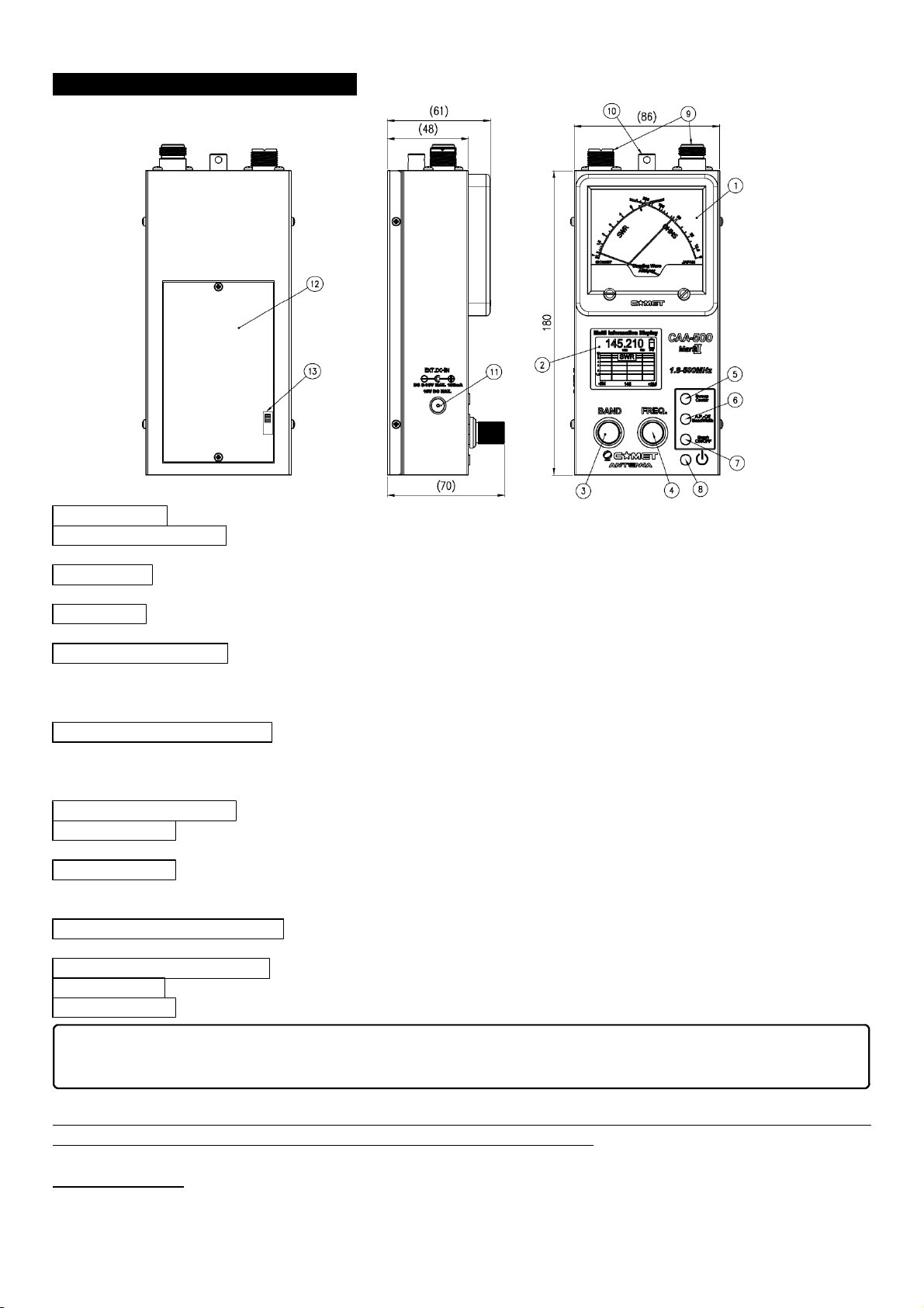
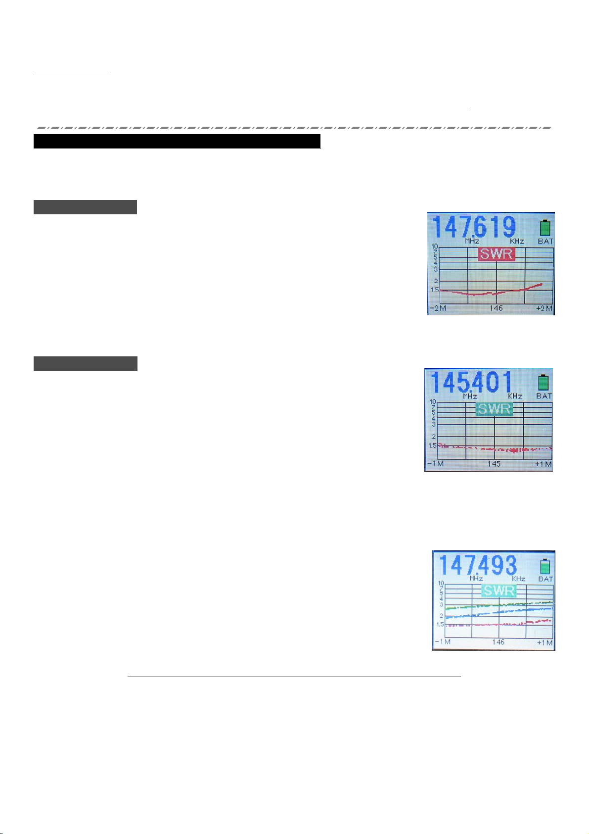
Q. Even with a known 50‐Ohm impedance, the SWR does not indicate a low value.
Ans. The impedance that you are viewing is an absolute value that also contains a reactance. It is possible to
have the meter show 50 Ohms of impedance without a 1:1 SWR.
Try to get the reactance as close to zero as possible; in this instance, with a total impedance of 50 Ohms and
nearly zero reactance, the SWR will be 1:1 (ideal situation).
In this MkII version, a reactance display has been added. Because it shows the absolute value of reactance (no
“+” or“‐”), you cannot initially tell if the reactance is capacitive or inductive. Generally, if the impedance is
capacitive ( ‐), then making the antenna shorter (in the case of a dipole or Yagi driven element) will cause the
reactance to increase. If the impedance is inductive ( + ), making the antenna longer will cause the reactance to
increase.
Q. At what point do I want to use a cable for attachment to the antenna?
Ans. To get the most accurate reading of the impedance, the meter should be either immediately at the
feedpoint for the antenna (often impossible) or connected via an integer multiple of a half wavelength of cable at
the frequency being measured. However, feedline loss may affect the results even in this case, so you will not
see the antenna performance alone, but rather the antenna + cable system performance.
When computing a half‐wavelength cable, the velocity factor of the cable must be included. For example, the
velocity factor of RG‐213 type coax is typically 67%. So for 14 MHz this is 492 x 12 (for inches) = 5904 divided by
14 (MHz) x 0.67 = 421.71 inches (including velocity factor).
Depending on the cable diameter and attendant losses, the use of cable lengths in excess of 30m (about 100’)
may yield inaccurate readings, due to the very low power of this unit.
Q.Is it possible to connect to the “M” (“UHF) and “N” (Type N) jacks simultaneously?
Ans. Because the jacks are automatically switched, according to the frequency in use, there is no way that both
jacks may be used simultaneously (the opposite connecter cannot be used in case of an incompatibility).
Notes on Handling
●This unit is fragile: do not drop or subject it to a strong shock.
Physical damage and/or malfunction may occur if unit is dropped.
●Do not use in very dusty or damp places, or outside in the rain.
This unit is not waterproof nor dustproof, so damage can occur if it is
exposed to spray, rain or severe dust.
●Please do not disassemble or modify this unit.
To do so may present danger due to electrical shock; product failure or failure to
meet specifications may occur if modified.
●Please use only at a temperature between 0º and +40º C (+32º to +104º F).
The Liquid Crystal Display (LCD) may malfunction at low temperatures.