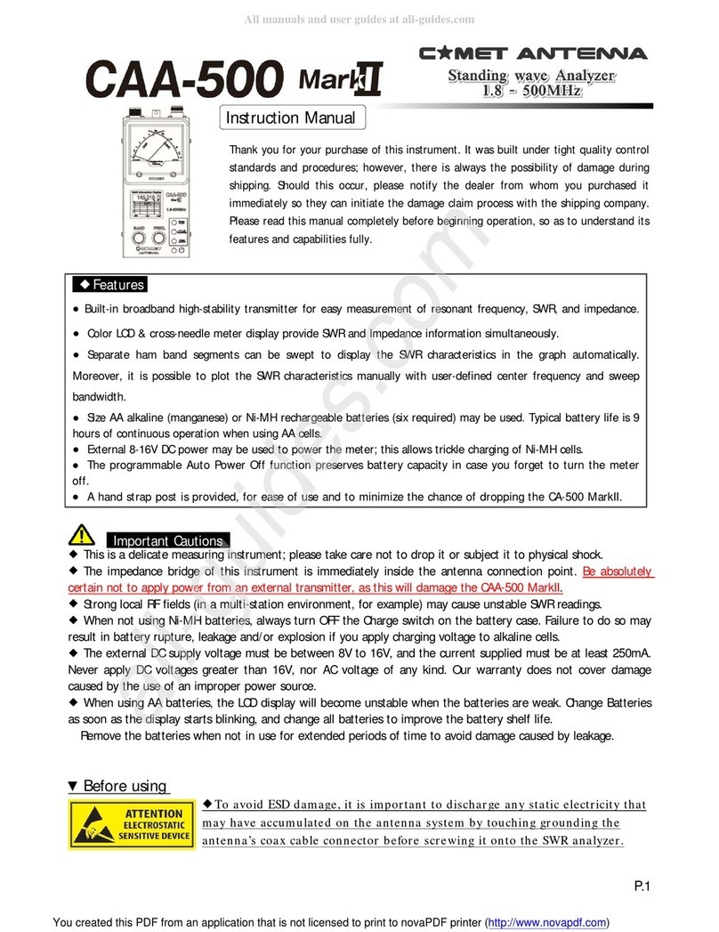
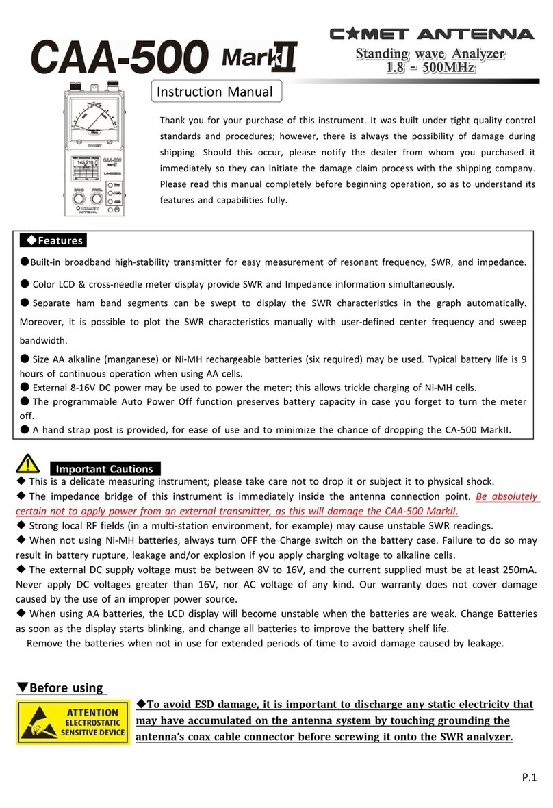
Comet Antenna CAA-500 Mark II User manual

-
1
/
8
-
Important Cautions
Important CautionsImportant Cautions
Important Cautions
◆
◆◆
◆
This is a delicate measuring instrument
This is a delicate measuring instrumentThis is a delicate measuring instrument
This is a delicate measuring instrument;
;;
; please take care not to drop it or subject it to physical shock.
please take care not to drop it or subject it to physical shock. please take care not to drop it or subject it to physical shock.
please take care not to drop it or subject it to physical shock.
◆
◆◆
◆
The impedance bridge of this instrument is immediately inside the antenna connection point. Because there is no
The impedance bridge of this instrument is immediately inside the antenna connection point. Because there is no The impedance bridge of this instrument is immediately inside the antenna connection point. Because there is no
The impedance bridge of this instrument is immediately inside the antenna connection point. Because there is no
protection for the bridge,
protection for the bridge, protection for the bridge,
protection for the bridge,
be absolutely certain not to apply power from an
be absolutely certain not to apply power from an be absolutely certain not to apply power from an
be absolutely certain not to apply power from an external transmitter
external transmitterexternal transmitter
external transmitter
.
..
.
◆
◆◆
◆
Strong local RF fields (in a multi
Strong local RF fields (in a multiStrong local RF fields (in a multi
Strong local RF fields (in a multi
station environment, for example) may cause unstable SWR readings.
station environment, for example) may cause unstable SWR readings.station environment, for example) may cause unstable SWR readings.
station environment, for example) may cause unstable SWR readings.
◆
◆◆
◆
In order to protect the detector elements in this unit, please be sure to discharge any static electricity buildup
In order to protect the detector elements in this unit, please be sure to discharge any static electricity buildup In order to protect the detector elements in this unit, please be sure to discharge any static electricity buildup
In order to protect the detector elements in this unit, please be sure to discharge any static electricity buildup
on the antenna by shorting the center pin of the connector on the coax line to ground before testing.
on the antenna by shorting the center pin of the connector on the coax line to ground before testing.on the antenna by shorting the center pin of the connector on the coax line to ground before testing.
on the antenna by shorting the center pin of the connector on the coax line to ground before testing.
◆
◆◆
◆
This unit is normally powered by six
This unit is normally powered by six This unit is normally powered by six
This unit is normally powered by six AA alkaline or NiMH cells. You may also apply external DC in the range of 8
AA alkaline or NiMH cells. You may also apply external DC in the range of 8AA alkaline or NiMH cells. You may also apply external DC in the range of 8
AA alkaline or NiMH cells. You may also apply external DC in the range of 8
16V.
16V. 16V.
16V.
The external DC supply shou
The external DC supply shouThe external DC supply shou
The external DC supply should be well regulated, and capabl
ld be well regulated, and capablld be well regulated, and capabl
ld be well regulated, and capable of at least 250 mA of current. Be absolutely certain
e of at least 250 mA of current. Be absolutely certain e of at least 250 mA of current. Be absolutely certain
e of at least 250 mA of current. Be absolutely certain
not to exceed the 16V maximum voltage limit. Do not apply AC
not to exceed the 16V maximum voltage limit. Do not apply AC not to exceed the 16V maximum voltage limit. Do not apply AC
not to exceed the 16V maximum voltage limit. Do not apply AC voltage of any kind.
voltage of any kind.voltage of any kind.
voltage of any kind.
◆
◆◆
◆
If using AA alkaline cells to power this unit, when the battery voltage becomes low the LCD display will falter
If using AA alkaline cells to power this unit, when the battery voltage becomes low the LCD display will falter If using AA alkaline cells to power this unit, when the battery voltage becomes low the LCD display will falter
If using AA alkaline cells to power this unit, when the battery voltage becomes low the LCD display will falter
and measurements will become unstable. Replace all six batteries with fresh ones (do not mix old and new). If you
and measurements will become unstable. Replace all six batteries with fresh ones (do not mix old and new). If you and measurements will become unstable. Replace all six batteries with fresh ones (do not mix old and new). If you
and measurements will become unstable. Replace all six batteries with fresh ones (do not mix old and new). If you
do not
do not do not
do not use the meter for a long time, remove the batteries to prevent damage from leakage.
use the meter for a long time, remove the batteries to prevent damage from leakage.use the meter for a long time, remove the batteries to prevent damage from leakage.
use the meter for a long time, remove the batteries to prevent damage from leakage.
■
■■
■
When not using NiMH batteries, please turn OFF the Charge switch on the battery case. Failure to do so might resu
When not using NiMH batteries, please turn OFF the Charge switch on the battery case. Failure to do so might resuWhen not using NiMH batteries, please turn OFF the Charge switch on the battery case. Failure to do so might resu
When not using NiMH batteries, please turn OFF the Charge switch on the battery case. Failure to do so might result
lt lt
lt
in battery rupture or leakage if you apply charging voltage to alkaline cells.
in battery rupture or leakage if you apply charging voltage to alkaline cells.in battery rupture or leakage if you apply charging voltage to alkaline cells.
in battery rupture or leakage if you apply charging voltage to alkaline cells.
●
●●
●
This product is intended for amateur radio measurement applications only (not certifiable professional testing).
This product is intended for amateur radio measurement applications only (not certifiable professional testing).This product is intended for amateur radio measurement applications only (not certifiable professional testing).
This product is intended for amateur radio measurement applications only (not certifiable professional testing).
Calibration of this unit for amateur applications is availa
Calibration of this unit for amateur applications is availaCalibration of this unit for amateur applications is availa
Calibration of this unit for amateur applications is available (fee will apply).
ble (fee will apply).ble (fee will apply).
ble (fee will apply).
Instruction Manual
Instruction ManualInstruction Manual
Instruction Manual
Thank you for your purchase of this instrument. It was built under tight quality
control standards and procedures; however, there is always the possibility
of damage during shipping. Should this occur, please notify the dealer from
whom you purchased it immediately so they can initiate the damage claim process
with the shipping company. Please read this manual completely before beginning
operation, so as to understand its features and capabilities fully.
◆
◆◆
◆
Features
FeaturesFeatures
Features
●The CA-500 MarkII has a wide-range signal oscillator covering 1.8-500 MHz enabling measurement of important antenna system
parameters including impedance and Standing Wave Radio (SWR).
●
The dual analog meter, combined with the LCD display, allows simultaneous display of SWR and impedance.
●
The color TFT display permits easy iewing of frequency and band information, e en in the dark.
●
The Band Sweep function allows you to measure SWR across the selected ham band and iew it on the display graph.
You can also define a center frequency and frequency span for display of the SWR characteristics.
●
The programmable Auto Power Off function preser es battery capacity in case you forget to turn the meter off.
●
You can use 6 AA alkaline or Nickel-Metal Hydride (NiMH) batteries to power the meter. Up to ten hours of operation
are possible using alkaline AA cells.
●
External 8-16V DC power may be used to power the meter; this also allows trickle charging of a NiMH battery.
●
A hand strap is pro ided, for ease of use and to minimize the chance of dropping the CA-500 MarkII.
All manuals and user guides at all-guides.com

-
2
/
8
-
◆
Panel/Case Parts and Descriptions
Panel/Case Parts and Descriptions Panel/Case Parts and Descriptions
Panel/Case Parts and Descriptions
①
isplay Meter
This Cross Meter displays both SWR and Impedance simultaneously
.
②
Multi-function isplay
The color LCD (Liquid Crystal Display shows frequency, amateur band, and SWR data
(impedance (Z /resistance (R /reactance (X and also can provide a swept-frequency SWR graph.
③BAND
Knob
This knob is used to select the frequency band within the range 1.8 to 500 MHz. Clockwise rotation of this
knob selects a higher frequency band. It is also used for setting of the APO (Automatic Power Off function.
④FREQ.
Knob
This knob is used to set the frequency within the selected amateur band. Clockwise rotation increases the
frequency, while counter-clockwise rotation lowers the frequency.
⑤SWEEP/CENTER
Button
In the
“
Normal
”
mode, pressing this button starts an SWR sweep of the band.
・When in the SWR Graph mode, pressing this button sets the current display frequency to be the center frequency of the
graph. In this mode, rotate the (3 BAND knob to adjust the Sweep width; press the (6 A.P.OFF/WIDTH button to confirm.
Now rotate the (4 FREQ knob to display the SWR plot.
⑥A.P.-OFF/BANDWIDTH
Button In the
“
Normal
”
mode, press and hold in this button for three seconds to
allow setting of the Auto Power Off feature
’
s time interval.
・
In the
“
Manual
”
plot mode, pressing t his
button allows you to set the bandwidth of the SWR Sweep.
・
While in the
“
Manual
”
plot mode, pressing this
button allows you to change the color of the SWR Graph.
⑦ GRAPH ON/OFF
Button
Press this button to switch between the
“
Normal
”
mode and the SWR Graph modes.
⑧ POWER
Button
This is the main P ower On/Off button for this device . Press once t o turn th e unit on,
and again to turn it off.
⑨
RF Connectors These are the coaxial jacks used for connection to the coaxial cable. The left connector
is an
“
M (
“
UHF
”
) type (used for 1.8-300 MHz), while the right jack is Type N, used for 300-500 MHz. Switching
is automatic, based on the Band setting.
⑩
Hand Strap Mounting Bracket
You may connect a commercially-available hand s trap here. As the diameter
of the mounting hole is greater than 1 mm, a sturdy strap (highly recommended) may be attached
.
⑪
External C Power Terminal
External C (8-16V) may be connected here. The center pin is positive (+).
⑫
Battery Case
This is the housing for six AA cells. Please install them according to the inscription
inside the case.
⑬
Charge S witch (Inside Battery Case) This is t he switch for enabling/disabling trickle charging of NiMH
cells, if used.
(※
Trickle charging is useful to help maintain a full charge on your battery by compensating for the slight
self-discharge that can occur even without a load being placed on the batteries
Before You Start
Before You StartBefore You Start
Before You Start
This instrument has been calibrated with the unit lying horizontally, with the meter facing up.
This instrument has been calibrated with the unit lying horizontally, with the meter facing up.This instrument has been calibrated with the unit lying horizontally, with the meter facing up.
This instrument has been calibrated with the unit lying horizontally, with the meter facing up. The
The The
The
discussion below is an operating example
discussion below is an operating examplediscussion below is an operating example
discussion below is an operating example;
;;
; the parameters you set may affect the actual results.
the parameters you set may affect the actual results. the parameters you set may affect the actual results.
the parameters you set may affect the actual results.
When using Alkaline or similar batteries
When using Alkaline or similar batteriesWhen using Alkaline or similar batteries
When using Alkaline or similar batteries, be sure to set this switch to the OFF position. In the event of battery
, be sure to set this switch to the OFF position. In the event of battery , be sure to set this switch to the OFF position. In the event of battery
, be sure to set this switch to the OFF position. In the event of battery
leakage, serious damage to this unit may occur if the switch is set to ON during use.
leakage, serious damage to this unit may occur if the switch is set to ON during use.leakage, serious damage to this unit may occur if the switch is set to ON during use.
leakage, serious damage to this unit may occur if the switch is set to ON during use.
Always be sure that you connect your coaxial connector to the proper connector. If you are con
Always be sure that you connect your coaxial connector to the proper connector. If you are conAlways be sure that you connect your coaxial connector to the proper connector. If you are con
Always be sure that you connect your coaxial connector to the proper connector. If you are connected to the opposite
nected to the opposite nected to the opposite
nected to the opposite
c
cc
co
oo
on
nn
nn
nn
ne
ee
ec
cc
ct
tt
to
oo
or
rr
r,
,,
,
m
mm
me
ee
ea
aa
as
ss
su
uu
ur
rr
re
ee
em
mm
me
ee
en
nn
nt
tt
ts
ss
s
w
ww
wi
ii
il
ll
ll
ll
l
b
bb
be
ee
e
i
ii
im
mm
mp
pp
po
oo
os
ss
ss
ss
si
ii
ib
bb
bl
ll
le
ee
e
a
aa
an
nn
nd
dd
d
i
ii
if
ff
f
t
tt
th
hh
he
ee
e
w
ww
wr
rr
ro
oo
on
nn
ng
gg
g
c
cc
co
oo
on
nn
nn
nn
ne
ee
ec
cc
ct
tt
to
oo
or
rr
r
i
ii
is
ss
s
u
uu
us
ss
se
ee
ed
dd
d,
,,
,
d
dd
da
aa
am
mm
ma
aa
ag
gg
ge
ee
e
t
tt
to
oo
o
t
tt
th
hh
he
ee
e
j
jj
ja
aa
ac
cc
ck
kk
k
m
mm
ma
aa
ay
yy
y
o
oo
oc
cc
cc
cc
cu
uu
ur
rr
r.
..
.
All manuals and user guides at all-guides.com

-
3
/
8
-
▲
▲▲
▲OPERATION
OPERATIONOPERATION
OPERATION
It is helpful to review operation before commencing operation. Steps (1) and (3) may be omitted
once you have verified that the unit is operating properly.
①
Connect a 5 -Ohm dummy load (not supplied) to the
“
M
”
(
“
UHF
”
) jack.
② Press the POWER switch to turn the unit on in the Normal mode.
Normal Mode Display Screen
Battery Level Meter
(※2,3)
波数表示
電池残量
Band Scale
The amateur bands 1.8-430 MHz are shown with a blue band
band (※1
.
Red underscore shows current band.
SWR Scale and Bar
The SWR is displayed graphically and numerically
Here. The SWR is shown to two decimal places.
OHMS Scale and Bar
The resistive component of the impedance is shown both
on the bar graph and numerically. Impedance (R, X) is
also displayed numerically.
※1 Note that not all the annotated amateur radio bands are available in all countries.
※2.
If using Nickel-Metal Hydride batteries, the battery status meter will ne er show
“
Full.
”
You should recharge
the batteries once the Yellow indication appears. If using alkaline cells, replace when the Yellow indicator appears.
③
When connected to a 5 -Ohm dummy load, the SWR indication should be 1.1 or less. If so, the meter
is performing correctly.
④
Perform measurements according to the discussion below.
▼
S
SS
SW
WW
WR Measurement
R MeasurementR Measurement
R Measurement
●
Connect the coaxial cable to the meter; use the shortest possible cable between the antenna and
meter, as any cable between the antenna and meter can transform the measured impedance, and feedline
loss can also cause the displayed SWR to be better than it actually is. See FAQ later.
●
Set the BAND and FREQ knobs to the band and frequency to be tested on the antenna.
●
You may now read the SWR and resistive value of impedance (OHMS) on the display. If there is
a su tle difference etween the mechanical and the LCD, the precision of the mechanical meter
has priority.
About the Reactance Display
About the Reactance DisplayAbout the Reactance Display
About the Reactance Display
The display of impedance on the LCD includes oth resistive (R) and reactance (X) indications.
Note that the X display is a solute value, so the polarity (+ or -) cannot e viewed.
▼
Measurement of Antenna Resonant Frequency
Measurement of Antenna Resonant FrequencyMeasurement of Antenna Resonant Frequency
Measurement of Antenna Resonant Frequency
■
Connect the antenna to the appropriate antenna connector on the meter, using the shortest possible
cable. If you use a long cable, the measurement will also include the effects of feedline loss, and
impedance differences between the antenna system and coaxial cable will not show the actual antenna
impedance.
■
While watching the frequency display, rotate the FREQ knob while observing SWR. If you rotate the
FREQ knob to the point where the frequency no longer changes, change the Band to set a new range.
■
The frequency at which the minimum S R is observed is the resonant frequency for the system.
Incidentally. . .
Because of stray inductance and capacitance, it is possible for the meter to show a
“
quasi
”
resonant
frequency. If the measured
“
resonant
”
frequency is different from what you expected, inspect your
system for these possible issues, in addition to those mentioned previously.
Full charge
Nearly full
Battery low
Battery level
Critically low
All manuals and user guides at all-guides.com

-
4
/
8
-
◆
◆◆
◆
Using the raph Mode to Display SWR vs. Frequency
Using the raph Mode to Display SWR vs. FrequencyUsing the raph Mode to Display SWR vs. Frequency
Using the raph Mode to Display SWR vs. Frequency
There are two types of Graph mode on this meter. You may use a predetermined center frequency
and andwidth to perform an SWR sweep, and alternately you may set an ar itrary center frequency
and andwidth to perform a manual SWR sweep.
Auto Sweep Mode
(
“
SWR
”
caption around center of Graph shown in Red
)
1.
While in the Normal display mode, press the SWEEP/CENTER utton to
initiate an automatic sweep. The center frequency and sweep andwidth
will e ased on the Band that is currently selected.
2.
While the Sweep is in progress, the
“
SWR
”
caption will link. A and
Sweep typically takes a out 25 seconds to complete.
3.
Once the Sweep is completed, you may repeat the Sw eep as many times
as desired y just pressing the SWEEP/CENTER utton again.
4.
To return to the Normal Mode, press the GRAPH ON/OFF utton. Note
that the FREQ and BAND kno s are disa led in the Sweep Mode.
Manual Plot Mode
(
“
SWR
”
caption around center of Graph shown in Green
)
1.
While in the Normal display mode, press the GRAPH ON/OFF utton to
enter the Manual Plot mode.
2.The S R Graph will now be displayed; use the BAND and FREQ knobs to set
the desired center frequency for the manual S R Sweep.
3.Press the S EEP/CENTER button.
The center frequency (rounded to three digits) will appear in the center
of the Graph, and the Sweep Limits (left a nd right at ottom) will link.
4.Use the BAND and/or FREQ knobs to set the Sweep bandwidth, then press
the A.P.OFF button to confirm the setting.
・Because the BAND knob causes huge frequency shift, generally you will use the FREQ knob to set Sweep Limits.
5.
After the setup is finalized, rotate the FREQ knob to perform the Manual Sweep. Gradual rotation
of the FREQ knob allows precision measuring to be performed (minimum resolution 1 kHz).
6.
If you press the AP-OFF button during a Manual Sweep, the color of the plot
will change (Red -> Blue -> Green -> Purple -> Orange -> Red. . .).
7.
If you want to change t he bandwidth in this mode, press the SWEEEP/CENTER
button again.
8.
To return to the Normal mode, press the GRAPH On/OFF u tton.
Note: You can not preserve the raph data if you change raph Modes
Note: You can not preserve the raph data if you change raph ModesNote: You can not preserve the raph data if you change raph Modes
Note: You can not preserve the raph data if you change raph Modes
●
●●
●
Setting the Auto Power Off Time
Setting the Auto Power Off TimeSetting the Auto Power Off Time
Setting the Auto Power Off Time
■
This procedure sets the Auto Power Off timer, to preserve battery life after meter inactivity.
In the Normal mode, press and hold in the A.P.OFF button for more than three seconds; the currently-set
Auto Power Off time will be shown on the display. Rotate the BAND knob to change the timer in one-minute
increments (
–
9 minutes). When done, Press the A.P.OFF button momentarily.
●If the timer is set to 0 minutes, the Auto Power Off function will be disabled.
●
When power is turned off, this setting will be saved.
・
Note that the meter will consider frequency change of less than 3% to be
“
inactivity
”
when counting
down the Auto Power Off timer.
Auto Sweep Mode
Auto Sweep ModeAuto Sweep Mode
Auto Sweep Mode
Manual Plot Mode
Manual Plot ModeManual Plot Mode
Manual Plot Mode
Rotate the BAND
knob to change
the APO time.
All manuals and user guides at all-guides.com

-
5
/
8
-
Quick
QuickQuick
Quick-
--
-Reference
ReferenceReference
Reference
Operation
OperationOperation
Operation
Chart
ChartChart
Chart
Power
Power Power
Power
ON
ONON
ON
●Regarding the Charging and Use of Nickel-Metal Hydride (NiMH) Batteries
・
This meter can be used either with alkaline or NiMH rechargeable batteries.
・
If using NiMH batteries, they may be trickle charged inside the case.
・
To trickle charge NiMH batteries, you must set the small slide switch inside the case (near the battery
holder) to the CHARGE ON position.
■
When the battery level indicator changes from yellow to red, apply 12-14V DC to the DC IN jack to
trickle charge the NiMH batteries. A full charge takes about 14-15 hours.
■
Charging of NiMH cells can be done with as little as 8V DC, but it may take several dozen hours
to achieve a full charge. If the DC voltage is above 14V, the batteries may charge, but their lifetime
will be shortened.
・
Trickle charging will occur, regardless of the setting of the Power On/Off Switch, if 12-14V DC is
present at the DC IN jack.
・
The trickle charge current is very low, but we recommend that you turn off and disconnect the DC
power source used for charging if you will be away from the unit for a long time.
●About Error Messages
If an error occurs during Sweep operation, an error message will appear at
the top right. In this case, ER1 indicates that the f requency of interes t could
not be set.
Frequently, very strong local RF fields can cause erratic meter operation and/or
incorrect SWR readings.
Try to eliminate the strong RF fields
and try again.
If ER1 appears even with no antenna connected, there may be an internal
malfunction in the meter. Contact your dealer for repair assistance.
SWR
SWRSWR
SWR
& Resonant Frequency Measurement Mode
& Resonant Frequency Measurement Mode & Resonant Frequency Measurement Mode
& Resonant Frequency Measurement Mode
GRAPH ON/OFF
Button
SWEEP/CENTER
Button
Auto Sweep Mode
Auto Sweep ModeAuto Sweep Mode
Auto Sweep Mode
Manual Plot Mode
Manual Plot ModeManual Plot Mode
Manual Plot Mode
SWEEP/CENTER
Button
GRAPH ON/OFF
Button
Set Center Frequency & Bandwidth
Set Center Frequency & BandwidthSet Center Frequency & Bandwidth
Set Center Frequency & Bandwidth
Confirm w/A.P. Off Button
Turn FREQ Knob to
Turn FREQ Knob to Turn FREQ Knob to
Turn FREQ Knob to
GRAPH ON/OFF
Button
Be certain to turn the charging slide switch to OFF when using alkaline cells!
Be certain to turn the charging slide switch to OFF when using alkaline cells!Be certain to turn the charging slide switch to OFF when using alkaline cells!
Be certain to turn the charging slide switch to OFF when using alkaline cells!
If you neglect to turn this switch off, and attempt to charge alkaline cells, battery leakage
If you neglect to turn this switch off, and attempt to charge alkaline cells, battery leakage If you neglect to turn this switch off, and attempt to charge alkaline cells, battery leakage
If you neglect to turn this switch off, and attempt to charge alkaline cells, battery leakage
may occur, which can cause serious dama
may occur, which can cause serious damamay occur, which can cause serious dama
may occur, which can cause serious damage to this unit (not covered by our Limited Warranty).
ge to this unit (not covered by our Limited Warranty).ge to this unit (not covered by our Limited Warranty).
ge to this unit (not covered by our Limited Warranty).
Also, do not use a combination of alkaline and NiMH batteries, as damage can occur in case of
Also, do not use a combination of alkaline and NiMH batteries, as damage can occur in case of Also, do not use a combination of alkaline and NiMH batteries, as damage can occur in case of
Also, do not use a combination of alkaline and NiMH batteries, as damage can occur in case of
an unexpected accident.
an unexpected accident.an unexpected accident.
an unexpected accident.
All manuals and user guides at all-guides.com

-
6
/
8
-
Recovery Procedures
Recovery ProceduresRecovery Procedures
Recovery Procedures
4.Press the CENTER key. An automatic adjustment process will begin; you will notice a number incrementing
upward.
6
. Now turn the CA-5 MarkII off.
FAQ –Frequently Asked Questions-
(Before Contacting Us)
Q.
Q. Q.
Q.
When the antenna connected,
When the antenna connected, When the antenna connected,
When the antenna connected, the resonant frequency appears shifted or there is no SWR dip.
the resonant frequency appears shifted or there is no SWR dip.the resonant frequency appears shifted or there is no SWR dip.
the resonant frequency appears shifted or there is no SWR dip.
A.
On an antenna not requiring radials, the case of this unit is the
“
ground
”
and it is possible, due to
common mode current flow or other reasons, that the meter may be situated in a position that causes radically
unusual readings to occur. Try to relocate the meter as close to the antenna as possible to see if this
eliminates the problem.
If ER2 appears immediately aftger powering up the unit,
it means that the internal flash data is corrupted.
1.Press and hold in the GRAPH ON/OFF key; while holding it
in, press the PO ER key to turn on the CA-500 MarkII.
・Release the GRAPH ON/OFF key when prompted.
・The version number for the unit’s firmware will; now appear
on the LCD.
2.
Now press the GRAPH ON/OFF key.
[BAND A] will e displayed.
3.
Press the GRAPH ON/OFF key again.
[AUTO: 1] will e displayed.
・Set the FREQ knob to the center of its range.。
・
Do not move the FREQ kno hereafter during
this procedure.
5.
After a out two minutes, [COMP:
35 will e displayed. The procedure
is now complete.
All manuals and user guides at all-guides.com

-
7
/
8
-
Q.
Q. Q.
Q.
Even with a known 50
Even with a known 50Even with a known 50
Even with a known 50
Ohm impedance, the SWR does not indicate a low value.
Ohm impedance, the SWR does not indicate a low value.Ohm impedance, the SWR does not indicate a low value.
Ohm impedance, the SWR does not indicate a low value.
A.
The impedance that you are viewing is an absolute value that also contains a reactance. It is possible
to have the meter show 50 Ohms of impedance without a 1:1 SWR.
Try to get the reactance as close to zero as possible; in this instance, with a total impedance of 50
Ohms and nearly zero reactance, the SWR will be 1:1 (ideal situation).
In this MkII version, a reactance display has been added. Because it shows the absolute value of reactance (no “+” or
“
- ” , you cannot initially tell if the reactance is capacitive or inductive. Generally, if the impedance is capacitive ( - ,
then making the antenna shorter (in the case of a dipole or Yagi driven element will cause the reactance to increase. If
the impedance is inductive ( + , making the antenna longer will cause the reactance to increase.
Q.
Q. Q.
Q.
At what point do I want to use a cable for attachment to the antenna?
At what point do I want to use a cable for attachment to the antenna?At what point do I want to use a cable for attachment to the antenna?
At what point do I want to use a cable for attachment to the antenna?
A.To get the most accurate reading of the impedance, the meter should be either immediately at the feedpoint for the
antenna (often impossible or connected via an integer multiple of a half wavelength of cable at the frequency being
measured. However, feedline loss may affect the results even in this case, so you will not see the antenna performance
alone, but rather the antenna + cable system performance.
When computing a half-wavelength cable, the velocity factor of the cable must be included. For example,
the velocity factor of RG-213 type coax is typically 67%. So for 14 MHz this is 492 x 12 (for inches) =
5904 divided by 14 (MHz) x 0.67 = 421.71 inches (including velocity factor).
Depending on the cable diameter and attendant losses, the use of cable lengths in excess of 30m (about 100’ may yield
inaccurate readings, due to the very low power of this unit.
Q.Is it possible to connect to the “M” (“UHF) and “N” (Type N) jacks si ultaneously?
Q.Is it possible to connect to the “M” (“UHF) and “N” (Type N) jacks si ultaneously?Q.Is it possible to connect to the “M” (“UHF) and “N” (Type N) jacks si ultaneously?
Q.Is it possible to connect to the “M” (“UHF) and “N” (Type N) jacks si ultaneously?
A.
Because the jacks are automatically switched, according to the frequency in use, there is no way that
both jacks may be used simultaneously (the opposite connecter cannot be used in case of an incompatibility).
◆
◆◆
◆Product Specifications
Product SpecificationsProduct Specifications
Product Specifications
Frequency Range 1.8
–
5 MHz in 35 range segments
RF Output Level dBm (1 mW)
Measured SWR Range Analog Meter: 1.
–
6. ; LCD:1.
–
9.9
Impedance Range 12.5
–
3 Ohms (Analog and LCD)
Resistance Range 1
–
5 Ohms
Reactance Range
–
5 Ohms (Absolute Value)
RF Connectors
“
M
”
(
“
UHF/SO-239
”
) for HF/VHF,
“
N
”
for UHF
Operating Temp.
º
- 4
º
C (32
º
- 1 4
º
F)
Power Sources 6 x Alkaline or NiMH Rechargeable Cells
External Power: +8 to +16V DC
Current Consumption
185 mA or less
Charging Time 15 hours at 12
–
14V DC (trickle charge)
Dimensions 89 (W) x 196 (H) x 7 (H) mm (incl. knobs/jacks)
Weight 8 g (unit only), 94 g (w/batteries)
Supplied Accessory External DC Cable (Center pin +)
Notes on Handling
Notes on HandlingNotes on Handling
Notes on Handling
●
This unit is fragile: do not drop or subject it to a strong shock.
This unit is fragile: do not drop or subject it to a strong shock.This unit is fragile: do not drop or subject it to a strong shock.
This unit is fragile: do not drop or subject it to a strong shock.
Physical damage and/or malfunction may occur if unit is dropped.
●
Do not use in very dusty or damp places,
Do not use in very dusty or damp places, Do not use in very dusty or damp places,
Do not use in very dusty or damp places, or outside in the rain.
or outside in the rain.or outside in the rain.
or outside in the rain.
This unit is not waterproof nor dustproof, so damage can occur.
●
Please do not disassemble or modify this unit.
Please do not disassemble or modify this unit.Please do not disassemble or modify this unit.
Please do not disassemble or modify this unit.
To do so may present danger due to electrical shock;
product failure or failure
to meet specifications may occur if modified
。
●
Please use only at a te perature between 0
Please use only at a te perature between 0Please use only at a te perature between 0
Please use only at a te perature between 0
º
and +40
and +40 and +40
and +40
º
C (+32
C (+32 C (+32
C (+32
º
to +104
to +104 to +104
to +104
º
F).
F). F).
F).
The Liquid Crystal isplay (LC ) may malfunction at low temperatures.
All manuals and user guides at all-guides.com

-
8
/
8
-
For After
For AfterFor After
For After-
--
-sale Service
sale Servicesale Service
sale Service
●
For questions about this product, contact your dealer or our Technical Support staff
◆
For repairs or in case of shipping damage, consult the dealer from whom this unit was purchased.
■
For further information about our Limited Warranty, please consult the warranty card supplied with
this unit.
Specifications for this product are subject to change without notice or obligation, in the interest of
ongoing product improvement.
1st edition. May 2015
Copyright (C) 2015 COMET CO LTD. All Rights Reserved.
COMET CO., TD.
COMET CO., TD.COMET CO., TD.
COMET CO., TD.
Tsuji 4-18-2 Minami-ku Saitama-City Saitama 336-0026 JAPAN
TEL: +81 048-839-3131 FAX: +81 048-839-3136
URL http://www.comet-ant.co.jp
All manuals and user guides at all-guides.com
Table of contents
Other Comet Antenna Measuring Instrument manuals