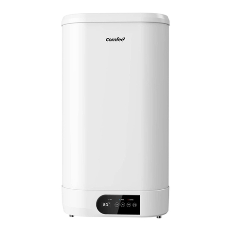
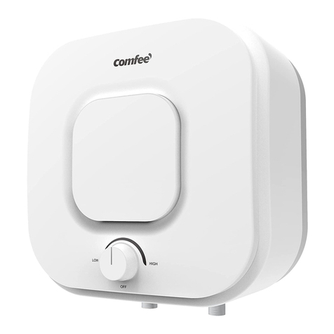
Comfee D30-15FGC User manual

Storage Electric Water Heater
The diagram above is just for reference. Please take the
appearance of the actual product as the standard.
Instruction Manual
For Model:
Thank you very much for purchasing our water heater.
Before installing and operating your water heater, please
read this manual carefully and keep it for future reference.
D30-15FGC
D50-15FGC
D80-15FGC
D80-15FGC(H)

1
The installation and maintenance has to be carried out by qualified professials or Midea
authorized technicians.
The manufacturer shall not be held responsible for any damage or malfunction caused by wrong
installation or failing to comply with following instructions included in this pamphlet.
For more detailed installation and maintenance guidelines, please refer to below chapters.
TABLE OF CONTENTS
TITLE PAGE
1.Cautions ...........................................................................................................................(2)
2.Product introduction .........................................................................................................(3)
3.Unit installation .................................................................................................................(5)
4.Methods of using ..............................................................................................................(7)
5.Maintenance.....................................................................................................................(8)
6.Troubleshooting................................................................................................................(9)
●
●
●
General Remark

2
The supply socket must be earthed reliably. The rated current of the socket shall not be lower
than 10A. The socket and plug shall be kept dry to prevent electrical leakage.
The installation height of the supply socket shall not be lower than 1.8m.
The wall in which the electrical water heater is installed shall be able to bear the load more than
two times of the heater filled fully with water without distortion and cracks. Otherwise, other
strengthening measures shall be adopted.
The pressure relief valve attached with the heater must be installed at the cold water inlet of this
heater(see Fig.1).
Before installing this water heater,check and confirm that the earthing on the supply socket is
reliably grounded. Otherwise, the electrical water heater can not be installed and used. Do not
use extension boards. Incorrect installation and use of this electrical water heater may result in
serious injuries and loss of property.
Special Cautions
Hot water
1. CAUTIONS
●
●
●
●
●
●
●
●
●
●
Cold water
(Fig.1)
Pressure relief valve
Thread screw
Drain handle
Pressure release hole
When using the heater for the first time(or the first use after maintenance), the heater can not be
switched on until it has been filled fully with water. When filling the water, at least one of the outlet
valves at the outlet of the heater must be opened to exhaust the air. This valve can be closed
after the heater has been filled fully with water.
The water heater is not intended for use by persons(including children)with reduced physical,
sensory or mental capabilities, or lack of experience and knowledge, unless they have been
given supervision or instructions concerning use of the appliance by a person responsible for
their safety. Children should be supervised to ensure that they do not play with the heater.
During heating, there may be drops of water dripping from the pressure release hole of the
pressure relief valve. This is a normal phenomenon. If there is a large amount of water leak,
please contact customer care center for repair. This pressure release hole shall, under no
circumstances, be blocked; otherwise, the heater may be damaged, even resulting in accidents.
The drainage pipe connected to the pressure release hole must be kept sloping downwards.
Since the water temperature inside the heater can reach up to 75
°C
, the hot water must not be
exposed to human bodies when it is initially used. Adjust the water temperature to a suitable
temperature to avoid scalding.
If the flexible power supply cord is damaged, the special supply cord provided by the manufacturer
must be selected, and replaced by the professional maintenance personnel.

3
2. PRODUCT INTRODUCTION
2.1 Nomenclature
D -
NOTE
This manual is applicable to the storage electric water heaters (D *-***) manufactured by
this company.
is the product code of the storage electric water heater;
is the capacity (L);
represents the rated power (*100W);
represents the pattern code (eg : A,B,C...);
represents the extension of pattern (eg : 1,2,3...);
①
①
②
②
③
③
④
④
⑤
⑤
Model
Rated
Voltage
(ACV)
IPX4
IPX4
IPX4
80
80
80
0.8
0.8
0.8
220-240
220-240
220-240
220-240
1500
1500
1500
1500
27
47
74
Rated
Power
(W)
Volume
(L)
Rated
Pressure
(MPa)
Max Of Water
Temperature
(°C)
Protection
Class Waterproof
Grade
2.2 Technical Performance Parameters
I
I
I
IPX4800.874 I
●
●
●
●
●
If any parts and components of this electrical water heater are damaged please contact customer
care center for repair.
This appliance is not intended for use by persons (including children) with reduced physical,
sensory or mental capabilities, or lack of experience and knowledge, unless they have been
given supervision or instruction concerning use of the appliance by a person responsible for
their safety.
Children should be supervised to ensure that they do not play with the appliance.
The water may drip from the discharge pipe of the pressure-relief device and that this pipe must
be left open to the atmosphere; The pressure-relief device is to be operated regularly to remove
lime deposits and to verify that it is not blocked;
In order to drain away the water inside the inner container, it can be drained away from the
pressure release valve. Twist the thread screw of the pressure release valve off, and lift the drain
handle upwards.(See Fig.1) A discharge pipe connected to the pressure-relief device is to be
installed in a continuously downward direction and in a frost-free environment.
D30-15FGC
D50-15FGC
D80-15FGC
D80-15FGC(H)

4
2.3 Brief introduction of product structure
2.4 Internal Wire Diagram
(Note:All dimensions are in mm)
B
AC
WIRING DIAGRAM
E
N
L
QQ
Heating Element
Thermal
Cut Out Thermostat
Brown
Blue
Yellow/Green
Heating indicator light
D1
D2
A
B
C
D1
27L
340
340
278
47L
385
385
278
74L
450
450
278
610 755 812
D2 130-310 130-310 130-310

3.1 Installation Instruction
①
②
③
④
3. UNIT INSTALLATION
5
This electrical water heater shall be installed on a solid wall. If the strength of the wall
cannot bear the load equal to two times of the total weight of the heater filled fully with
water, it is then necessary to install a special support.
Incase of hollow bricks wall, ensure to fill it with cement concrete completely.
After selecting a proper location, determine the positons of the two install holes used for
expansion bolts with hook (200mm), Make two holes in the wall with the corresponding
depth by using a chopping bit with the size matching the expansion bolts attached with the
machine, insert the screws, make the hook upwards, tighten the nuts to fix firmly, and then
hang the electrical water heater on it (see Fig.2).
Install the supply socket in the wall. The requirements for the socket are as follows: 250V/10A,
single phase, three electrodes. It is recommended to placed the socket on the right above
the heater. The height of the socket to the ground shall not be less than 1.8m (see Fig.3).
If the bathroom is too small, the heater can be installed at another place. However, in
order to reduce the pipeline heat losses, the installation position of the heater shall be
closed to the location shall be as near as possible to the heater.
(Fig.2)
(Fig.3)
N (Blue) Ground
≥1.8m
L (Brown) E (Yellow/Green)
※ When the second hanging plate is used for installation, it is preferred to install in the hole
(Dimension: D1). If it is installed in the lower part (dotted line position), it is necessary to confirm
whether it is firm after completion(Dimension: D2)
Expansion
bolt (with hook)
Wall hanging type 2
Wall hanging type 1

3.2 Pipelines Connection
If the users want to realize a multi-way supply system, refer to the method shown in fig.5
for connection of the pipelines.
④
6
①
②
③
The dimension of each pipe part is G1/2” .
Connection of pressure relief valve with the heater on the inlet of the water heater.
In order to avoid leakage when connecting the pipelines, the rubber seal gaskets provided
with the heater must be added at the end of the threads to ensure leak proof joints (see
Fig.4).
(Fig.4)
(Fig.5)
Pressure relief valve
Water inlet valve
Water inlet valve
Running water pipeMixing valve
Water pool
Triple joint Shower nozzle
Hot water outlet Cold water inlet
Pressure relief valve
Pressure release hole
Joint screw for cold water inlet
Adjusting handle for
mixing valve Hot water
Hot water
outlet Cold water
inlet

NOTE
Please be sure to use the accessories provided by our company to install this electric
water heater. This electric water heater can not be hung on the support until it has been
confirmed to be firm and reliable. Otherwise, the electric water heater may drop off from
the wall, resulting in damage of the heater, even serious accidents of injury. When
determining the locations of the bolt holes, it shall be ensured that there is a clearance
not less than 0.2m on the right side of the electric heater, to convenient the maintenance
of the heater, if necessary.
7
4. METHODS OF USING
NOTE
During normal operation, the inlet valve shall be always kept open.
First, open any one of the outlet valves at the outlet of the water heater, then, open the inlet
valve. The water heater gets filled with water. When water flows out of the outlet pipe it implies
that the heater has been filled fully with water, and the outlet valve can be closed.
Insert the supply plug into the supply socket, the indicator will light up this time.
The thermostat will automatically control the temperature. When the water temperature inside
the heater has reached the set temperature, it will switch off automatically, when the water
temperature falls below the set point the heater will be turned on automatically to restore the
heating.
●
●
●
①
Temperature knob:
●Turn the knob to adjust the temperature. The temperature increases when turning right and
decreases when turning left
1
②
2
Heating indicator:
●When the product is heated, the lamp is on, and when the heating is completed, the lamp
is off
③
●When the knob indicates Eco, the product temperature is set to about 55 °
●When the knob is turned to the icon, the product is set to 80 °, and more hot water can
appear
④
1
2
L
O
W

8
●
Check the power plug and outlet as often as possible. Secure electrical contact and also proper
grounding must be provided. The plug and outlet must not heat excessively.
If the heater is not used for a long time, especially in regions with low air temperature(below 0℃),
it is nessary to drain water from the heater to prevent damage of the water heater, due to water
freezing in the internal tank.(Refer Cautions in this manual for the method to drain away the water
from the inner container).
To ensure long reliable water heater operation, it is recommended to regularly clean the internal
tank and remove deposits on the electric heating element of the water heater, as well as check
condition (fully decomposed or not) of the magnesium anode and, if necessary, replace it with a
new one in case of full decomposition.Tank cleaning frequency depends on hardness of water
located in this territory. Cleaning must be performed by special maintenance services. You can
ask the seller for address of the nearest service center.
●
●
●
WARNING
Before doing any maintenance, please cut off the power supply.
!
WARNING
Non-professionals are not allowed to disassemble the thermal switch to reset.
Please contact prefessionals to maintain. Otherwise our company will not take
responsiblity if any quality accident happens because of this.
!
The water heater is equipped with a thermal switch, which cuts off power supply of the heating element
upon water overheating or its absence in the water heater. If the water heater is connected to the mains,
but water is not heated and the indicator doesn’t light up, then the thermal switch was switched off or not
switched on. To reset the water heater to the operating condition, it is necessary to:
1. De-energize the water heater, remove the plate of the side/lower cover.
2. Press the button, located at the center of the thermal switch, see Fig.6;
3. If the button is not pressed and there is no clicking, then you should wait until the thermal switch
cools down to the initial temperature.
(Fig.6)
Manual reset button
5. MAINTENANCE

6. TROUBLESHOOTING
9
NOTE
Parts illustrated in this use and care manual are indicative only, parts provided with the
product may differ with illustrations. This product is intended for household use only.
Specifications are subject to change without notice.
Failures Reasons Treatment
The heating indicator
light is off.
Failures of the temperature
controller.
Contact with the professional
personnel for repair.
No water coming out
of the hot water outlet.
The water temperature
is too high.
Water leak.
1. The running water supply
is cut off.
2. The hydraulic pressure is
too low.
3. The inlet valve of running
water is not open.
1. Wait for restoration of
running water supply.
2. Use the heater again when
the hydraulic pressure is
increased.
3. Open the inlet valve of
running water.
Failures of the temperature
control system.
Seal problem of the joint
of each pipe.
Contact with the professional
personnel for repair.
Seal up the joints.

10

The product is subject to change without notice.
Please keep this manual properly.
Wuhu Midea Kitchen & Bath Appliances Mfg. Co., Ltd.
Address: East Road Wanchun, East Area Economic & Technological
Development Area, Wuhu City, Anhui Province, P.R.China.
Web site: www.midea.com/global Postal code: 241000
Midea Italia S.r.l. a socio unico:
Viale Luigi Bodio 29/37
20158 Milano Italia
midea.com/it

Storage Electric Water Heater
L'immagine sopra indicativa e ha il solo scopo di descrivere il prodotto.
Considerare le informazioni del manuale e le specifiche di
riferimento per le informazioni effettive.
Manuale utente e di installazione
Modelli: D30-15FGC
D50-15FGC
D80-15FGC
D100-15FGC(H)
Grazie per aver acquistato uno scaldacqua Midea! Questo prodotto
conforme ai pi elevati standard di qualit disponibili. Prima di installare
ed utilizzare il prodotto, leggere questo manuale e conservarlo per le
future necessit di consultazione.

1
Titolo Pagina
1.Precauzioni.......................................................................................................................(2)
2.Introduzione al prodotto....................................................................................................(3)
3.Installazione dell'unità ......................................................................................................(5)
4.Metodi di utilizzo ..............................................................................................................(7)
5.Manutenzione...................................................................................................................(8)
6.Risoluzione dei problemi ..................................................................................................(9)
●
●
●
L'installazione e la manutenzione del prodotto devono essere effettuate da personale qualificato
o da centri assistenza tecnica autorizzati da Midea.
Il produttore non deve essere ritenuto responsabile per qualsiasi danno o malfunzionamento
causato da installazione errata o dal mancato rispetto delle istruzioni incluse in questo libretto.
Per maggiori informazioni sulle condizioni di installazione e manutenzione dei prodotti, fare
riferimento a quanto segue.
Indicazioni generali
INDICE

2
La presa di alimentazione deve essere collegata a terra in modo affidabile. La corrente nominale
della presa non deve essere inferiore a 10 A. La presa e la spina devono essere mantenute
asciutte per evitare dispersioni elettriche.
L'altezza di installazione della presa di alimentazione non deve essere inferiore a 1,8 metri.
La parete di installazione dello scaldabagno elettrico deve essere in grado di sostenere più di
due volte il carico dello scaldabagno riempito completamente d'acqua, senza subire distorsioni e
crepe. In caso contrario, dovranno essere adottate misure di rafforzamento.
La valvola di sicurezza fornita con lo scaldabagno deve essere installata all'ingresso dell'acqua
fredda dello stesso scaldabagno (vedere Fig. 1).
Prima di installare lo scaldabagno, controllare e confermare che la messa a terra della presa di
alimentazione sia affidabile. In caso contrario, lo scaldabagno elettrico non può essere installato
né utilizzato. Non utilizzare pannelli di estensione. L'installazione e l'uso non corretti dello
scaldabagno elettrico possono causare gravi lesioni e danni materiali.
Precauzioni speciali
acqua calda
1. PRECAUZIONI
●
●
●
●
●
●
●
●
acqua fredda
(Fig.1)
valvola di sicurezza
perno valvola
leva
foro uscita acqua
Quando si utilizza lo scaldabagno per la prima volta (o in caso di primo utilizzo dopo la manuten-
zione), lo scaldabagno non può essere acceso finché non è stato riempito completamente con
acqua. Durante il riempimento dell’acqua, almeno una delle valvole di scarico all’uscita dello
scaldabagno deve essere aperta per espellere l'aria. Questa valvola può essere chiusa dopo che
lo scaldabagno è stato riempito completamente con acqua.
Lo scaldabagno non è pensato per essere utilizzato da persone (compresi bambini) con capacità
fisiche, sensoriali o mentali ridotte, o non dotate dell'esperienza e delle conoscenze necessarie,
fatto salvo nel caso in cui siano sorvegliate o abbiano ricevuto le istruzioni necessarie per un uso
sicuro dell'apparecchio da parte di una persona responsabile della loro sicurezza. I bambini
devono essere sorvegliati per garantire che non giochino con lo scaldabagno.
Durante il riscaldamento, è possibile che dal foro di rilascio della pressione della valvola di
sicurezza fuoriescano gocce d'acqua. Si tratta di un fenomeno normale. In caso di perdite
d'acqua consistenti, contattare il centro assistenza clienti per la riparazione. Il foro di rilascio della
pressione non deve in alcun caso essere ostruito; in caso contrario, lo scaldabagno potrebbe
subire danni e causare possibili incidenti.
Il tubo di scarico collegato al foro di rilascio della pressione deve essere mantenuto in pendenza
verso il basso.

3
IPX4
IPX4
IPX4
80
80
80
0.8
0.8
0.8
220-240
220-240
220-240
220-240
1500
1500
1500
1500
27
47
74
I
I
I
IPX4800.874 I
●
●
●
●
●
●
●
Poiché la temperatura dell'acqua all'interno dello scaldabagno può raggiungere i 75 °C, l'acqua
calda non deve venire a contatto con il corpo al momento del primo utilizzo. Regolare la tempera-
tura dell'acqua a una temperatura adeguata, per evitare scottature.
Se il cavo di alimentazione flessibile è danneggiato, è necessario utilizzare il cavo di alimentazi-
one speciale fornito dal produttore e richiederne la sostituzione da parte del personale addetto
alla manutenzione.
Se le parti e i componenti dello scaldabagno elettrico sono danneggiati, contattare il centro
assistenza clienti per la riparazione.
Questo dispositivo non è pensato per essere utilizzato da persone (compresi bambini) con
capacità fisiche, sensoriali o mentali ridotte, o non dotate dell'esperienza e delle conoscenze
necessarie, fatto salvo nel caso in cui siano sorvegliate o abbiano ricevuto le istruzioni necessa-
rie per un uso sicuro dell'apparecchio da parte di una persona responsabile della loro sicurezza.
I bambini devono essere sorvegliati per garantire che essi non giochino con l'apparecchio.
L'acqua può gocciolare dal tubo di scarico del dispositivo di riduzione della pressione e il tubo
deve essere lasciato aperto all'atmosfera; il dispositivo di riduzione della pressione deve essere
azionato regolarmente per rimuovere i depositi di calcare e verificare che non sia bloccato.
Per scaricare l'acqua dentro al contenitore interno, è possibile farla defluire dalla valvola di
rilascio della pressione. Ruotare la vite filettata della valvola di rilascio della pressione e sollevare
la maniglia di scarico verso l'alto. (Vedere Fig. 1) Un tubo di scarico collegato al dispositivo di
riduzione della pressione deve essere installato in modo che sia costantemente rivolto verso il
basso e in un ambiente non esposto al rischio di gelo.
D30-15FGC
D50-15FGC
D80-15FGC
D80-15FGC(H)
2. Introduzione al prodotto
2.1 Nomenclatura
D -
NOTA
Questo manuale si riferosce esclusivamente ai prodotti commercializzati da Midea Italia
S.r.l. a socio unico.
①Codice prodotto: D = Scaldacqua elettrico
②capacità (L)
③Potenza elettrica (W Moltiplicato 100)
④Codice prodotto (es: A,B,C...);
⑤Serie produttiva (es: 1,2,3...)
①② ③ ④ ⑤
2.2 Dati tecnici prodotti
Modello
Tensione
Nominale
(VAC)
Potenza
Nominale
(W)
Volume
(L)
Pressione
(MPa)
Temperatura
(℃)Grado di
protezione
Classe di
protezione

4
2.4 Schema elettrico interno
B
AC
D1
D2
A
B
C
D1
27L
340
340
278
47L
385
385
278
74L
450
450
278
610 755 812
D2 130-310 130-310 130-310
SCHEMA ELETTRICO
E
N
L
QQ
2.3 Schemi dimensionali
(Nota: tutte le dimensioni sono in mm)
Interruzione
termica
Marrone
Blu
Giallo/Verde
Termostato
Indicatore di
riscaldamento
Elemento riscaldante

①
②
③
④
5
Lo scaldabagno elettrico deve essere installato su una parete solida. Se la resistenza della
parete non è in grado di sostenere un carico pari a due volte il peso totale dello scaldabag-
no riempito completamente con acqua, è necessario installare un supporto speciale.
Nel caso di una parete in mattoni vuoti, assicurarsi di riempirla completamente con
calcestruzzo cementizio. Dopo avere scelto una posizione adeguata, determinare le
posizioni dei due fori di installazione utilizzati per i tasselli con gancio (determinati in base
alle specifiche del prodotto scelto). Praticare due fori nella parete alla profondità corrispon-
dente, utilizzando una punta di dimensioni corrispondenti ai tasselli fissata sulla macchina,
quindi inserire le viti, posizionare il gancio verso l'alto, stringere i dadi per fissarli
saldamente e appendere lo scaldabagno elettrico. (Vedere Fig. 2).
Installare la presa di alimentazione a parete. I requisiti della presa sono i seguenti: 250 V / 10
A, monofase, tre elettrodi. Si consiglia di posizionare la presa a destra sopra lo scaldabagno.
L'altezza della presa dal suolo non deve essere inferiore a 1,8 m (vedere Fig. 3).
Se il bagno è troppo piccolo, lo scaldabagno può essere installato in un altro punto, al riparo
dal sole e dalla pioggia. Tuttavia, al fine di ridurre le dispersione di calore della conduttura, la
posizione di installazione dello scaldabagno deve essere il più vicino possibile al bagno.
(Fig.2)
(Fig.3)
≥1.8m
※Quando si utilizza la seconda piastra di sospensione per l'installazione, è preferibile installarla
nel foro (dimensione: D1). Se viene installata nella parte inferiore (posizione della linea tratteggiata),
al termine dell’installazione è necessario verificare se la posizione è stabile (dimensione: D2)
Tassello (con gancio)
Tipo per fissaggio a parete 2
Tipo per fissaggio a parete 1
3. Installazione dell' unità
3.1 Instruzioni di installazione
E (Giallo/Verde)
N (Blu) Messa a terra
L (Marrone)

3.2 Pipelines Connection
Se gli utenti desiderano realizzare un sistema di alimentazione a più vie, fare riferimento al
metodo illustrato nella Fig. 5 per il collegamento delle condutture.
④
6
①
②
③
La dimensione di ogni parte del tubo è G1/2"; come unità di misura per la
pressione massima e minima di ingresso si utilizza Pa.
Collegamento della valvola di sicurezza all'ingresso dello scaldabagno.
Per evitare dispersioni durante il collegamento delle condutture, le guarnizioni di
gomma fornite con lo scaldabagno devono essere aggiunte all'estremità delle
filettature per garantire la tenuta dei giunti (vedere Fig. 4).
(Fig.4)
(Fig.5)
Uscita acqua calda
Maniglia di regolazione
per valvola miscelatrice
Acqua calda
Ingresso acqua fredda
Valvola di sicurezza
Foro di rilascio della pressione
Vite di giunzione per l’ingresso
dell’acqua fredda
Valvola di sicurezza
Valvola di ingresso dell'acqua
Ugello a getto
Valvola di ingresso
dell'acqua
Tubo dell'acqua corrente
Valvola
miscelatrice
Vasca dell’acqua
Giunto triplo Uscita
acqua
calda Ingresso
acqua fredda

NOTA
Per l'installazione dello scaldabagno elettrico, assicurarsi di utilizzare gli accessori
forniti dalla nostra azienda. Questo scaldabagno elettrico non può essere appeso al
supporto prima di avere verificato che è stabile e affidabile. In caso contrario, lo
scaldabagno elettrico potrebbe staccarsi dalla parete, con conseguenti danni allo
scaldabagno stesso e con il rischio di gravi incidenti. Nel determinare la posizione dei
fori per i bulloni, assicurarsi che vi sia uno spazio libero non inferiore a 0,2 m sul lato
destro dello scaldabagno elettrico, per consentire la manutenzione dello stesso
scaldabagno, se necessario.
7
●
●
●
①
Manopola di regolazione della temperatura:
● ruotare la manopola per regolare il temperatura. La temperatura aumenta ruotandola a
destra e diminuisce ruotandola a sinistra
1
②
2Indicatore di riscaldamento:
● Durante il riscaldamento, la luce si accende e al termine del riscaldamento, la luce si
spegne.
③
●Ruotando la manopola in posizione Eco, la temperatura del prodotto viene impostata a
circa 55°.
●Ruotando la manopola sull'icona corrispondente, la temperatura del prodotto viene
impostata a 80° ed è possibile produrre più acqua calda.
④
1
2
L
O
W
4. Metodi di utilizzo
Prima di utilizzare il prodotto, assicurarsi che sia riempito d'acqua. Aprire il flusso d'acqua e
mantenere aperto il rubinetto dell'acqua calda mentre l'aria presente nel prodotto viene
espulsa. Quando non è presente più aria nel prodotto, l'acqua scorre liberamente. Il prodotto è
pieno e il rubinetto può essere chiuso.
NOTA
Mantenere il flusso d'acqua al prodotto sempre attivo durante il normale funzionamento.
Inserire la spina nella presa; presenza rete si illumina.
Il termostato presente nel prodotto controlla la temperatura dell'acqua. Il riscaldatore elettrico
viene avviato se la temperatura dell'acqua è inferiore al valore selezionato e si arresta
automaticamente quando l'acqua sufficientemente calda.
This manual suits for next models
3
Table of contents
Languages:
Other Comfee Water Heater manuals
Popular Water Heater manuals by other brands

Luxline
Luxline Portable 8 Operation guide

Shield
Shield SNR126-065 Installation & service manual

Weil-McLain
Weil-McLain C-1013 troubleshooting guide

STIEBEL ELTRON
STIEBEL ELTRON DHB-E 18 Si Operating and installation instructions

GE
GE GeoSpring GEH50DXSRGA Owner's Manual & Installation Instructions

TiSUN
TiSUN Pro-Clean installation instructions

Drazice
Drazice OKC 300 NTR/1MPa Operating and installation instruction

Suburban
Suburban SW10D Installation and operation manual

Kenmore
Kenmore THE ECONOMIZER 153.332070 owner's manual

APCom
APCom CSB52I instructions

State Water Heaters
State Water Heaters GPX Service handbook

Kenmore
Kenmore 153.317232 owner's manual