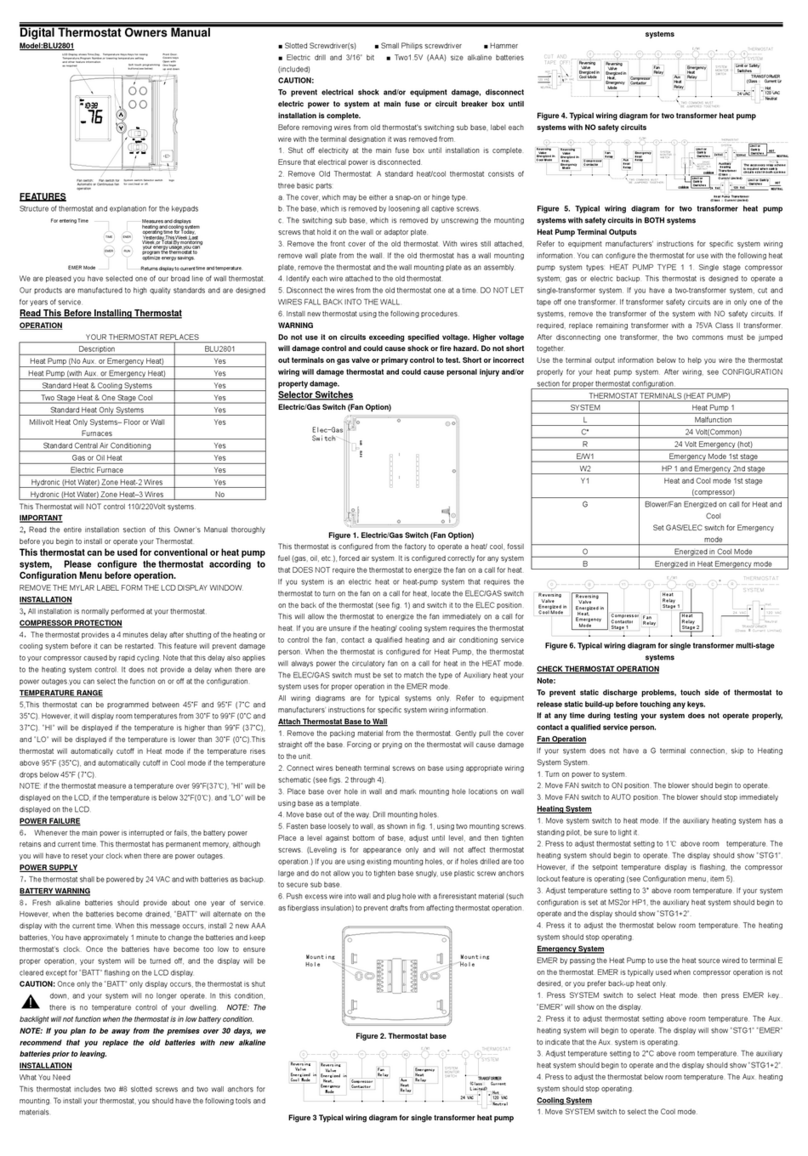
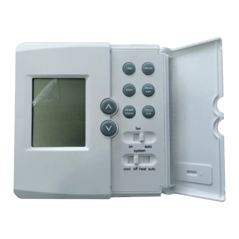
Comfort Stat CP1717 User manual

DigitalThermostat
OwnersManual
Mode:CP1717
Yournewthermostatwillprovideyearsofreliableservice.Usingthis digitalthermostatwillprovidemoreuniformcomfortinyourhomethrough
theseasons.Thankyouforbuyingtheproduct!
Pleasereadthismanualforcompleteinstructionsoninstallingandoperatingyourthermostat.Ifyourequirefurtherassistance,pleasefeelfreetocontactus.
IMPORTANTINFORMATION
1.Thisthermostatisdesignedtoworkonthefollowingsystems:
ŸGas–StandingPilot ŸOil–FiredFurnace
ŸGas–ElectronicIgnition ŸSingleStageHeatPumps–withno
ŸGas–FiredBoilers auxiliaryheat
ŸGas–MilivoltSystems ŸElectricFurnace
ŸOil–FiredBoilers ŸElectricAirConditioning
ThisthermostatwillNOTcontrolmultistageheatpumpsor110/220Vbaseboardelectricheatingsystems.
2.TemperatureRange
Thisthermostatcanbesetbetween45˚Fand95˚F(7˚Cand35˚C).However,itwilldisplayroomtemperaturesfrom30˚Fto99˚F(0˚Cand37˚C).“HI”willbedisplayed
ifthetemperatureishigherthan99˚F(37˚C),and“LO”willbedisplayedifthetemperatureislowerthan30˚F(0˚C).
ThisthermostatwillautomaticallycutoffinHeatmodeifthetemperaturerisesabove95˚F(35˚C),andautomaticallycutoffinCoolmodeifthetemperaturedropsbelow
45˚F(7˚C).
3.CompressorProtection
Thisthermostatprovidesa4minutedelayaftershuttingoffthecompressorbeforeitcanberestarted.Thisfeaturewillpreventdamagetoyourcompressorcausedby
rapidcycling.Itdoesnotpreventarapidcompressorrestartduetoshortpoweroutages.
4.BatteryWarning
TwofreshAAalkalinebatteriesshouldprovidewelloveroneyearofservice.However,whenthebatteriesbecomedrainedtheLowBatteryIndicatorwillflashonthe
display.Whenthismessageoccurs,installnewalkalinebatteries.Youhaveapproximately1minutetochangethebatteriesandkeepthethermostat’ssettings.Once
thebatterieshavebecometoolowtoensureproperoperation,yoursystemwillbeturnedoff,andthedisplaywillbeclearedexceptforflashingLowBatteryIndicator
ontheLCDdisplay.
CAUTION:When only the battery icon flashes on the display, the thermostat is shut down, and your system will no longer operate. In this condition, there is no
temperaturecontrolofyourdwelling.
NOTE:Thebacklightwillnotfunctionwhenthethermostatisinlowbatterycondition.
NOTE:Ifyouplantobeawayfromthepremisesover30days,werecommendthatyoureplacetheoldbatterieswithnewalkalinebatteriespriortoleaving.
FEATURES
Structureofthermostatandexplanationforthekeypads

heat
off
cool
system
on auto
fan
OPERATION
Startup
The LCD will show the factory default displayof70˚F(21˚C)whenbatteriesarefirstinstalled,.Thetemperaturewillupdate
afterafewseconds.
SystemSelectorSwitch
TheSystemSelectorswitchonthefrontofthethermostatdeterminestheoperatingmodeofthethermostat.YoumayselectCOOL,OFF,HEAT.
NOTE:Anytimeyouinstallorremovethethermostatfromthewallplate,slidetheSystemSelectortotheOFFpositiontopreventthepossibilityofa
rapidsystemOn–OFF.
FanSwitch
TheFanswitchshouldnormallybelocatedintheAUTOposition.TheFanwillbeturnedonalongwithnormaloperationofyoursystem.Inanormal
gasoroilfurnace,theFanwillbeturnedonbyyourfurnaceafteritswarmupdelay.Forelectricheat,airconditioning,andheatpumpoperation,the
Fanwillturnonwiththesystem.
ToruntheFanoncontinuously,slidetheFanswitchtotheONposition.
ReviewCurrentSetTemperature
ŸPresseithertheupordownkeyoncetoseetheSetTemperature.
Thefactorydefaultis68˚F(20˚C)whenstartedwiththeSystemSwitchOfforHeat,and78˚F(26˚C)whenstartedwiththeSystemSwitchonCool.
SettingNewTemperature
Ÿ Press either the up or down once and displaythesettemperature.
ŸPresseitherupordownagaintochange toyourdesiredSetTemperature.Holdthekeydownforover2secondstofast advance
theSetTemperature.
Thedisplaywillreturntothenormalroom temperatureafterthekeyshavebeenreleasedfor5seconds.
FilterMonitor
Thethermostatcountsthenumberofhours yoursystem’sfilterhasbeeninuse.Tomaximizeyoursystem’sperformanceand
energy efficiency, change or clean your filterregularly.W henthetotalsystemruntimeforheatandcoolreaches400hours,the
Filter Change Indicator will flash as a remindertocheckyoursystem’sfilter.
Afterchangingorcleaningthesystemfilter, pressandholdtheFilterkeyfor3seconds.The displaywillblink,andthecounterwill
beresettozero.
Note:PressingtheFilterkeyatanytimeforlessthan3secondswillcausetheFilterChangeIndicatortoappearontheLCD.Thisisonlytoconfirmkeyoperation,and
thecounterisnotaffectedunlessthekeyisheldforgreaterthan3seconds.
SPANSetting
Yourthermostatissetatthefactorytocycleat2˚F(1˚C)aboveandbelowthe settemperature.(Span=2)Thissettinghasbeendesignedtoprovide acomfortable
roomtemperatureundermostallconditions.However,ifyoufindyoursystemcyclingtoofastortooslow,thentheSpancanbeadjustedtomodifythecycletime.
ŸPressandholdBOTHupanddownkeysforthreeseconds.SPANwillbedisplayedontheLCD.
ŸPressuptoraisetheSpanto3.ThissettingINCREASEStocycletimebyallowingyoursystemtorunLONGER.
ŸPressdowntolowertheSpanto1.ThissettingDECREASESthecycletimebycausingyoursystemtorunSHORTER.
TheSpansettingsremainthesameforbothHEATandCOOL,andcanbechangedinanySystemSwitchposition.
COO L OF F HE AT ON A U TO
SY ST E M FAN
FilterChange
Indicator:Flashes
whenfilterneeds
tobechecked.
LCDDisplay:
ShowsRoom
Temperature,Set
Temperature,and
otherfeature
informationas
required.
Light:Backlight
display
automatically
witheachkey
pressforeasy
viewing.
LowBattery
Indicator:
Flasheswhen
batteriesneed
tobereplaced.
FrontDoor:
Batterycover
Openwithone
fingerfromtop.
System
Switch:
Selector
switchfor
Heat,Cool,
andOff.
FanSwitch:
Fanswitch
forAutomatic
orContinuous
fanoperation.
FilterKey:
Resetsthe
filterchange
countertozero.
UpandDownKeys:
Keysforchanging
theTemperature
setting.Alsoused
foradjustingthe
Span.
Battery
Compartment:
Frontaccessallows
easyinsertionof
twoAA1.5V
batteries.
FrontDoor:
CoverkeysOpenwith
onefingerfromleftorright.

Whenbatteriesareinstalledinthethermostat,theSpanisresetbacktosetting2.
Backlighting
Yourthermostathasanelectroluminescentlampthatbacklightsthedisplayforeasyviewinginthedark.
Whenanykeyispressed,thedisplayisilluminated.
Thedisplaywillremainilluminatedfor7secondsafterthelastkeyispressed.Thisallowsthelighttostayonifyouneedtooperateseveralkeys.
Note:IfthethermostatisinLowBatterywarningcondition,thebacklightwillnotoperate.Replacewith2newAAalkalinebatteriestorestorethe
Backlightfunction.
LowBatteryWarning
Your thermostat has a twostage lower battery warning system. When the batteries are first detected to be weak, the first stage low
battery warning is indicated by battery symbol flashing on the LCD display. At your earliest convenience, you need to replace the
batterieswith2newAAalkalinebatteries.When thebatteriesbecometooweekfornormal operation,thethermostatentersthesecond
stagelowbatterywarningwhichshutsdownthe thermostat. In this condition, battery symbol flashes alone on the display, and the
thermostatwillturnyoursystemoff.Yoursystem willremainshutoffuntilthebatteriesarereplaced.
Note:ThethermostatwillstillkeepthecurrentSetTemperatureandFilterruntimeinmemoryuntilnewbatteriesareinstalled.Afterconfirmingthatnewbatterieshave
beeninserted,thethermostatwillreturntonormaloperating.
ErrorMode
Ifthethermostatisunabletocontrolyoursystemduetoanunexpectedbatteryproblem,thethermostatwillenterErrorMode.Inthiscondition,thethermostatflashes
“E1”or“E2”ontheLCDdisplay,andshutsoff yoursystem.
To correct this problem, replace thebatteries with2 newAA alkaline batteries, evenif you have recently replaced them. Next, Move
the battery out hold any key then place the batteryagain.Youwillneedtoreprogramyourthermostatandconfirmnormaloperation.
If Error Mode returns, please call us for furtherinformation.
AutoCutOff
Your thermostat will automatically cutoff in Heatmodeiftheroomtemperaturerisesabove95˚F(35˚C).ItwillcutoffinCoolmodeif
the room temperature drops below 45˚F (7˚C).
Note that if your system has malfunctioned andnolongerrespondstothermostatcontrols,theAutoCutOffwillhavenoeffect.
MechanicalHeatBackup
ThisthermostatincludesabimetalswitchthatwillautomaticallyturnontheHeatwhenthetemperaturereachesabout41˚F(5˚C).WARNING:Thisswitchonlyactivates
theHeatingterminal(W).ThesystemitselfmustbecapableofautomaticallyturningtheFanOn.WithoutnormalFanoperation,severedamagetotheheatingsystem
couldresult.
INSTALLATION
WhatYouNeed
Thisthermostatincludestwo#8slottedscrewsandtwowallanchorsformounting.Toinstallyourthermostat,youshouldhavethefollowingtoolsandmaterials.
ŸSlottedScrewdriver(s)
ŸSmallPhilipsscrewdriver
ŸHammer
ŸElectricdrilland3/16”bit
ŸTwo1.5V(AA)sizealkalinebatteries(included)
RemoveOldThermostat
CAUTION:Donotremoveanywiringfromexistingthermostatbeforereadingtheinstructionscarefully.Wiresmustbelabeledpriortoremoval.
INPORTANT!Turnoffthepowertothefurnaceatthemainpowerpaneloratthefurnace.
Remove existingthermostatcover andthermostat.Somethermostatswill have screws or other lockingdevices that mustfirstbe removed. Once thewall mounting
plateisexposed,lookforwires.Ifwiresarenotvisible,theymaybeconnectedtothebackofthewallplate.Again,lookforscrews,tabs,etc.Somemodelshavedoors
thatopentoexposewiresandmountingscrews.SeeFigure1.
TypicalHomeThermostats
WallmountingPlateThermostatCover

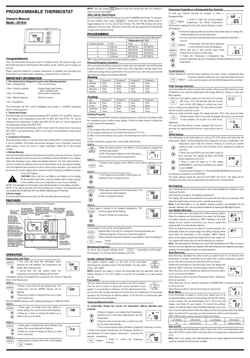
Figure1
WiringLabeling
ŸEachwirecomingfromthewalltotheexistingthermostatisconnectedtoaterminalpointonthatthermostat.Eachoftheseterminalpointsisusuallymarkedwitha
codelatterasshowninTableAbelow.
ŸNotethatthisthermostathasmultiple functionterminalsthat allowSingleStageHeatPumpcapability.Standardsystemsuse:Rh,Rc,G,Y,W.[SingleStageHeat
Pumpsuse:R,Y,G,andOorB.]TableAbelowshows
themultiplefunctionsoftheterminals.Usetheterminalsthatmatchyoursystem.
ŸThenumberofwiresinyoursystemcanbeasfewastwo(forheatonlysystems),asmanyaseight,oranynumberinbetween.Ifyoufollowthelabelingprocedures
correctly,youdonothavetobeconcernedabouthowmanywiresthereare.
ŸThereisoftennoterminalmarking onthe existingthermostatoftwowire,heat only systems.Justconnecteitherofthewirestothe RHterminal,thenconnectthe
otherwiretotheWterminaltocompletethecircuit.
ŸIMPORTANT!BEFOREDISCONNECTINGANYWIRES,APPLYTHESELFADHESIVELABELSPROVIDEDTOTHEWIREASSHOWNINTABLEABELOW.(For
example,attachthelabelmarkedWtothewirethattoestotheWorHterminalonyourexistingthermostat.)IGNORETHECOLOROFTHEWIRESsincethesedo
notalwayscomplywiththestandard.
ŸAfterlabelingwires,disconnectthemfromtheexistingthermostat.
ŸRemoveexistingwallplate.Tomakesurewiresdonotfallbackintowallopening,youmaywanttotapethemtothewall.
ŸIfholeinwallislargerthannecessary forwires,sealthisholewithinsulatingmaterialsothatnohotorcoldaircanenterthebackofthethermostatfromthewall.
Thisaircouldcauseafalsethermostatreading.
TableA
Ifthecodeletteron
yourexisting
Thermostatis
thenmarkthewire
withlabelshown
andconnectto
thermostatterminal
shown
NOTE:Donotconnecta“Common”wire(sometimes
labeled“C”)toanyterminalonthisthermostat.Tapeupthewireanddonotuse.Thiswireprovideselectricitytononbattery
poweredthermostats.
MountwallplateandThermostat
ŸRemovethewallplatefromyourthermostatbypressingthereleasetabonthebottomofthethermostat.SeeFigure2.
RH,R,VRor4
24Volt
or
B
ReversingValveoperatinginHeatmode.
(SingleStageHeatPumpsONLY.)
ReversingValveoperatinginCoolmode.
(SingleStageHeatPumpsONLY.)
or
O
24VoltCool
RC,VC
GorF
Fan
Y,Y1,CorM
AirConditioningCompressor
or
SingleStageHeatPump
Compressor
WorH
Heating
R
24Volt
(SingleStageHeatPumpsONLY.)
Rh/B
W
R
Y
G
Rc/O
Rh/B
Rc/O
G
Y
W
R

Figure2
ŸPositionwallplateonwallandpullexistingwiresthroughlargeopening.Thenlevelforappearance.Markholesforplasticanchorsprovided,ifyourexistingholesdo
notlineupwiththoseonthewallplate.
ŸDrillholeswith3/16”bitandgentlytapanchorsintotheholesuntilflushwithwall.
ŸRepositionwallplatetowall,pullingwiresthroughlargeopening.Insertmountingscrewsprovidedintowallanchorandtighten.SeeFigure3.
Figure3
NOTE:5WireSystems
IfyourthermostathasonewiremarkedRorRh(2,3,or4wiresystem),thenleavethejumperwirebetweentheRhandRcterminalsonthewallplate.Otherwise,if
youhaveseparateRhandRcwires(5wiresystem),thenremovethejumperwirebetweentheRhandRcterminals.
ConnectWiresandMountThermostattowallplate
ŸMatchandconnectthelabeledwirestotheappropriatecodedterminalscrewsonthewallplate.(SeeFigure4,5.)Ignoreanywireswhichmaybepresent,butwhich
werenoteconnectedtotheoldthermostat.
Figure4Figure5
ŸRefertotheWiringDiagramsbelowtobesureyoursystemiswiredcorrectly.
ŸIfyoursystemisasinglestageheatpumpandusesanOorBwire,youmustmovetheSystemSelectorswitchinsidethethermostattotheHeatPumpposition.If
youhaveanormalfurnaceorelectricsystem,leavetheswitchintheStandardposition.RefertotheSystemSelectorsectiononthebackformoreinformationonthis
switch.
ŸBesuretotightentheterminalscrewssecurely,otherwisealoosewirecouldcauseoperationalproblemswithyoursystemorthermostat.
ŸPushexcesswirebackintotheholetopreventinterferencewheninstallingthethermostattothewallplate.
ŸMakesuretheSystemSwitchissettoOFF,andtheFanSwitchissettoAUTO.
R
Rh/O
G
Y
W
Rc/B

ŸInsertthetabs ontopofthethermostatbodyintotheslots atthetopofthewallplate.Pressthebottomofthethermostatbodyintothesnaponthe bottom ofthe
wallplate.RefertoFigure2.(NOTE:Donotforcethethermostatontothewallplate,astheterminalpinsmaybedamaged.Ifitdoesnotsnapproperly,thethermostat
maynotwork.)
ŸInsertthetwoAAsizealkalinebatteries,observingthepolaritymarkedinsidethebatterycompartment.
ŸSwitchonthemainpoweratthepanelorfurnace.
WiringDiagrams
XNoConnection
SelectorSwitches
Inorderforthisthermostattocontrolyoursystem,thesystemtypemustbespecifiedbytheselectorswitchesontheprintedcircuitboardinsidethethermostat.There
isalsoaselectorswitchforyourchoiceofFahrenheitorCelsiustemperaturedisplay.Seefigure6.
ŸHeatingSystemSelector(HG–HEswitch)
Thefactorypositionforthisswitchisinthe“HG”position.Leaveitinthispositionifyouhaveagasfurnaceoranoilburner.Ifyouhaveanelectricfurnace,testtosee
whethertheHeat andFancomeon as expectedafterinstallation.IftheFanoperationisnormal,leaveitinthe“HG”position.IftheFandoesnotcome onwithin a
minuteofthethermostatcallingforheating,changetheswitchpositionto“HE”.Thesystemselectorhasnoeffectinthecoolingmode.
NOTE:“HG”positionisforgasandmostothersystems.“HE”positionisforcertainelectricsystemshavingafanrelay.
ŸSystemSelector(STANDARD–HEATPUMPswitch)
R G W Y Rh/B Rc/O
Wallplate
Terminals
Jumper
Fan
Relay
HeatRelay
orValve
Cool
Contactor
Heat/Cool
24VSupply
System
Selector
STD
HP
Fan
Relay
Reversing
Valve
Compressor
Contactor
Wallplate
Terminals
R G W Y Rh/B Rc/O
System
Selector HP
STD
Fan
Relay
R
Wallplate
Terminals
Heat24V
Supply
Cool
Contactor
HeatRelay
orValve
Coo l24V
Supply
NoJumper
W
G Rh/B
Y Rc/O
System
Selector HP
STD
Jumper
24V
Supply
Heat
Mode
Cool
Mode
OR
Heat24Vor
MillivoltSupply
HeatRelay
orValve
Wallplate
Terminals
R
Jumper
G W Y Rh/B Rc/O
System
Selector HP
STD
Wallplate
Terminals
R
System
Selector
Heat24V
Supply
HeatRelay
orValve
G W Y Rh/B Rc/O
Jumper
HP
STD
Fan
Relay
Fan
Relay
Wallplate
Terminals
R
Cool
Contactor
Cool24V
Supply
G W Y Rh/B Rc/O
System
Selector HP
STDJumper
4WireHeat/CoolSystem
5Wire/HeatCoolSystem
SingleStageHeatPumpSystem
2WireHeatOnlySystem
3WireHeatOnlySystem
3WireCoolOnlySystem
Connect to proper Reversing
ValveTerminals.SeeTableA

ThefactorypositionforthisswitchisintheSTDposition.LeaveitinthispositionifyouhaveANYsystemthatusesgas,oil,electric,orhotwaterheating.Ifyouhavea
singlestageHeatPump(noauxiliaryoremergencyheatsource),thenslidetheswitchtotheHPposition.Besurethereversingvalvewireisconnectedtothecorrect
terminalforyourheatpump(Rc/O)or(Rh/B).
ŸF˚/C˚selector(Fahrenheit/Celsius)
YourthermostatissetforF˚modefromthefactory.InordertochangetoC˚mode,slidetheswitchtoC˚andholdanykeyabout2secondswithoutthebattery,then
placethebatteryagain.
NOTE:Unlesspressanykeyabout2secondswithoutthebattery,thenplacethebatteryagain.
Figure6
TROUBLESHOOTING
Problem Solution
1.Checkbatteryconnectionsandbatteries.NoDisplay
2. Move the battery out and wait for about 1
minutesthenReplaceBatteries..
Entire Display
Dims.
1.ReplaceBatteries.
AutoFanDoesNot
TurnOnProperly.
1.MoveHG/HEselectortocorrectposition.
1.Checkthatthefunctionswitchisinthecorrect
position(“HEAT”or“COOL”).
2. There may be as much as 4mintue delay
beforethe system turns On –wait and check.
(Compressorprotectiondelay.)
3. Check your circuit breakers and switches to
ensurethereispowertothesystem.
4.Replacebatteries.
5.Makesureyourfurnaceblowerdoorisclosed
properly.
6. If your nonheat pump system only uses 4
wires, be sure the jumper wire is installed
betweentheRh/BandRc/Oterminals.
7. Check the position of the Reversing Valve
selectorswitch:StandardorHeatPump.
Heating or Cooling
DoesNotGoOnor
Off.
8. If you have singlestage heat pump, be sure
thejumperwireisinstalledbetweentheYand
Wterminals.
ErraticDisplay 1.Movethebatteryoutholdanykeythenplace
thebatteryagain.Thenreprogram.
Ifunitcontinuesto
operateintheOff
position.
1.Replaceunit.
Thermostat
permanentlyreads
“HI”,“LO”,or“Er”.
1.Replaceunit.
1 2 3 4
Te mp era tur e
Di spla y
Sy st em
Se lecto r
ST D H P
F an Opt ion
HG
HE
K3
JP 2
FA HR EN HE IT C EN TIG RAD E
K5

Table of contents
Other Comfort Stat Thermostat manuals

Comfort Stat
Comfort Stat CP1819 User manual

Comfort Stat
Comfort Stat CP1919 User manual

Comfort Stat
Comfort Stat BLU2801 User manual

Comfort Stat
Comfort Stat CP1818 User manual

Comfort Stat
Comfort Stat BLU1719 User manual

Comfort Stat
Comfort Stat TOUCH ME 1 User manual

Comfort Stat
Comfort Stat BLU2810 User manual

Comfort Stat
Comfort Stat BLU2810 User manual

Comfort Stat
Comfort Stat CP2020 User manual

Comfort Stat
Comfort Stat CP2815 User manual