Inside
Tu
Day
Upstairs
Auto
Downstairs
Airflow %
HEAT
Schedule
AUTO
FANMENU MODE
Heat
Set To
SYSTEM
AM
365
Comfort
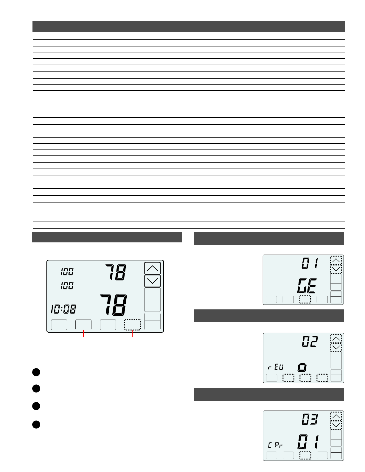
UP/DOWN Keys.
SYSTEM MODE Key
OFF, HEAT, COOL or AUTO
Displays the downstairs
(Inside) or upstairs (Inside2)
temperature.
Displays the Thermostat Mode
HOLD, SCHEDULE or VACANT
Displays the time, day and schedule
MORNING, DAYTIME, EVENING
or NIGHT
MENU Key Displays
the User options.
MODE Key Selects
Thermostat Mode
HOLD, SCHEDULE or VACANT
Displays the upstairs airflow
Displays the Airflow Mode
AUTOMATIC or MANUAL
Displays the heating or
cooling temperature
FAN MODE Key
AUTO or ON
Warranty
This thermostat is warranted to be free of defects due to
workmanship or materials under normal use and service for a
period of 5 years from date of installation and not longer than
6 years from manufacturing date code.
Installer Manual
Model C365T21 and C365T21WF
365
Comfort
eControls, Inc. 26072 Merit Circle #110 / Laguna Hills, CA 92653
949-916-0945 Fax 949-458-8502 www.eControlsUSA.com
eControlseControls
Ver1.8 / Ver2.2_1.0.4 Aug 2017
Displays the downstairs airflow
NEXT Key
Used to advance through
options
ENTER Key
Used to save options and
return to thermostat operation
i
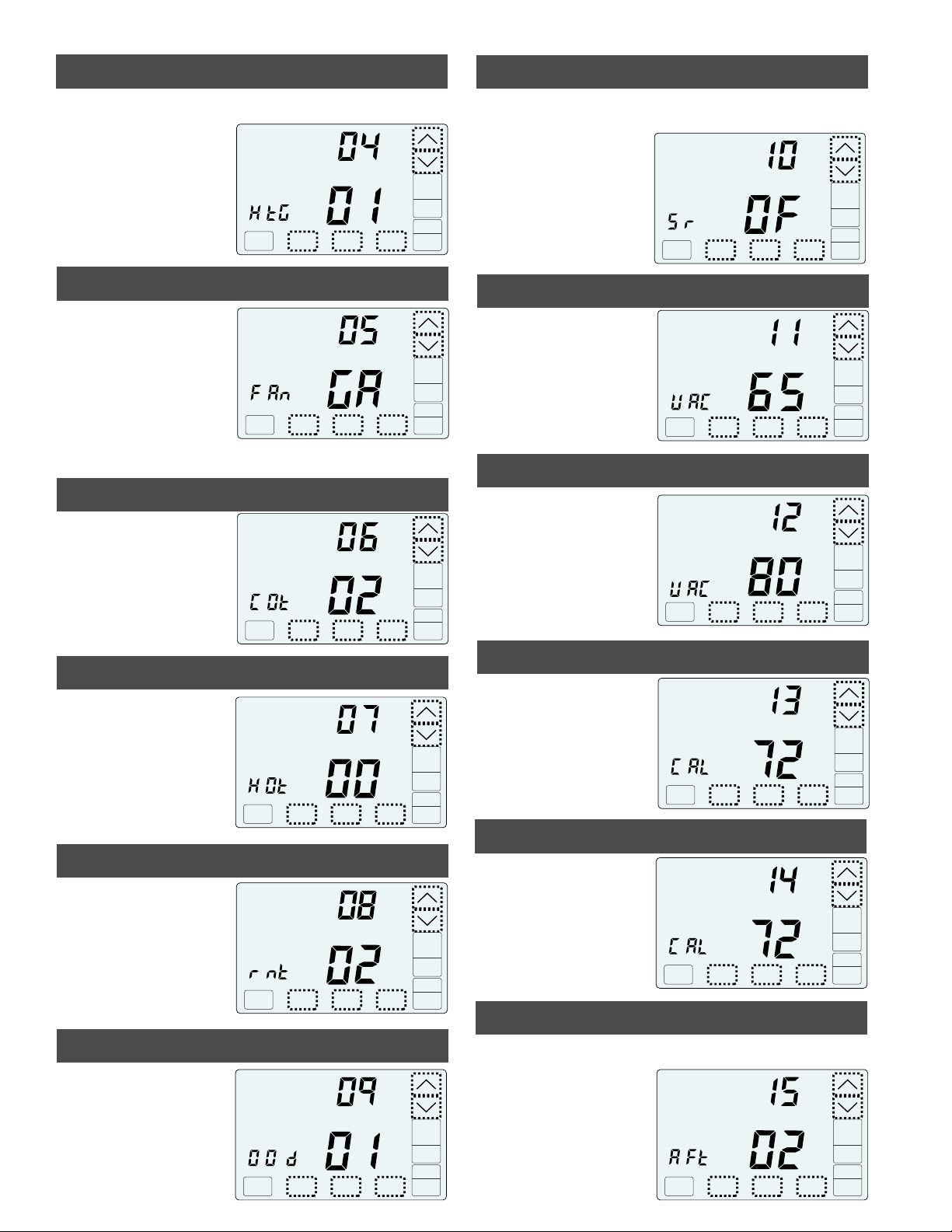
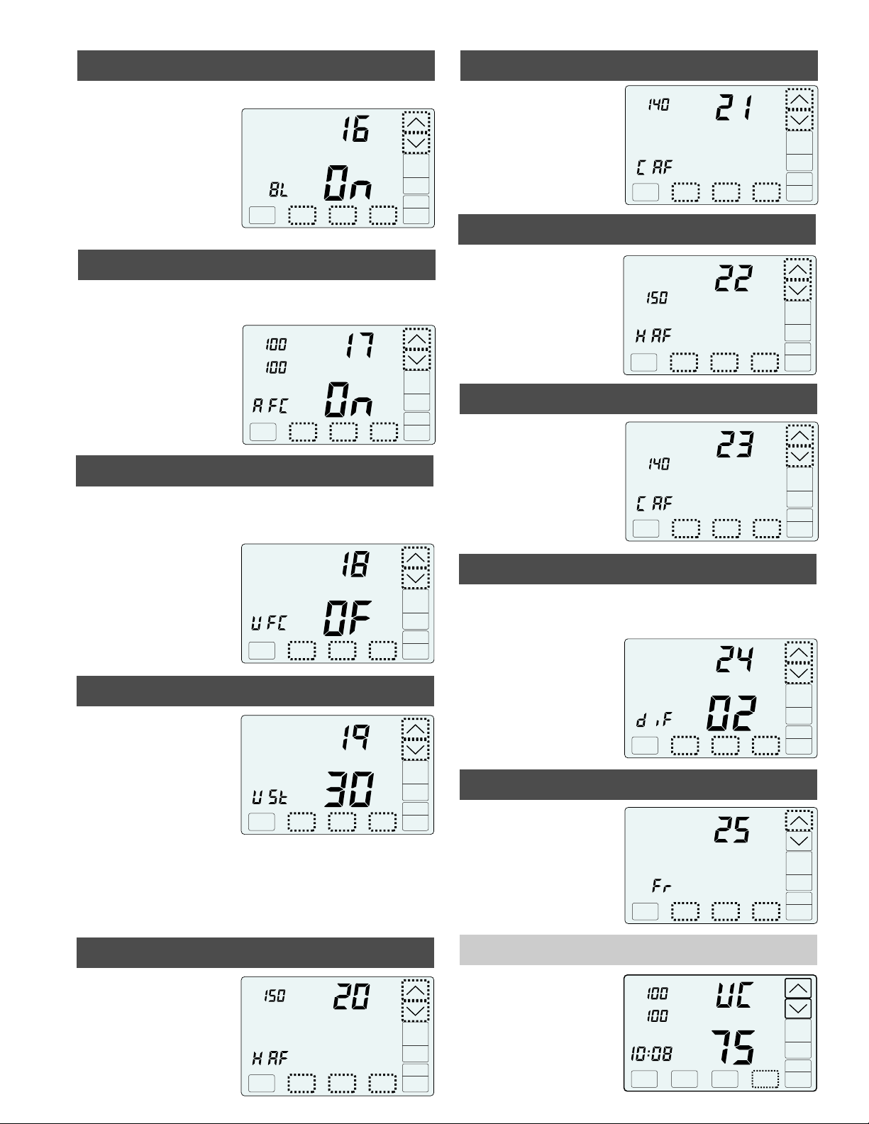
To disable airflow control so the thermostat operates
as a typical thermostat, use Option 17 to turn airflow
control off. The thermostat will control the system as
any other thermostat and the nighttime airflow option
will be disabled.
i
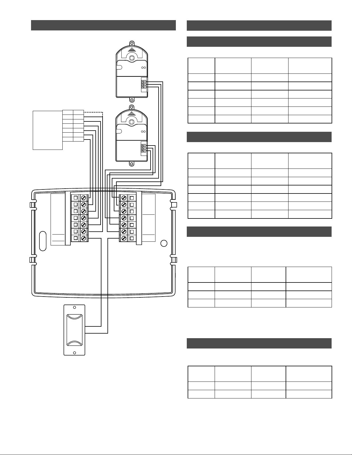
The C365 thermostat controls heating, cooling and airflow to
the upstairs and downstairs using an upstairs and a downstairs
modulating damper. A temperature sensor located upstairs
monitors the upstairs temperature and the temperature sensor
in the C365 monitors the downstairs temperature.
The C365 adjusts the upstairs and downstairs airflow during
heating and cooling calls to maintain uniform upstairs and
downstairs temperatures.
SYSTEM MODES Off, Heat, Cool, Auto
THERMOSTAT MODES Hold, Schedule or Vacant mode.
PROGRAMS PER DAY Morning, Daytime, Evening and Night.
PROGRAM FORMAT Weekdays and weekend– 5/2.
TEMPERATURE OVERRIDE Temperature is held for 4 hours
when adjusted in Schedule mode.
FAN MODES Auto or Continuous
AIRFLOW CONTROL Airflow can be turned off using Option
15. Dampers fully open, nighttime airflow options are disabled
and airflow is no longer displayed on the thermostat.
AIRFLOW LIMITS Maximum upstairs and downstairs, heating
and cooling airflow limits can be set during installation.
NIGHTTIME OPERATION The C365 thermostat uses the
upstairs temperature sensor to control heating and cooling
calls and directs more airflow upstairs. If bedrooms are located
downstairs, the Nighttime Airflow option should be turned off.
COMPATIBLE EQUIPMENT Gas/electric equipment with 2-
stage heating and 1 stage cooling or 1 stage heating and 2-
stage cooling and heat pumps with 2-stage heating and 2-
stage cooling.
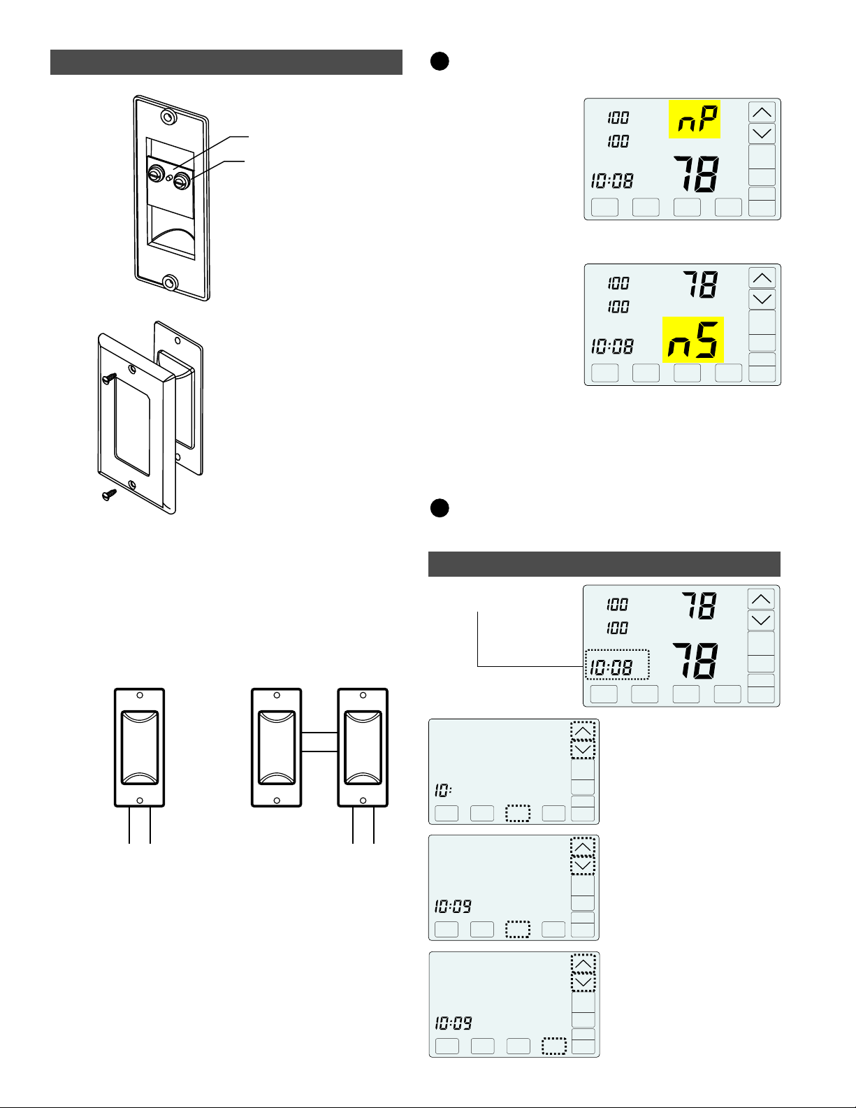
UPSTAIRS TEMPERATURE SENSOR One TS510W sensor
or two TS520W upstairs temperature sensors can be used.
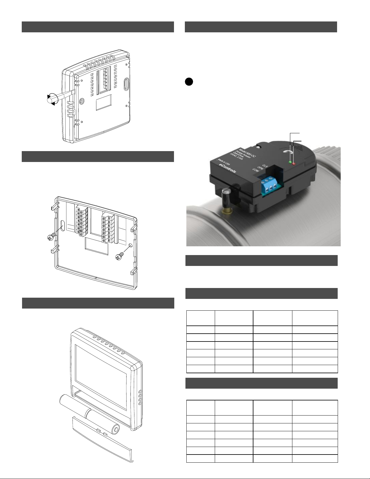
MODULATING DAMPERS Round or rectangular dampers
using the A80MT actuator and up to 1 inch static pressure.
POWER Operates on 24VAC from the HVAC equipment using
the R and C wires.
ATTENTION INSTALLER
i
Nighttime Airflow Option. If bedrooms are located
downstairs, the Nighttime Airflow Option should be
turned OFF using the User Options.
i
Set Options (p.5-7). Options 1 through 5 determine the
equipment operation and must be set if different than
Factory Settings.
After installing and wiring dampers and sensors to the
thermostat, CHECK FOR ERROR MESSAGES (p.4)
Set time of day (p.4)
i
Description