8
05-06 Testing Cooling Airflow Limits
In Option 5, the system is Off.
Touch to go to Option 6 to
activate cooling. Verify the
equipment is operating.
To determine the maximum
allowable upstairs airflow, touch
the key until the airflow is too
great and causes noise or
annoyance. Lower the airflow
using the key until it is
acceptable. This is the maximum
allowable upstairs airflow in
cooling. Record the airflow
value.
NEXT
UP
DOWN
This test is used to determine the maximum allowable upstairs airflow
and maximum allowable downstairs airflow in COOLING.
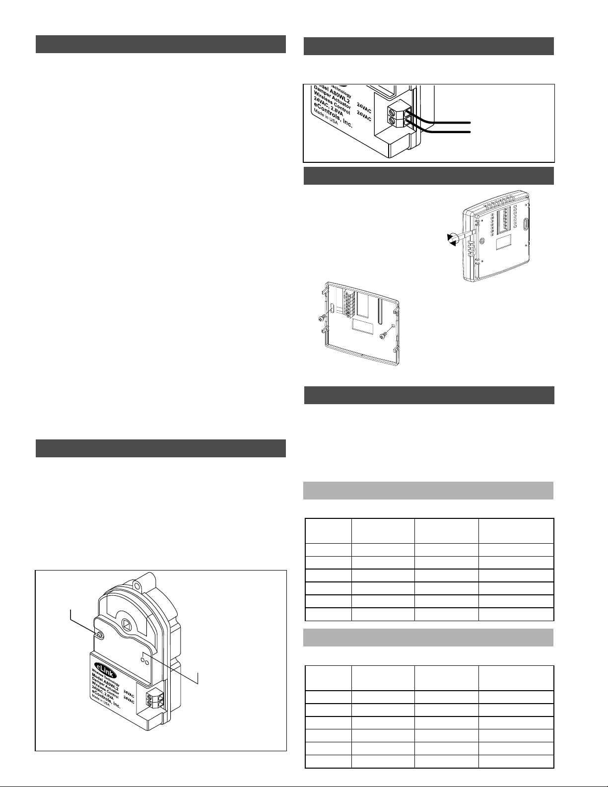
The dampers have a red and a green LED indicator that indicate the
position and status of the damper.
Green LED On Continuously The damper is in the fully open position.
Green and Red LEDs Alternately Blinking The damper is in a
modulated position between fully open and closed.
Green LED On and Red LED Blinking The damper has lost
communication with the C365 Thermostat and gone to the fully open
position until communication is restored.
Upstairs
Downstairs
Airflow %
ENTER
Cool
Upstairs
Downstairs
Airflow %
ENTER
Cool
Maximum Allowable Upstairs Airflow in Cooling
To determine the maximum
allowable downstairs airflow,
touch the key until the
airflow is too great and causes
noise or annoyance. Increase the
airflow using the key until it is
acceptable. This is the maximum
allowable downstairs airflow in
cooling. Record the airflow value.
DOWN
UP
Maximum Allowable Downstairs Airflow in cooling
Touch to end testing and return to normal thermostat
operation.
ENTER
Upstairs
Downstairs
Airflow % Cool
Enter the maximum airflow limits using Options 20
through 23 of the installer menu.
Damper LED Indicators
Test
Test
NEXT
Test
NEXT
The test can also be used to perform the HERS Total Airflow test. The
test activates a cooling call and opens both dampers to 100%.
Upstairs
Downstairs
Airflow %
ENTER
Heat
To determine the maximum
allowable downstairs airflow,
touch the key until the
airflow is too great and causes
noise or annoyance. Increase
the airflow using the key
until it is acceptable. This is the
maximum allowable downstairs
airflow in heating. Record the
airflow value.
DOWN
UP
Maximum Allowable Downstairs Airflow in Heating
Touch to go to Testing Cooling Airflow Limits.NEXT
03-04 Testing Heating Airflow Limits (cont.)
Test
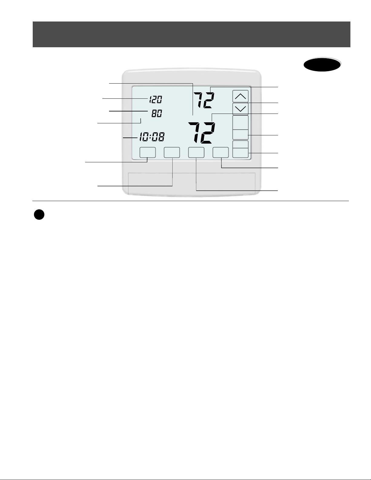
WiFi model only.
When participating in Demand
Side Management with the utility
company, the thermostat will
display UC (Utility Control) when
the utility company has limited
the cooling setpoint setting in the
thermostat.
Demand Side Management
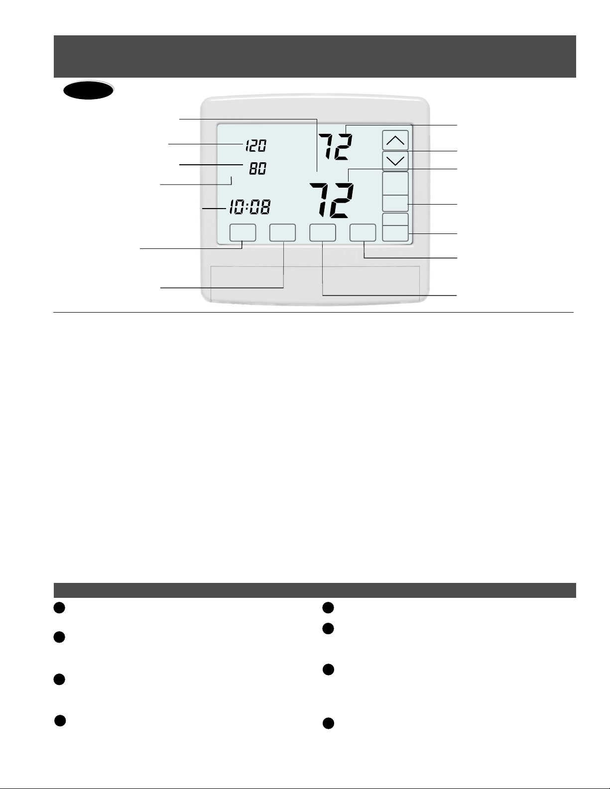
Inside
Tu
Day
Upstairs
Auto
Downstairs
Airflow %
COOL
Schedule
AUTO
FANMENU MODE
Cool
Set To
SYSTEM
AM
Warranty
This thermostat is warranted to be free of defects due to
workmanship or materials under normal use and service for a
period of 5 years from date of installation and not longer than
6 years from manufacturing date code.
eControls, Inc. 26072 Merit Circle #110 / Laguna Hills, CA 92653
949-916-0945 Fax 949-458-8502 www.eControlsUSA.com
eControlseControls
This test is used to verify that the indoor fan is operating correctly.
FAN
FANENTER
01-02 Testing Indoor Fan Operation
NEXT
Test
Test
Upstairs
Downstairs
Airflow %
Upstairs
Downstairs
Airflow %
In Option 1, the Fan is Off.
Touch to go to Option 2
to turn on the indoor fan. Verify
the fan is operating and
delivering airflow to the
upstairs and downstairs..
Touch to go Testing
Heating Airflow Limits.
NEXT
NEXT
This test is used to determine the maximum allowable upstairs airflow
and the maximum allowable downstairs airflow in HEATING.
ENTER
ENTER
Heat
Heat
Maximum Allowable Upstairs Airflow in Heating
03-04 Testing Heating Airflow Limits
NEXT
NEXT
Test
Test
Upstairs
Downstairs
Airflow %
Upstairs
Downstairs
Airflow %
In Option 3, the system is Off.
Touch to go to Option 4
to activate heating. Verify the
equipment is operating.
To determine the maximum
allowable upstairs airflow,
touch the key until the
airflow is too great and causes
noise or annoyance. Lower the
airflow using the key
until it is acceptable. This is the
maximum allowable upstairs
airflow in heating. Record the
airflow value.
NEXT
UP
DOWN
ENTER
NEXT
NEXT
ENTER
NEXT