CTK03 ComfortNet™ Communicating Thermostat
3I/O-CHTSTAT03 69-2688—03
Installation
Thisbookletcontainsinstallationinstructionsandinformationonthethermostat
andwirelessaccessories.Separateinstallationinstructionsforthefurnaceor
airhandlerandoutdoorACcondensingunitorheatpumpareprovidedwiththe
appropriateequipment.Thisthermostatisdesignedexclusivelyforusewiththe
ComfortNetcommunicatingsystem.
Valid System Configurations
Thiscontrolmayonlybeusedwithcertainsystemconfigurations.Validsystem
configurationsforwhichthiscontrolcanbeusedare:
• AcommunicatingairhandlermatchedwithacommunicatingoutdoorAC
condensing unit.
• Acommunicatingairhandlermatchedwithacommunicatingoutdoorheat
pump unit.
• AcommunicatingfurnacematchedwithacommunicatingoutdoorAC
condensing unit.
• Acommunicatingfurnacematchedwithacommunicatingoutdoorheat
pump unit.
• Acommunicatingfurnacematchedwithanon-communicatingsinglestage
ACcondensingunit.
Installing Thermostat
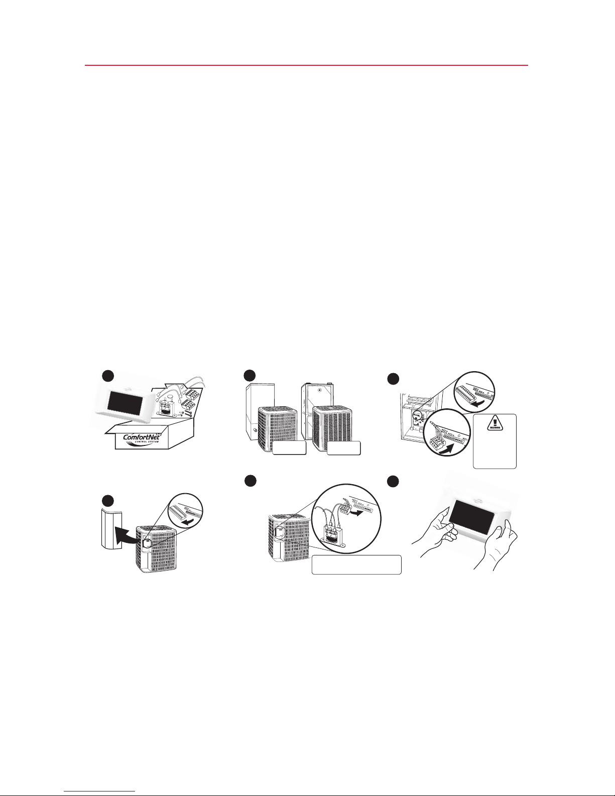
1. RemoveandinventoryallComfortNetcomponents.TheboxcontainstheComfortNetCTK03
communicatingthermostat,lithiumcoincellbattery,wallmountingscrewsandanchors,
systeminstallationguide,operatingmanual,transformerandawiringsetthatincludestwo
terminalblocksandwires.
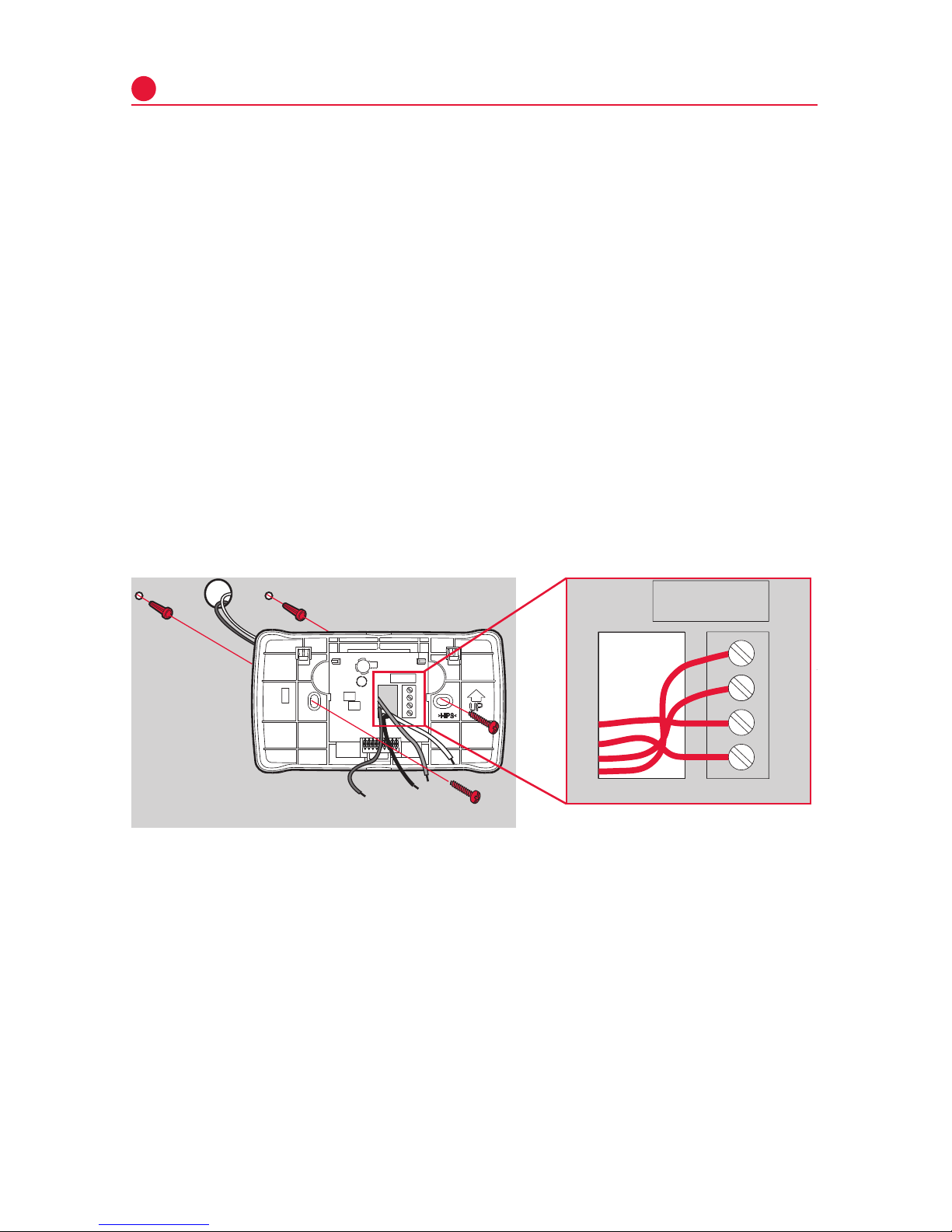
2. Carefullyseparatethethermostatbodyfromthethermostatbase.
3. Placebaseatinstallationlocationandmarkmountingholelocationsonwallusingbaseasa
template.
4. Drill mounting holes.
5. Attachbasefirmlytowallusingtwomountingscrews.Levelingisforappearanceonlyand
willnotaffectthermostatoperation.
6. Connectwirestoterminalblockonbase.
7. 18AWGsolidwireisrecommended.
8. Pushexcesswireintowallandplugholewithafireresistantmaterial(suchasfiberglass
insulation)topreventdraftsfromaffectingthermostatoperation.
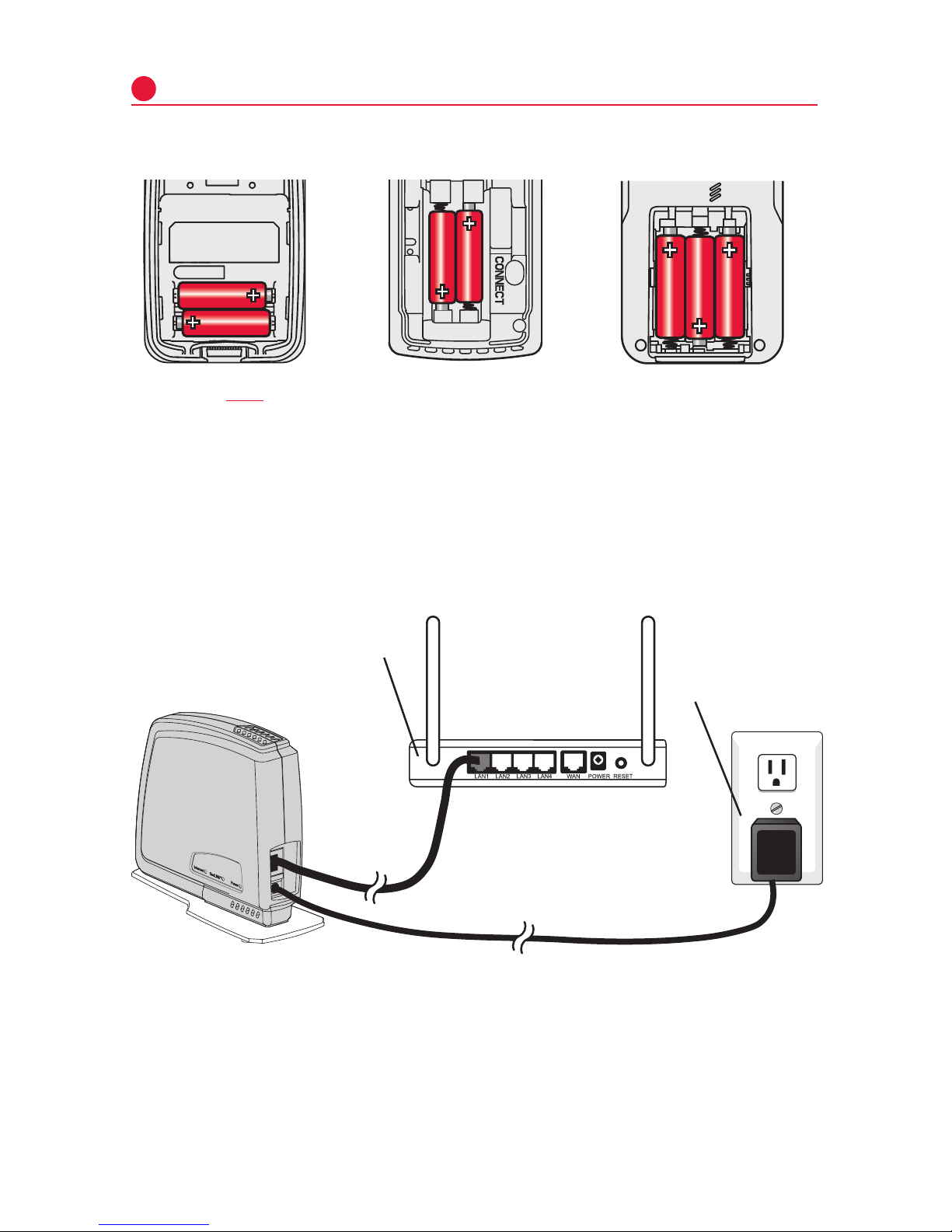
9. Insertcoincellbatteryinthebackofthethermostat.
10. Carefullylineupthethermostatwiththebaseandsnapintoplace.
HIGH
VOLTAGE
TRANSFORMER LOW
VOLTAGE CONNECTED
TO R AND C
TERMINALS
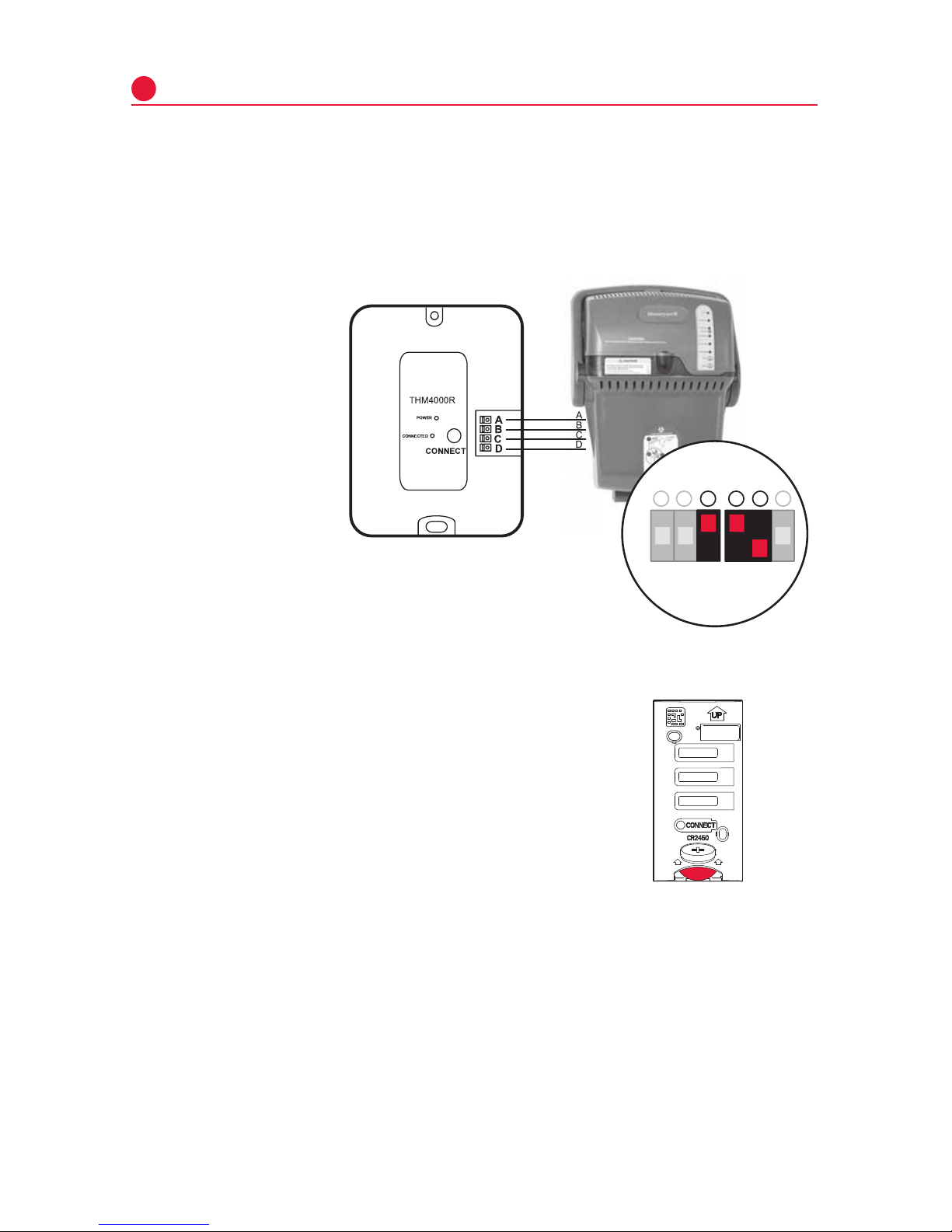
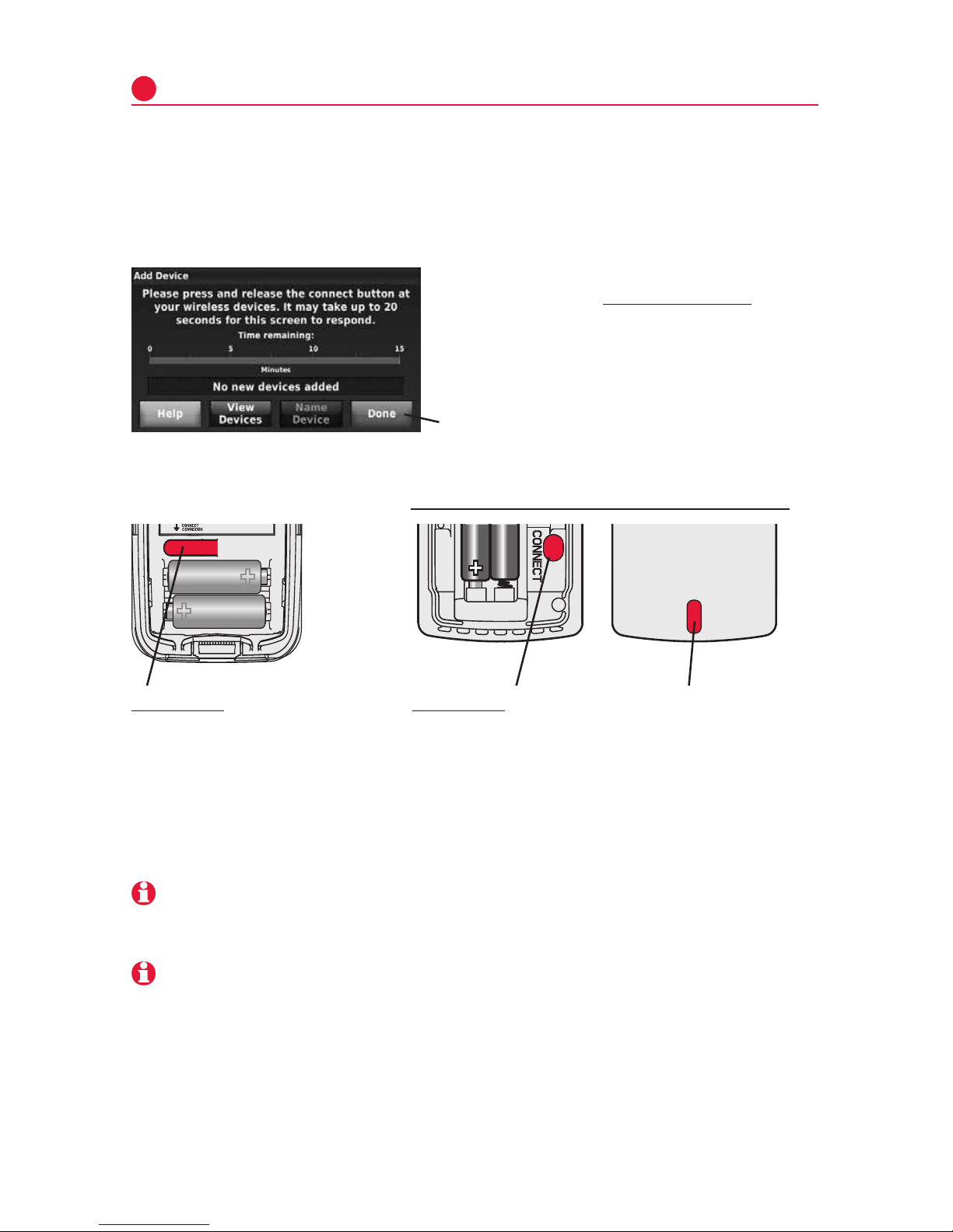
CONNECT 2-WIRES TO
INDOOR UNIT
REMOVE AND INVENTORY ALL
COMFORTNET™COMPONENTS
REMOVE OUTDOOR UNIT
COVER AND 7-PIN
CONNECTOR
NOTE: CONTAINS THE CTK03 THERMOSTAT, LITHIUM COIN CELL BATTERY,
WALL MOUNTING SCREWS AND ANCHORS, SYSTEM INSTALLATION GUIDE,
OPERATING MANUAL, TRANSFORMER AND A WIRING SET THAT INCLUDES
TWO TERMINAL BLOCKS AND WIRES.
P/N F0430675005
INSTALL HVAC COMPONENTS
GAS
FURNACE
AIR
HANDLER
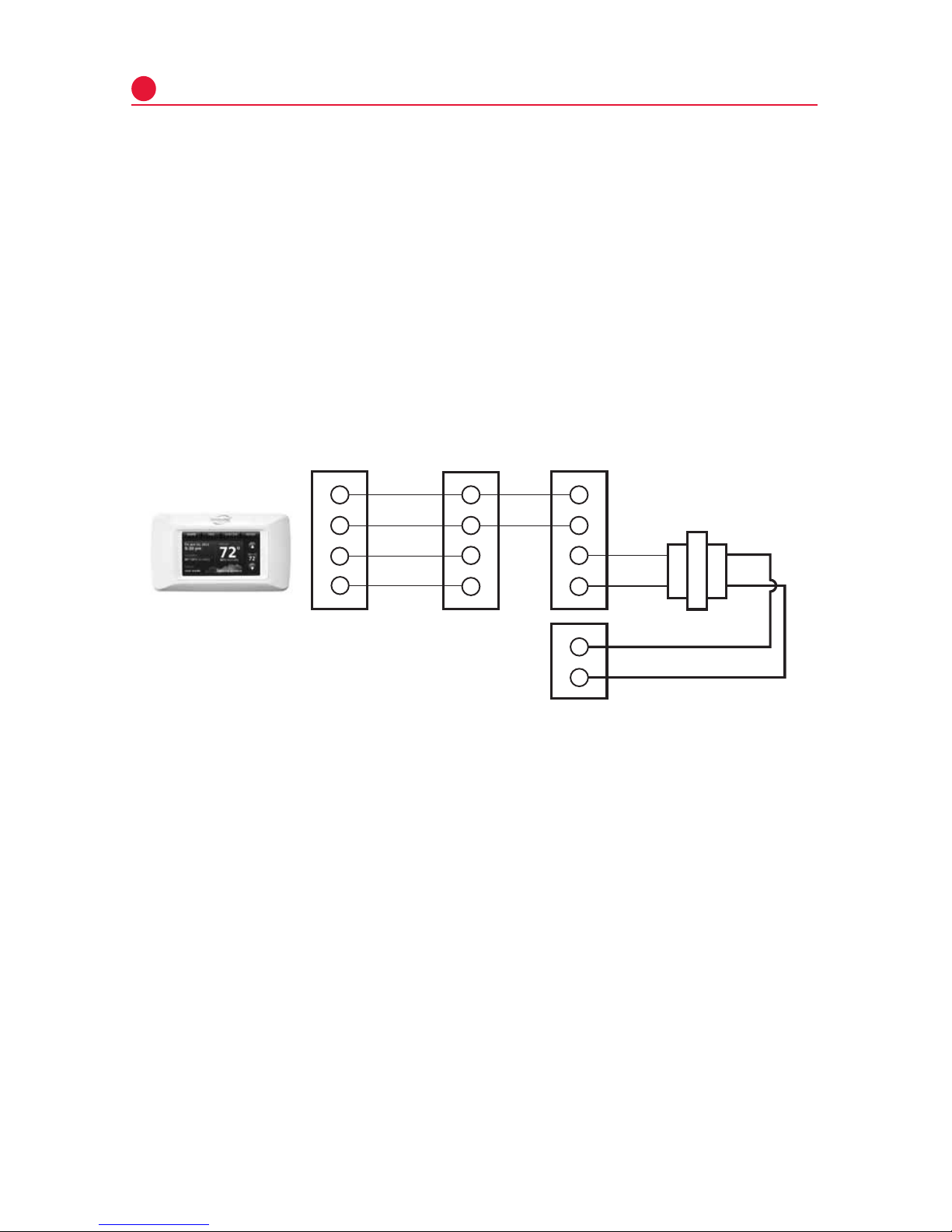
TERMINALS 1 & 2 ARE
COMMUNICATIONS
WIRES. THEY SHOULD
NEVER BE CONNECTED
TO THE 24 VAC R&C
POWER SUPPLY
TERMINALS.
CONNECT 4-WIRES
FROM STAT AND
2 WIRES FROM
OUTDOOR UNIT
P/N F0430679005
P/N F0430673005
CONNECT TO THE OUTDOOR UNIT
2-WIRE/TRANSFORMER
CONNECTION
CONNECT HIGH VOLTAGE TRANSFORMER LEADS TO L1
AND L2 MALE SPADE TERMINALS ON CIRCUIT BOARD.
DO NOT CONNECT R AND C BETWEEN THE INDOOR UNIT
AND OUTDOOR UNIT. SEE PAGE 5.
INSTALL THERMOSTAT ON INTERIOR WALL
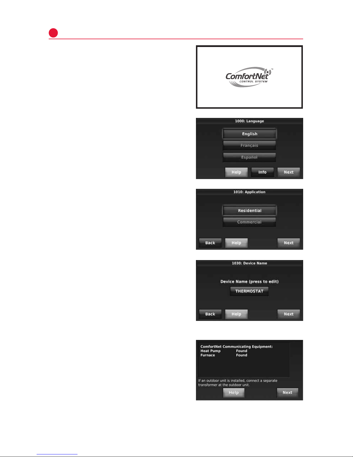
NOTE: THERMOSTAT WILL
AUTOMATICALLY CONFIGURE
TO THE SYSTEM ONCE HIGH
VOLTAGE POWER IS
APPLIED TO THE
INDOOR AND
OUTDOOR
EQUIPMENT.
M33487
1REMOVE 9-PIN CONNECTOR
FROM FURNACE OR AIR
HANDLER CONTROL
23
4
56
AIR CONDITIONER
OR HEAT PUMP
AIR CONDITIONER
OR HEAT PUMP
TRANSFORMER
LOW (24 VAC)
VOLTAGE