Commercial Electric FP2X2/4WY/WH/HDT User manual

THANK YOU
We appreciate the trust and confidence you have placed in Commercial Electric through the purchase of this LED Flat Panel Fixture. We strive
to continually create quality products designed to enhance your home. Visit us online to see our full line of products available for your home
improvement needs. Thank you for choosing Commercial Electric!
USE AND CARE GUIDE
2X2 LED FLAT PANEL FIXTURE
WITH SELECTABLE COLOR TEMPERATURES
Questions, problems, missing parts? Before returning to the store,
call Commercial Electric Customer Service
8 a.m. - 7 p.m., EST, Monday - Friday, 9 a.m. - 6 p.m., EST, Saturday
1-877-527-0313
HOMEDEPOT.COM
SKU# 1003 079 264
Model #FP2X2/4WY/WH/HDT

2
Table of Contents
Table of Contents ...................................2
Safety Information ..................................2
Warranty ..........................................2
Pre-Installation.....................................3
Tools Required ....................................3
Hardware Included.................................3
Installation ......................................4-6
Safety Information
For your safety, always remember to:
□Turn off the power supply at the fuse or circuit breaker box
before you install the fixture.
□Ground the fixture to avoid potential electric shocks and to
ensure reliable starting.
□Double-check all connections to be sure they are
tight and correct.
□Wear rubber soled shoes and work on a sturdy
wooden ladder.
□Account for small parts and destroy packing material, as these
may be hazardous to children.
This fixture is designed for use in a circuit protected by a fuse or
circuit breaker. It is also designed to be installed in accordance with
local electrical codes. If you are unsure about your wiring, consult a
qualified electrician or local electrical inspector, and check your local
electrical code.
WARNING: RISK OF SHOCK. House electric current can
cause painful shock or serious injury unless handled properly.
CAUTION: Turn off the main power at the circuit breaker
before installing the fixture, in order to prevent possible shock.
NOTICE: All electrical connections must be in accordance with local
and National Electrical Code (N.E.C.) standards. If you are unfamiliar
with proper electrical wiring connections obtain the services of a
qualified electrician.
Remove the fixture and the mounting package from the box and make
sure that no parts are missing by referencing the illustrations on the
installation instructions.
FCC STATEMENT
This device complies with part 15 of the FCC Rules. Operation is subject to the following two conditions: (1) This device may not
cause harmful interference, and (2) this device must accept any interference received, including interference that may cause
undesired operation. Note: This equipment has been tested and found to comply with the limits for a Class B digital device,
pursuant to part 15 of the FCC Rules. These limits are designed to provide reasonable protection against harmful interference in
a residential installation. This equipment generates, uses and can radiate radio frequency energy and, if not installed and used
in accordance with the instructions, may cause harmful interference to radio communications. However, there is no guarantee
that interference will not occur in a particular installation. If this equipment does cause harmful interference to radio or television
reception, which can be determined by turning the equipment off and on, the user is encouraged to try to correct the interference
by one or more of the following measures: Reorient or relocate the receiving antenna. Increase the separation between the
equipment and receiver. Connect the equipment into an outlet on a circuit different from that to which the receiver is connected.
Consult the dealer or an experienced radio/TV technician for help. Any changes or modifications not expressly approved by the
manufacturer could void the user’s authority to operate the equipment.
Warranty
LIMITED WARRANTY
This product is warranted to be free from defects in workmanship and materials for up to 5 years from date of purchase. If it fails to do so,
please contact the Customer Service Team at 1-877-527-0313 or visit www.HomeDepot.com.
Supplier’s Declaration of Conformity:
47 CFR § 2.1077 Compliance Information
Responsible Party:
Feit Electric Company
4901 Gregg Road,
Pico Rivera, CA 90660, USA
562-463-2852
Unique Identifier:
FP2X2/4WY/WH/HDT

3 HOMEDEPOT.COM
Please contact 1-877-527-0313 for further assistance.
Pre-Installation
TOOLS REQUIRED
HARDWARE INCLUDED
NOTE: Hardware not shown to actual size.
Part Description Quantity
AA Mounting Plate (13.3 in. x 21.6 in. x 0.47 in) 1
BB 3/16 in. Toggle Bolts 4
CC Wire Nuts 3
DD Screws #8-32 x 1 in. 2
EE Wiring Cover 1
FF Wiring Cover Screws 2
A 2X2 LED Flat Panel Fixture 1
Phillips
screwdriver
AA BB CC DD EE FF
Power Drill 1/2 in. Drill Bit
Supplier’s Declaration of Conformity:
47 CFR § 2.1077 Compliance Information
Responsible Party:
Feit Electric Company
4901 Gregg Road,
Pico Rivera, CA 90660, USA
562-463-2852
Unique Identifier:
FP2X2/4WY/WH/HDT
A

4
Installation (T-Bar Ceiling)
1 Preparing for Installation
□Prepare the wiring cover (EE) supplied in the hardwire kit.
□Place the Edge Lit Panel in the desired location
and secure it to the building structure using a wire
(not included). Tie the structure wires to the fixture
support wires.
□Connect the line voltage wire (black) to the building
power supply with the wire nuts (CC).
□Connect the neutral wire (white) to the building
common with the wire nuts (CC).
□Connect the ground wire (green/yellow) that is
attached to the back of the panel to the building
ground with the wire nuts (CC).
□Place all of the wiring connections into the wiring
cover (EE) and attach the wiring cover (EE) to the
back of the fixture.
□Pre-screw both of the wire cover screws (FF) into the
fixture and slide the wire cover slot into one screw.
□Press the wire cover (EE) down and position the
other screw to go into the keyhole and tighten
the screws to secure the wire cover (EE).
2 Securing the Panel
3 Attaching the Mounting Plate
□Attach the conduit connector (not included).
□Feed the building supply wires through the conduit
connector and incoming flexible conduit (not included).
NOTE: Building supply wires must be min 90°C.
WARNING: The weight of the Edge Lit Panel is not
designed to be supported by the ceiling grid. It must be
tied back to the structure. Failure to do so can cause
serious injury.
NOTE: Two 12 AWG branch circuit conductors,
one 12 AWG insulated grounding conductor and
three 18 AWG for Luminaire wiring.
EE
conduit
connector
line voltage
neutral
ground
wire CC
EE
FF
EE
NOTE: Please select the preferred color temperature
by using the switch behind the fixture. Refer to the
“Changing Color Settings” on page 6.

5 HOMEDEPOT.COM
Please contact 1-877-527-0313 for further assistance.
Ceiling Wall Installation
□Turn OFF the main power at the circuit breaker
before installing the fixture.
□Identify the wiring: (black - line voltage, white - neutral
and green - ground)
□Attach the mounting plate (AA) to the junction box
using the two #8-32 x 1 in. screws (DD) provided.
□Align the mounting plate in the direction you want
the fixture to be aligned. Once the toggle bolts are
installed, you cannot change the orientation.
4 Securing the Toggle Bolts
5 Re-attaching the Mounting Plate
6 Connecting the Panel Light
7 Installing the Panel Light
□Using the mounting plate (AA) as a guide, mark the
position of the holes on the ceiling or wall where the
toggle bolts will be placed.
□Remove the mounting plate (AA) from the junction box.
□Hook the support wire from the fixture on the
mounting bracket plate (AA).
□Connect the three wires coming from the fixture to
the junction box wires (green - ground, black - line
voltage and white - neutral)
□Drill four holes where marked using a 1/2 in. drill bit.
□Remove the wings from the 3/16 in. toggle bolts (BB).
□Insert a screw (BB) through the front of the mounting
plate (AA) and reattach the wing to the screw (BB).
Repeat for all four toggle bolts.
line voltage ground wire
neutral
AA
DD
BB
□Feed the junction box wires through the center of
the mounting bracket plate (AA) hole.
□Re-attach the mounting plate (AA) by inserting the
four toggle bolts (BB) into the drilled holes.
□Once the wings (BB) are through and expanded, pull
the screw (BB) downward to engage and tighten.
12
AA
BB
1 Identifying the Wires
2 Attaching the Mounting Plate
3 Positioning the Toggle Bolts
AA
AA
AA
NOTE: Please select the preferred color temperature
by using the switch behind the fixture. Refer to the
“Changing Color Settings” on the next page.

6
Installation (continued)
8 Connecting the Swing Arms
9 Attaching the Panel Light
□Insert the swing arm’s key hole slot into the
mounting bracket plate’s hanging screw.
□Feed the junction box and fixture wires through
the mounting bracket plate’s center hole.
□Raise the fixture to the direction of the arrow on
the swing arm.
10
Securing the Panel Light
□Once the fixture has been raised and is flush to the
ceiling, lock the fixture by moving it towards the
opposite direction it was raised.
Changing Color Settings
1. Soft White - Bright White - Daylight - Light Switch
Marks on the lamp: SW-BW-DL-Switch
2. When the slide switch is set to SW (Soft White), the
color temperature fixes at 3000K.
3. When the slide switch is set to BW (Bright White), the
color temperature fixes at 4000K.
4. When the slide switch is set to DL (Daylight), the color
temperature fixes at 5000K.
5. When the slide switch is set to SWITCH, the color
temperature can be changed from SW-BW-DL with your
existing light switch.
6. To change color temperatures using your existing light
switch:
A. Set the slide switch on the back of the fixture to
“SWITCH”.
B. Toggle your light switch ON and OFF within 0.5-3 seconds to
cycle though the three different color temperatures.
C. The fixture will remember the last color temperature selected
after the fixture has been on a selected color temperature
for 10 seconds and eventually turned off. To maintain
selected color, do not toggle switch as detailed in the prior
step, but leave off for 10 seconds. The next time the fixture
is turned on, the fixture will emit the last color temperature
selected.
7. The reset function is used when using multiple Color
Selectable lighting products operating from the same light
switch. In the event multiple fixtures are not displaying the
same color at the same time, fixtures must be RESET using
your existing light switch. Simply toggle the wall switch ON
and OFF 7 times within 10 seconds. (ex: Fixture in the ON
position, toggle the wall switch ON and OFF in about 1 to 1.5
seconds. Repeat 7 times.)
(Soft White)
SW
(Bright White)
BW
(Daylight)
DL
(Light Switch)
Switch

Questions, problems, missing parts? Before returning to the store,
call Commercial Electric Customer Service
8 a.m. - 7 p.m., EST, Monday - Friday, 9 a.m. - 6 p.m., EST, Saturday
1-877-527-0313
HOMEDEPOT.COM
Retain this manual for future use.

SKU# 1003 079 264
Modelo #FP2X2/4WY/WH/HDT
GUIA DE USO Y CUIDADO
2X2 LÁMPARA LED PANEL PLANO
CON COLOR DE TEMPERATURA SELECCIONABLE
Preguntas, problemas, piezas que faltan ? Antes de regresar a la tienda,
llame a Commercial Electric Servicio al Cliente
8 a.m. - 7 p.m., EST, Lunes - Viernes, 9 a.m. - 6 p.m., EST, Sábado
1-877-527-0313
HOMEDEPOT.COM
GRACIAS
Agradecemos la confianza que ha depositado en Commercial Electric a través de la compra de esta Lámpara LED de pantalla plana. Nos
esforzamos por crear continuamente productos de calidad diseñados para mejorar su hogar. Visítenos en línea para ver nuestra línea completa
de productos disponibles para sus necesidades de mejoras para el hogar. Gracias por elegir a Commercial Electric!

Tabla de contenidos
Tabla de contenidos .................................9
Información de Seguridad ............................9
Garantia. . . . . . . . . . . . . . . . . . . . . . . . . . . . . . . . . . . . . . . . . . . 9
Pre-instalación ....................................10
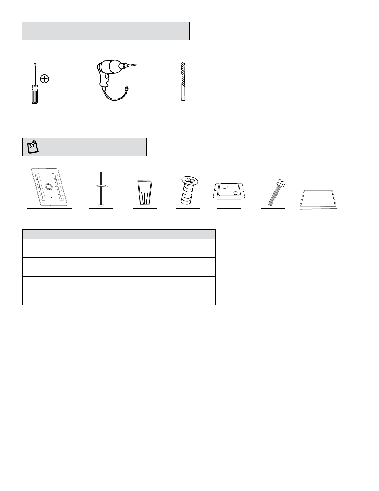
Herramientas Necesarias ..........................10
Materiales Incluidos...............................10
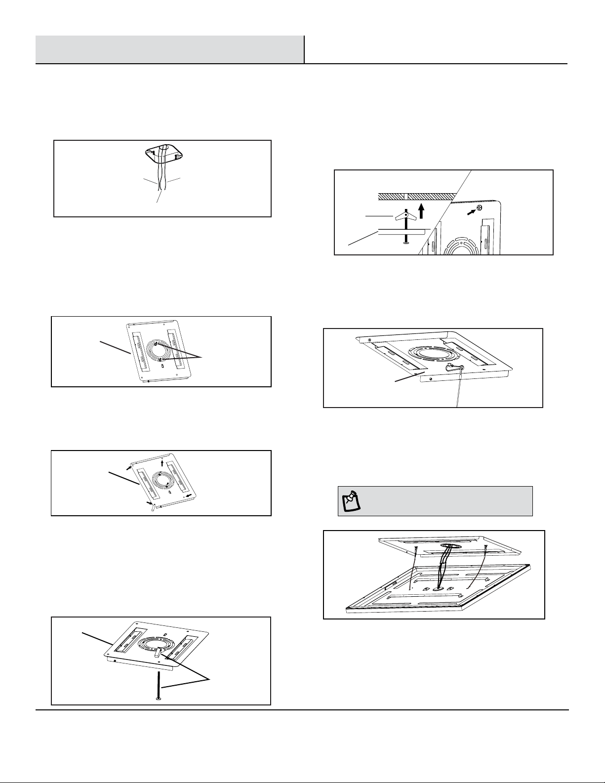
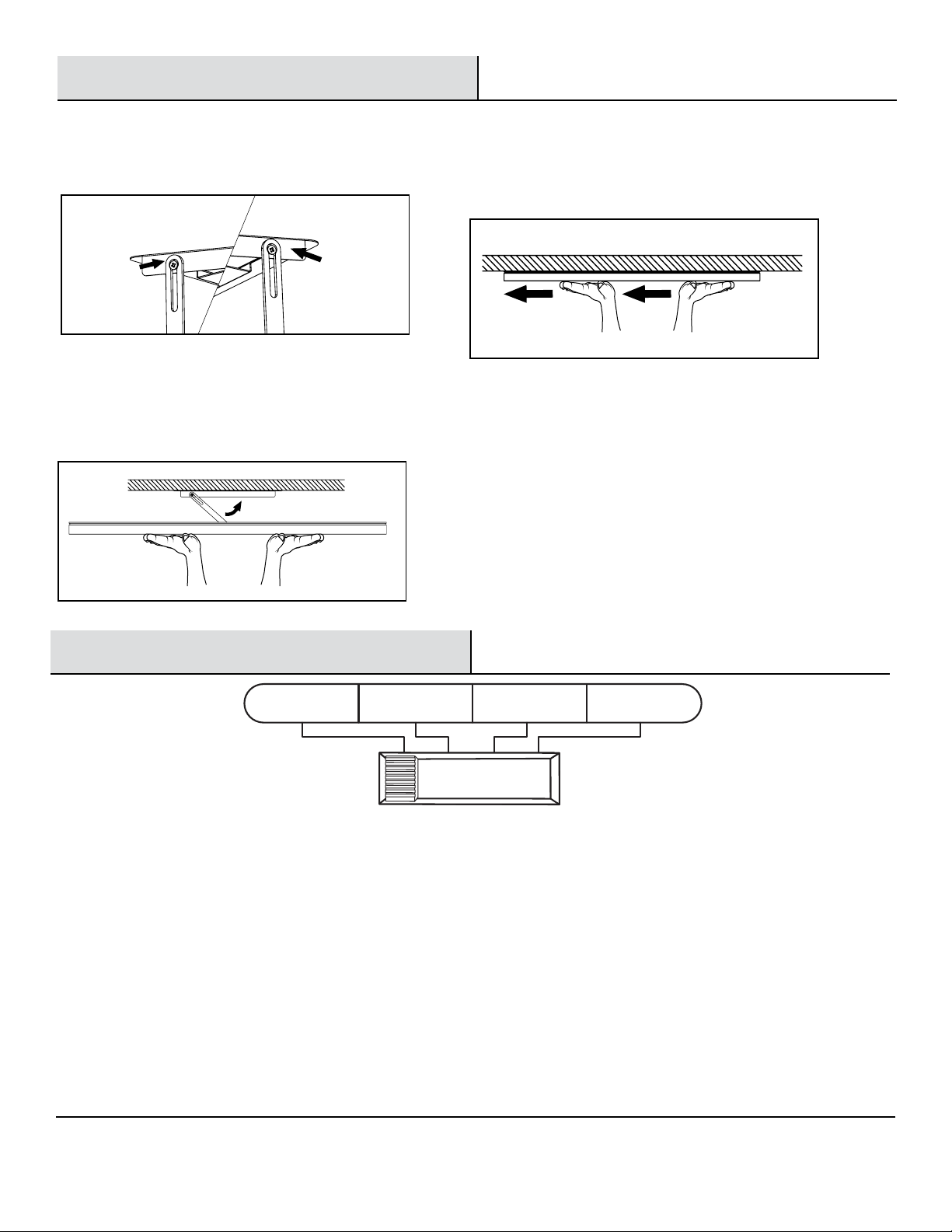
Instalación ....................................11-13
Información de Seguridad
Para su seguridad, siempre recuerde de:
□Apague la alimentación eléctrica en la caja de fusibles o breaker
antes de instalar la lámpara.
□Conecte la lámpara a tierra para evitar choque eléctrico y para
asegurar que lámpara encienda seguramente.
□Verifique todas las conexiones pare asegurarse que esten apretadas
y correctas.
□Use zapatos de suela de caucho y trabaje en una escalera fuerte de
madera.
□Cuente todas las partes pequeñas y destruya los materiales de
empaque porque estos pueden ser peligrosos para niños.
Esta lámpara está diseñada para uso en un circuito protegido por un
fusible o un breaker. También está diseñada para ser instalada de
acuerdo con los códigos eléctricos locales. Si no está seguro acerca
de su cableado, consulte a un electricista calificado o al inspector de
electricidad local y verifique su código eléctrico local.
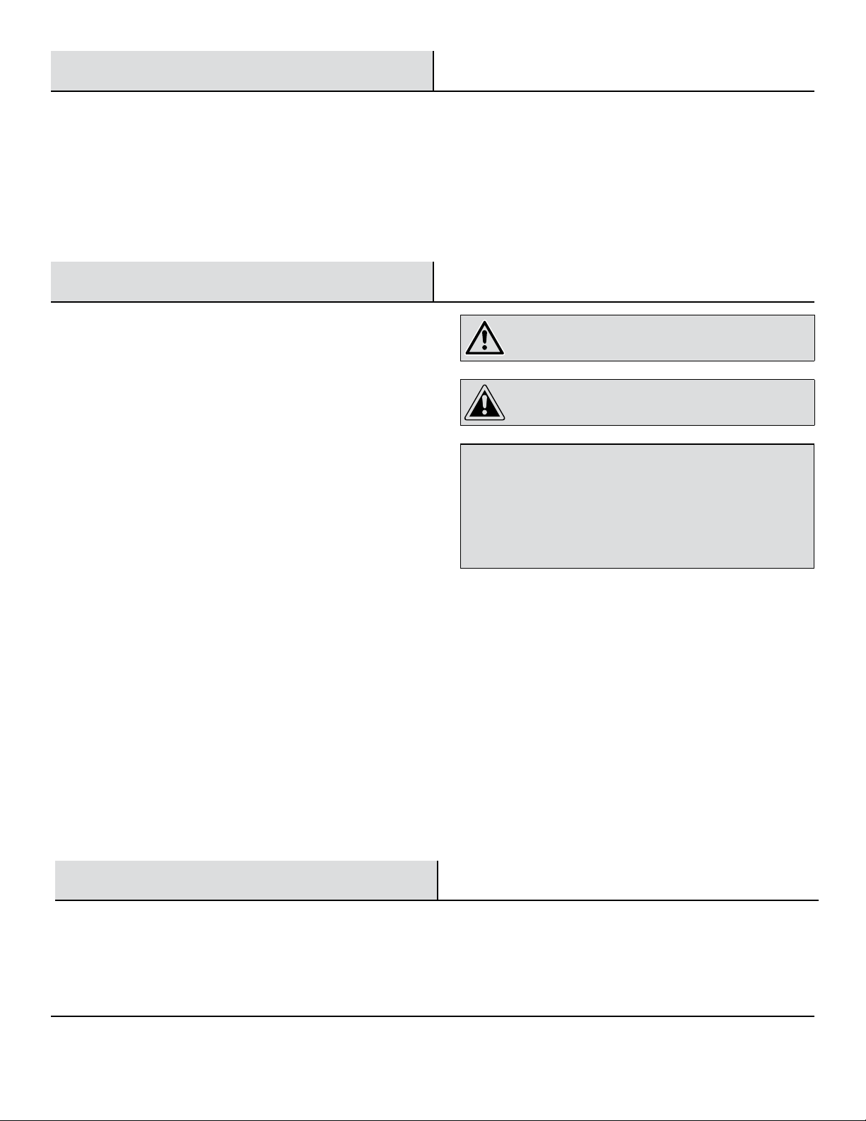
ADVERTENCIA: RIESGO DE DESCARGA
ELÉCTRICA. La corriente eléctrica de una casa puede
causar una descarga dolorosa o una lesión seria al menos
que se maneje adecuadamente.
PRECAUCIÓN: Apague la alimentación principal en
el breaker antes de instalar el aparato, con el fin de evitar
posibles descargas.
AVISO: Todas las conexiones eléctricas deben estar de acuerdo con
las normas del Código Eléctrico local y Nacional (NEC). Si no está
familiarizado con las conexiones de cableado eléctrico adecuado
obtenga los servicios de un electricista calificado.
Retire la lámpara y el paquete de montaje de la caja y asegúrese de
que no falte ninguna pieza haciendo referencia a las ilustraciones de
las instrucciones de instalación.
Garantia
GARANTIA LIMITADA
Este producto está garantizado de estar libre de defectos de fabricación y materiales por un máximo de 5 años a partir de
la fecha de compra. Si no lo hace, por favor póngase en contacto con el Equipo de Servicio al Cliente al 1-877-527-0313 o visite www.
HomeDepot.com.
9 HOMEDEPOT.COM
Para asistencia llame al 1-877-527-0313.
Este dispositivo cumple con la Parte 15 de las Reglas de la FCC. La operación está sujeta a las siguientes dos
condiciones, este dispositivo: 1) no puede causar interferencia perjudicial, 2) debe aceptar cualquier interferencia
recibida, incluida la interferencia que puede causar interferencia perjudicial. Nota: Este equipo ha sido probado y cumple
con los límites para un dispositivo digital de Clase B, de conformidad con la parte 15 de las Reglas de la FCC. Estos
límites se establecen para proporcionar una protección razonable contra interferencias perjudiciales en una instalación
residencial. Este equipo genera, utiliza e irradia energía de radiofrecuencia y puede causar interferencias perjudiciales
en las comunicaciones de radio si no se instala y utiliza correctamente. Sin embargo, no puede garantizarse que
no ocurrirá interferencia en una instalación en particular. Si este equipo causa interferencias perjudiciales en las
comunicaciones de radio o televisión, que pueden detectarse encendiendo y apagando el equipo, el usuario puede
intentar solucionar el problema mediante una de las siguientes medidas: reorientar o reubicar la antena receptora
. Aumente la distancia entre el equipo y el receptor. Conecte el equipo a un tomacorriente que no esté en el mismo
circuito al que está conectado el receptor. Consulte al proveedor oa un técnico experimentado de radio / TV para obtener
ayuda. Cualquier cambio o modificación no aprobada expresamente por el fabricante podría anular la autoridad del
usuario para operar el equipo.
DECLARACION DE LA FCC
Declaración de Conformidad del Proveedor:
47 CFR § 2.1077 Compliance Information
Partido Responsable:Feit Electric Company
4901 Gregg Road,
Pico Rivera, CA 90660, USA
562-463-2852
Uentificador Único:
FP2X2/4WY/WH/HDT

10
Pre-Instalación
HERRAMIENTAS REQUERIDAS
PIEZAS INCLUIDAS
NOTA : Piezas no mostradas a tamaño real.
Pieza Descripción Cantidad
AA Placa de montage (13,3 in. x 21,6 in. x 0,47 in.) 1
BB 3/16 pulg. Perno de palanca 4
CC Tuercas de Cable 3
DD Tornillos #8-32 x 1 in. 2
EE Cubierta del cableado 1
FF Caleado tornillos de la tapa 2
A Panel LED 2X2 lámpara plano 1
destornillador
de cruz
taladro
eléctrico
Broca de 1/2 pulg.
AA BB CC DD EE FF A

11 HOMEDEPOT.COM
Para asistencia llame al 1-877-527-0313.
□Conecte el cable de voltaje de línea (negro) a la
fuente de alimentación del edificio con las tuercas
de cable (CC).
□Conecte el cable neutro (blanco) al edificio común
con las tuercas de cable (CC).
□Conecte el cable de tierra (verde / amarillo) que
está conectado a la parte posterior del panel al
suelo del edificio con las tuercas de cable (CC).
□Coloque todas las conexiones de cableado en la
cubierta del cableado (EE) y coloque la cubierta del
cableado (EE) en la parte posterior del aparato.
□Pre-atornille ambos tornillos de la cubierta del cable
(FF) en el accesorio y deslice la ranura de la cubierta
del alambre en un tornillo.
□Presione la cubierta del cable (EE) hacia abajo y
coloque el otro tornillo para entrar en el ojo de la
cerradura y apriete los tornillos para asegurar la
cubierta del cable (EE).
NOTA: Los cables de alimentación del edificio
deben ser mín. 90 ° C.
ADVERTENCIA: El peso del panel Edge Lit no está
diseñado para ser soportado por la rejilla del techo.
Debe estar atado de nuevo a la estructura. El no hacerlo
puede causar lesiones graves.
NOTA: Dos conductores de circuito
derivado de 12 AWG, un conductor de
tierra aislado de 12 AWG y tres 18Awg
para el cableado de la luminaria.
EE
conducto
conector
Instalación (T-Bar Techo)
1 Preparación para la instalación
2 Asegurar el Panel
3 Colocación de la placa de montaje
□Prepare la cubierta del cableado (EE) suministrada en el kit
de cableado.
□Coloque el panel de borde iluminado en la ubicación
deseada y asegúrelo a la estructura del edificio usando un
cable (no incluido). Ate los alambres de la estructura a los
cables de soporte del accesorio.
□Conecte el conector del conducto (no incluido).
□Alimente los cables de alimentación del edificio a través del conector
del conducto y el conducto fl exible entrante (no incluido).
neutral
CC
EE
FF
EE
linea de voltaje
suelo
cable
NOTA: Seleccione la temperatura de color preferida
utilizando el interruptor detrás del dispositivo. Consulte “Cómo
cambiar las configuraciones de color” en la página 13.

12
Instalación
1 Identificando los Cables
2 Instalando la Placa de Montaje
□Instale la placa de montaje (AA) a la caja de conexiones
usando los dos tornillos # 8-32 x 1 (DD) proveidos.
□Alinee la placa de montaje en la dirección que desea
que el dispositivo alineado. Una vez que se instalan los
pernos de anclaje, no se puede cambiar la orientación.
3 Posicionando Pernos de Palanca
4 Asegurando Pernos de Palanca
5 Re-Instalando la Placa de Montaje
6 Conexión de la luz del panel
7 Instalación de la luz del panel
□Usando la placa de montaje (AA) como guía, marque la
posición de los orificios en el techo o la pared donde se
colocarán los pernos de palanca.
□Retire la placa de montaje (AA) de la caja de conexión.
□Taladre los 4 agujeros marcados usando broca de 1/2 pulg.
□Quite las mariposas de los pernos 3/16 pulg. (BB).
□Inserte el perno (BB) por la parte delantera de la placa de
montaje (AA) y vuelva a colocar la mariposa en el perno
(BB). Repita el procedimiento para los 4 pernos.
□Enganche el cable de soporte del accesorio en la placa
de soporte de montaje (AA).
linea de voltaje cable de tierra
neutral
AA
DD
BB
12
AA
BB
AA
AA
□Desconecte la alimentación principal del disyuntor antes de
instalar el aparato.
□Identifique el cableado: (línea negra, blanco - neutro y
verde - tierra)
□Introduzca los cables de la caja de conexiones a través del
centro del agujero de la placa de soporte de montaje (AA).
□Una vez que las alas (BB) están a través y expandido, tire
del tornillo (BB) hacia abajo para enganchar y apretar.
□Vuelva a colocar la placa de montaje (AA) insertando los
cuatro pernos de palanca (BB) en los orificios perforados.
NOTA: Seleccione la temperatura de color preferida utilizando
el interruptor detrás del dispositivo. Consulte “Cambiar la
configuración de color” en la página siguiente.
□Conecte los tres cables que vienen del accesorio a
los cables de la caja de conexiones (verde - tierra,
negro - voltaje de línea y blanco - neutral)
AA

13 HOMEDEPOT.COM
Para asistencia llame al 1-877-527-0313.
Instalación (continuado)
□Inserte la ranura del orificio del brazo oscilante en el
tornillo de sujeción de la placa del soporte de montaje.
□Alimente la caja de conexiones y los cables del
accesorio a través del orificio central de la placa del
soporte de montaje.
□Levante el accesorio en la dirección de la flecha en el
brazo oscilante.
□Una vez que el dispositivo se ha elevado y está al
ras del techo, bloquear el dispositivo moviéndolo
hacia la dirección opuesta que se levantó.
8 Conexión de los brazos oscilantes
9 Colocación del panel de luz
10
Asegurar el panel de luz
Cambiar la configuración de color
1. Blanco Suave - Blanco Brillante - Luz de Día -
Interruptor Marcas en la lámpara: SW-BW-DL-Switch
2. Cuando el interruptor deslizante está ajustado a SW
(Blanco Suave), la temperatura de color se fija en
3000K.
3. Cuando el interruptor deslizante está ajustado a BW
(Blanco Brillante), la temperatura de color se fija en
4000K.
4. Cuando el interruptor deslizante está ajustado a DL
(Luz de Día), la temperatura de color fija en 5000K.
5. Cuando el interruptor deslizante está ajustado a
SWITCH, la temperatura de color se puede cambiar de
SW-BW-DL con el interruptor de luz existente.
6. Para cambiar las temperaturas de color usando su
interruptor de luz existente:
A. Coloque el interruptor deslizante en la parte posterior
del aparato en “SWITCH”.
B. Encienda y apague el interruptor de la luz dentro de 0.5-3 segundos para
recorrer las tres temperaturas de color diferentes.
C. El dispositivo recordará la última temperatura de color seleccionada
después de que el dispositivo haya estado en una temperatura de color
seleccionada durante 10 segundos y finalmente se haya apagado. Para
mantener el color seleccionado, no mueva el interruptor como se detalla
en el paso anterior, déjelo apagado durante 10 segundos. La próxima vez
que encienda el dispositivo, el dispositivo emitirá la última temperatura
de color seleccionada.
7. La función de restablecimiento se utiliza cuando se utilizan varios productos
de iluminación seleccionables por color que funcionan con el mismo
interruptor de luz. En caso de que los accesorios múltiples no muestren
el mismo color al mismo tiempo, los accesorios deben ser REAJUSTADOS
utilizando su interruptor de luz existente. Simplemente apage y prenda
el interruptor de pared 7 veces en 10 segundos. (Por ejemplo, con el
accesorio en la posición ON, encienda y apage el interruptor de pared en
aproximadamente 1 a 1.5 segundos. Repita 7 veces.)
SW BW DL Switch
(Blanco Suave) (Blanco Brillante) (Luz de Día) (Interruptor)

Preguntas, problemas, piezas que faltan ? Antes de regresar a la tienda,
llame a Commercial Electric Servicio al Cliente
8 a.m. - 7 p.m., EST, Lunes - Viernes, 9 a.m. - 6 p.m., EST, Sábado
1-877-527-0313
HOMEDEPOT.COM
Conserve este manual para uso futuro.
Table of contents
Languages:
Other Commercial Electric Light Fixture manuals

Commercial Electric
Commercial Electric 53804101 User manual

Commercial Electric
Commercial Electric SKU 445-997 User manual

Commercial Electric
Commercial Electric DAWN12-PC-3K-BZ User manual

Commercial Electric
Commercial Electric TITLE20 User manual

Commercial Electric
Commercial Electric 54197201 User manual

Commercial Electric
Commercial Electric SKU 843-093 User manual
Popular Light Fixture manuals by other brands

MaxLite
MaxLite MPulse MP-SM Series installation manual

Future light
Future light DMH-75 Infinity user manual

Lightolier
Lightolier Calculite 8011WW specification

LARSON
LARSON EXP-EMG-EXT-42W SERIES Installation & operation manual

Maverick
Maverick Storm 4 Profile user manual

JONATHAN Y
JONATHAN Y JYL9022A manual