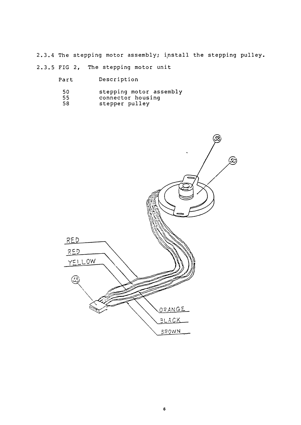
Commodore 1540 User manual

Commodore
Single Disk Drive
Technical Manual
Model 1540/1541
r
T
CvM O tOTCOO;
— ''•■■* .s&" ** * i
' O - . :-! i>v’y : - ^' "*
C
M
M
These documents are for re air service information oniy. Part numbers are for reference
oniy. Oniy arts on current ceaier arts list are available. No iicense is given for any use by
ocssess.'on of these documents ana may not be re roduced in any form without the written
a roval of Commodore Electronics Limited.
^32?
f «
t, • ; c o o a o r e
COMPUTER

CONTENTS
Chapter 1
1.1 Scope
1.2 Unpacking
1.3 Protection against noise
1.4 Input-Output cable
1.5 DC power source
1.6 Initial inspection
1.7 Outline of fucntions
1.8 Read/Write Head
1.9 Track positioning echanis
1.10 Spindle drive echanis
1.11 Eject echanis
Chapter 2
2.1 Mechanis explanation
2.2 Functional explanation
2.3 Asse bly procedure
Chapter 3
3.1 Description
3.2 Operating procedure
3.3 Media handling procedure
3.4 Seek error
3.5 Write error
3.6 Read error
3.7 Description
3.8 Head cleaning
3.9 Adjust ent procedure
3.10 Li iter Adjust ent Procedure
3.11 Diag Test (Burn-in) Procedure
3.12 Parts list for 1541

Chapter One
1.1 Scope
In this chapter, a desciption is ade of the proceedures necessary
for servicing the Model 1540/1541 Floppy Disk Drive.
1.2 Unpacking
Special care should be exercised during unpacking not to da age the
unit.
Unpacking proceedures are as follows:
a) Re ove cardboard sleeve fro styro-foa box
b) Open 'styro-foa ' box and re ove drive
c) Check the drives front door for proper operation
********************************
* *
* Caution *
* *
* Do Not Use Magnetized Tools *
* *
********************************
1.3 Protection against noise
A week signal fro the edia is detected in the head section of the
drive. Hence, do not install the drive near a TV set or other areas
where electro agnetic noise is generated. (i.e. otors, air-
conditioners, etc)
1.7 Input/Output Cable
The length of the cable between the host and the drive (between the
host and the last drive when the drives are daisy chained) should
not exceed 5 eters (16 feet) .
1.8 DC power source
The drive is powered by a internal power supply providing the drive
with +12V and +5V.
Initial inspection
2

1.10
The drive can be briefly inspected for its operation by the
following proceedure. Install the drive, connect the power and I/O
cables. Turn drive on and ake sure the front panel power la p is
on. Proceed to step 2.2.
Outline of functions
The 1540/1541 Minifloppy Disk Drive echanis is co posed of the
data read/write head, track positioning echanis , spindle drive
echanis and eject echanis .
1.11 Read/Write Head
The. Read/Write head uses a glass-bonded, ferrite/cera ic head.
Track-to-track erasing is acco plished by the straddle erase ethod.
The surface of the Read/Write head is irror-ground to ini ize
weear of the head and edia. Also, the head is desighned in such a
way that the axi u signal can be obtained fro the edia surface.
1.12 Track positioning echanis
Positioning of the Read/Write Head is acco plished by a stepping
otor and steel belt. The stepping otor rotates clockwise or
counter-clockwise by two steps per track. The control circuit on the
logic board selects the direction and nu ber of step to the desired
track.
1.13 Spindle drive echanis
The spindle drive otor operates on 12 VDC and turns the spindle,
through a belt drive, at 300 revolutions per inute. The speed of
the drive otor is controlled by a feedback signal fro a tacho eter
which is housed in the drive otor asse bly. The feedback signal
controls a servo a p that supplies the 12 VDC drive current.
1.14 Eject echanis
When the edia is inserted in the Disk Drive and the door is closed
the edia is cla ped by the spindle and hub. At this ti e the
ejector echanis is loaded by the insertion of the disk and locked.
When the door is opened, the ejector echanis is unlocked and the
edia pops out of the door.
3

Chapter Two
2.1 Mechanis Explanation
The 1540/1541 echanis is installed in the syste horizontally,
however the drive will fuction if ounted vertically. The
echanical parts of the drive include an alu inu chassis, a
stepping otor, head positioning asse bly, drive otor, a hub and
spindle asse bly for centering and retaining the edia during
operation. The agnetic head is of a glass cera ic construction.
2.2 Function explanation
The drive is itself an independent e ory device. The drive is
co posed of a edia cla p rotating jnechanis , ahead positioning
echanis and an eject echanis . When the front door opens, the
edia can be inserted. All positioning operation excluding insertion
and re oval of the edia are controlled by the internal guide
echanis . Closing the front door causes the edia cla p echanis
to operate. Two operations are perfor ed in the following order:
a) The edia is centered.
b) The edia is cla ped and retained between the spindle and the
hub.
The spindle and hub rotate at 300 r.p. . through a closed-loop
control circuit e ploying a D.C. otor/tacho eter. It is i portant
that the relationship between the head and the edia is aintained
correctly during operation. For this purpose, a pressure pad is
used to hold and press down the edia (about 12g) fro the opposite
side of the head, to aintain the correct contact with the head.
This head asse bly is coupled by a etal band to a four phase
stepping otor the perfor s the track positioning. One step of the
stepping otor corresponds to a 1/2 track ove ent. Use of a high
speed stepping otor and etal band drive, this series of disk
drives can perfor access operations at a very high speed.
2.3 Asse bly procedure
2.3.1 The.housing asse bly; install the eject pin and the spindle.
2.3.2 The housing asse bly; on the reverse side install the spindle
pulley.
4

2.3.3 FIG 1, The housing unit.
Part Desciption
22 spindle
33 housing asse bly.
53 eject pin
5

2.3.4 The stepping otor asse bly; install the stepping pulley.
2.3.5 FIG 2, The stepping otor unit
Part Description
50 stepping otor asse bly
55 connector housing
58 stepper pulley
6

2.3.6 The D.
2.3.7 FIG 3,
Part
44
48
51
59
. otor asse bly; install the otor pulley.
D.C. otor and control PCB
Description
otor control PCB
D.C. otor
connector housing
D.C. otor pulley
7

FIG. 6
Part Description
20 binder screw
21 diskette guide
28 LED cla p
29 front panel
30 Flush screw
31 LED asse bly
32 LED holder ring
Part Description
37 washer
38 eject spring
39 eject plate
40 slider
43 diskette guide
52 connector housing
(c?. 8

FIG 7.
Part Description
15 binder screw
18 binder screw
24 tension pulley
9

nTr* o
r jl vj o
Part Description
20 binder screw
45 cable cla p
49 cable ties
10

FIG 9
Part Description Part Description
1door asse bly 13 hub support
2 collar 14 hub fra e
3cla p spring 15 binder screw
5thrust washer 16 spring washer
6collet asse bly 17 ar support asse bly
7hub spring 18 binder screw
8hub 19 pad plate asse bly
9hub shaft 27 hinge spring
10 door spring 60 collet
11 E-washer 61 collet bearing

2.3.8 FIG. 4, Diskette guide, LED asse bly and connector housing.
Part Description
31 LED asse bly
43 diskette guide
52 connector hous
12

2.3.9 Secure the D.C. otor fro the reverse side of the housing asse bly
with two screws.
2.3.10 Put the otor control PCB into hole 'A' and serure it with two
screws.
2.3.11 Secure the stepping otor with two screws.
2.3.12 Secure the carraiage stopper with a screw.
2.3.13 Install the connector housing ’52’ into the hole 'B' and re ove
through hole 'C'.
2.3.14 Sercure the two diskette guides '21' and '43' with two screws each.
2.3.15 Install the LED holder in the front panel.
2.3.16 Insert the LED asse bly into the LED holder ring.
2.3.17 Install the led into the LED holder, then push the LED holder ring
onto the LED holder.
2.3.18 Attach the front panel with four flush screws.
2.3.19 Secure the eject plate with a screw.
2.3.20 Wind the etal band around the tension pulley.
2.3.21 Insert the guide shafts into the head asse bly. Install the tension
pullet as shown in figure 8
2.3.22 Secure the guide shaft keepers by two screws each.
2.3.23 Wind the etal band around the stepper pulley and secure it with a
screw to the stepper otor pulley.
2.3.24 Hook the spring to the tension pulley and install unit in the slot
in the housing asse bly.
2.3.25 Hook the opposite end of the spring to the housing asse bly.
2.3.26 Fasten cable ties to the cables.
2.3.27 Secure the cable cla p with a screw as shown in FIG 8.
2.3.28 Secure the ar support asse bly with a screw to the hub support.
2.3.29 Insert the hub shaft into the hub, the hub spring, the collet assy,
the thrust washer, the collar, the cla p spring and two collars.
2.3.30 Insert the hub shaft into the fra e and the hub support and fasten
it at the E-washer.
2.3.31 Set the door asse bly and the door spring at the hub fra e.
2.3.32 Secure the pad plate asse bly with a srew to the fra e at the
location shown in FIG 9
2.3.33 Secure the two hinge springs with two srews each.
13

FIG. 5
Part Description
18 binder screw
20 binder screw
37 washer
41 spring washer
42 carriage stopper
44 otor control PCB
50 stepping otor as
14

2.3.36
2.3.37
2.3.38
Place the belt over the D.C. otor pulley and partially on the
spindle pulley.
By turning the spindle pulley the rest ot the belt will seat
co pletely on the pulley.
FIG 10
Part Description
12 drive belt
15

2.3.39 FIG 11; Co pleted Drive Mechanis
@5=91 15:
OO
_ r
O
r,
lc •=i i-i i
o i
16
ifr nn

Chapter Three
3.1 Description
Since the disk drive is placed under direct control of the
interface and power supply, no special proceeedure is required for
starting and operation.
3.2 Operating procedure
Make sure that the power supply and I/O connector are connected,
then insert the disk in accordance with the following procedure .
3.2.1 Inserting the edia
a) Apply DC voltage to the drive.
b) Open the front door.
TZ.
?usn
c) With the index hole and write protect notch being placed on the
left side of the jacket, push the rpedia in, when the edia is
fully inserted the loacking action can be felt.
d) Push the door downward and close the aoor so that it is locked
fir ly
Extracting the ed ia
a) Open the front door. The edia will pop out auto atically to a
position where you can extract it easily.
b) For protect ion of the recorded data, the edia should always be
stored in its envelope.
c) Close th door of the drive.
3.3 Media handling procedure
Since the edia has been sudjected to awrite operation i naturally
contains i for ation, adequate attention ust be paid to its
handling.
In order to extend the life of the edia and eli inate the causes
of errors, it is best to take the following steps:
17

a) When writing so ething on the jacket label of the edia, do
not use a ball point pen or pencil, use felt-tipped pens.
b) Do not hold the edges of the edia with paper clips or the
like.
c) Do not touch the edia exposed in the slot of the jacket.
d) Do not atte pt to clean the edia.
e) Do not keep the edia in the areas where there is a strong
agnetic field.
f) The diskette should be kept in its jacket.
g) Special care should be exercised st> that the edia is kept free
fro liquid, dust, etal particles, etc.
h) Take care not to exceed the following environ ental conditions:
Te perature 10 to 47 °C
Relative hu idity 20 to 80 %
3.4 Seek error
Few seek errors will be experienced due to the low stepping rate,
less than 12 sec/track. In case of a seek error, however,
recalibration of track position can be perfor ed. This can be done
by repeatedly stepping the head towards track 0 untill track 0
status is detected.
t.5 Write error
In order to check the quality of the data, perfor a read-after
write operation. When data can not be read, rewrite that track and
sector once again.
When data can not be read after four such operations track is
defefective.
3.6 Read error
What happens quite often when perfor ing a read operation is a soft
error. A soft error is defined to be a read error which is
recoverable by aking ten or less read operations. However, in the
event no recovery is ade in ten operations, ove one step fro the
track in the sa e direction as the previous step, then return one
step. If this fails to read the data, this error is unrecoverable.
18

3.7 Description
Periodic aintenance is indispensable so
peripherial equip ent operates properly,
i portant to periodically clean the head and
Repairs and adjust ents should be ade in
proceedures below.
that this type of
It is particularly
check the load pad.
accordance with the
3.8 Head Cleaning
Check for excessive dust or agnetic oxide on the load pad. With
the door open (do not ove upper ar greater that what, is provided
by opening the front door) clean head with lint free cotton cloth
or !Q-tip' in 91/ isopropyl alcohol. Wipe the head carefully to
re ove any dust and/or oxide.
3.9 Adjust ent Procedure
In case of a alfuction or parts replace ent, ake the following
adjust ents. In order to aintain the interchangability of the
edia between drives it is desirable check each drive against a
aster align ent diskette.
3.9.1 Track adjust ent (radial track)
a) Connect I/O cable an restore the head to track 00.
b) Insert a 48tpi align ent diskette and close the door.
c) Connect two oscilloscope probes to pin 1 and pin 14 of UH6
(592), set oscilloscope to angbraic add at 50 V/c and 200
sec/div.
d) Load the head and allow it to seek to track 16, check for cats
eye wave for . When the cats eye lobe ratio is 70/ or less,
loosen the stepping otor ounting screws, turn the stepping
otor to obtain the lobe ratio of 90/ or less.
e) After allowing the head to track 34, return it to track 16 and
recheck the cats eye. If the ratio is correct tighten the
stepping otor screws.
4X i o o ^ 10
Cats eye lobe ratio
19
Other manuals for 1540
1
This manual suits for next models
1
Table of contents