S&S Northern ODE-3-110023-101 User manual

Optidrive E3 Simple Set-Up Guide
(0.37kW~37kW)
V2.0.0

Optidrive E3 Set-up Guide
Contents
Section
Heading
Page
1
Safety & General Information
1
2
Basic
Technical Data
2
3
Display & Keypad
3
4
Control Terminals
6
Power terminals & Motor Connections
8
6
Basic
EMC
Information
11
7
Getting Started
1
9
8
Parameter P
-
1
2
3
9
Keypad Control
2
9
10
Analogue Inputs
3
4
1
1
Analogue
/Digital
Output
3
1
2
Relay Output
3
6
1
3
Start Mode & Auto Restart
3
7
1
4
Motor Control
3
8
1
DC Injection braking
4
3
1
6
Dynamic Braking
4
7
1
7
Read Only Status Parameters
0
1
8
Fire Mode
4
1
9
Trip Codes
20
IP66 Switched
Units
6
2

Optidrive E3 Set-up Guide P a g e | 1
1
Safety & General Information
Safety Information
Please read and observe the safety information in the Invertek Optidrive E3 Installation and Operating
Instruction User Guide.
This Set-Up Guide does not contain safety information as it is assumed that the customer has read and
understood the safety information in the Optidrive E3 Installation and Operating Instruction User Guide.
General Information
The contents of this Set-Up Guide are believed to be correct at the time of printing. In the interests of
continuous improvement, the authors reserve the right to change the contents of the Set-Up Guide ithout
notice.
All rights reserved. No part of this Set-Up Guide maybe reproduced or transmitted in any form or by any
means, electrical or mechanical, including photocopying, recording or by any information storage or retrieval
system, ithout permission in riting from the publisher.
General information a out this Set Up Guide
This set up guide gives basic information on setting up the Optidrive E3 in terminal and keypad control. It gives
information on ho to change the terminal configuration to suit a particular application requirement.
This set up guide gives information on the operation of various parameters to allo the user to set the drive up
to their particular requirements.
Optidrive E3 Software
This set up guide as ritten ith reference to the latest version of Optidrive E3 soft are – V3.08. Depending
on the age of the drive, some of the features described in this set up guide may not be available.

P a g e | 2 Optidrive E3 Set-up Guide
2
Basic Technical Data
E3 Basic Technical Data
All of the E3 drives below are 3 phase output
Model Number Frame
size
Input
voltage
Number
of input
phases
utput
voltage
kW utput
current
Internal
EMC
filter
Internal
braking
transistor
ODE-3-110023-101# 1
110 to
11 VAC
±10%
1
0 to
230V
(2 0V
max)
(Voltage
doubler)
0.37 2.3 No No
ODE-3-110043-101# 1 0.7 4.3 No No
ODE-3-2100 8-104# 2 1.1 .8 No Yes
ODE-3-120023-1F1# 1
200 to
240VAC
±10%
1
0 to
230V
(2 0V
max)
0.37 2.3 Yes No
ODE-3-120043-1F1# 1 0.7 4.3 Yes No
ODE-3-120070-1F1# 1 1. 7 Yes No
ODE-3-220070-1F4# 2 1. 7 Yes Yes
ODE-3-22010 -1F4# 2 2.2 10. Yes Yes
ODE-3-3201 3-1&4# 3 4.0 1 .3 No Yes
ODE-3-120023-301# 1
200 to
240VAC
±10%
3
0 to
230V
(2 0V
max)
0.37 2.3 No No
ODE-3-120043-301# 1 0.7 4.3 No No
ODE-3-120070-301# 1 1. 7 No No
ODE-3-220070-3F4# 2 1. 7 Yes Yes
ODE-3-22010 -3F4# 2 2.2 10. Yes Yes
ODE-3-320018-3F4# 3 4.0 18 Yes Yes
ODE-3-320240-3F4# 3 . 24 Yes Yes
ODE-3-420300-3F4# 4 7. 30 Yes Yes
ODE-3-420460-3F4# 4 11 46 Yes Yes
ODE-3- 20610-3F42 1 61 Yes Yes
ODE-3- 20720-3F42 18. 72 Yes Yes
ODE-3-140022-3F1# 1
380 to
480VAC
±10%
3
0 to
400V
( 00V
max)
0.7 2.2 Yes No
ODE-3-140041-3F1# 1 1. 4.1 Yes No
ODE-3-240041-3F4# 2 1. 4.1 Yes Yes
ODE-3-2400 8-3F4# 2 2.2 .8 Yes Yes
ODE-3-24009 -3F4# 2 4 9. Yes Yes
ODE-3-340140-3F4# 3 . 14 Yes Yes
ODE-3-340180-3F4# 3 7. 18 Yes Yes
ODE-3-340240-3F4# 3 11 24 Yes Yes
ODE-3-440300-3F4# 4 1 30 Yes Yes
ODE-3-440390-3F4# 4 18. 39 Yes Yes
ODE-3-440460-3F4# 4 22 46 Yes Yes
ODE-3- 40610-3F42 30 61 Yes Yes
ODE-3- 40720-3F42 37 72 Yes Yes
For IP20: Replace # with a ‘2’
For IP66 Non-switched: Replace # with a ‘A’
For IP66 switched: Replace # with a ‘B’
ODE-3-3201 3-1&4#: Replace ‘&’ with a ‘0’ for IP20 – no internal EMC filter. Replace ‘&’ with ‘F’ for IP66 –
internal EMC filter fitted

Optidrive E3 Set-up Guide P a g e | 3
3
Display & Keypad
Display and Keypad
The Optidrive E3 has a LED display and 5 push buttons that allow the user to monitor the drives operation,
adjust parameter values, reset a drive trip and also ontrol the drive in keypad ontrol (IP66 Outdoor rated
keypad shown)
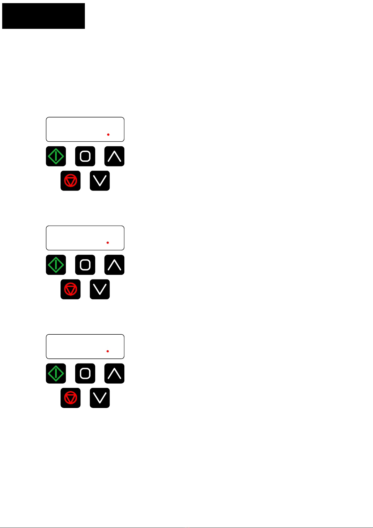
Resetti
ng to factory default parameters
Changing parameter values
StoP
Press and hold the
NAVIGATE button >2s
to go into the
parameter menu
P-01
Use the UP and
DOWN buttons to
select the required
parameter
P-08
Press and release the
NAVIGATE button to
select parameter edit
mode
10 00
Adjust to tge required
value using the UP
and DOWN buttons
Press and release the
NAVIGATE button to
return to the parameter
menu (parameter
changes are saved when
the NAVIGATE button is
pressed). Use the UP
and DOWN buttons to
select another parameter
to edit
P-08
StoP
Press and hold the
NAVIGATE button >2s
to return to the
operating display
OR
StoP
Press and hold the
UP, DOWN and STOP
buttons for >2s
P-dEF
Display will show
P-dEF
Press the STOP/
RESETbutton to reset
the drive
StoP
All parameters will
now be set to their
factor default settings
4-20F
Press the STOP/
RESET button
StoP
The display will show
StoP
after the fault
has been reset
Resetting a trip
P a g e | 4Optidrive E3 Set-up Guide
3
Display & Keypad
The display an also be used to monitor:
•Output frequen y
•Output speed
•Output urrent
•Output power
From default settings, when the drive is enabled, the display will show output frequen y:
H 500
Press and release the NAVIGATE button, the display will show Output urrent:
A 46
Press and release the NAVIGATE button, the display will show Output power:
P 72

Optidrive E3 Set-up Guide P a g e | 5
3
Display & Keypad
The display an also show motor RPM.
To show RPM on the display, set the motor rated speed into parameter P-10:
1500
When the NAVIGATE button is pressed, the display will y le from:
•Output frequen y
•Output RPM
•Output Current
•Output Power
•Output frequen y………..
NOT : On high inertia loads (fans/flywheels et .), if the display is required to show RPM, set parameter P-10 to
the syn hronous speed of the motor:
2 pole – 3000
4 pole – 1500
6 pole – 1000
8 pole – 750

P a g e | 6Optidrive E3 Set-up Guide
4
Control Terminals
Control Terminal Specification
All digital inputs are positive logic i.e. they must be connected to 24VDC to make them active.
Terminal Signal Description
+24VDC User Output +24VDC, 00mA maximum
2 Digital input Logic : Input voltage range: 8V to 30VDC
Logic 0: Input voltage range: 0V to 4VDC
3 Digital input 2
4 Digital input 3 /
Analogue input 2
When used as a digital input – as above
When used as an analogue input: 0V to + 0V, 0 to 20mA, 4 to 20mA
5 + 0VDC User output + 0VDC, 0mA maximum ( kΩ minimum pot resistance)
6 Analogue input /
Digital input 4
When used as an analogue input: 0V to + 0V, 0 to 20mA, 4 to 20mA
When used as a digital input – as above
7 0V 0V common, internally connected to terminal 9
8 Analogue output /
Digital output
Analogue output: 0 to 0V, 20mA maximum
Digital output: 0 to 24VDC, 20mA maximum
9 0V 0V common, internally connected to terminal 7
0 Status relay common Contact:
250VAC, 6A
30VDC, 5A
Status relay normally open
contact
Control terminal connection diagram – factory default functionality

Optidrive E3 Set-up Guide P a g e | 7
4
Control Terminals
Control terminals – Factory default functionality
Terminal 1
+24VDC User supply ( 00mA maximum)
Terminal 2: Stop / un (Enable)
Switch Open: Drive stopped
Switch Closed: Drive running / enabled
Terminal 3: Forward / everse
Switch Open: Motor running in forward direction of rotation
Switch Closed: Motor running in reverse direction of motor rotation
Terminal 4: Analogue speed reference / Preset speed 1
Switch Open: Motor speed controlled by analogue input (potentiometer input)
Switch Closed: Motor speed controlled by setting of preset speed (parameter P-20)
Terminal 5: +10V eference power supply
Speed potentiometer + 0V reference
Terminal 6: Analogue input 1
Speed potentiometer wiper: 0 to + 0V
Terminal 7: 0V
Speed potentiometer 0V reference
(internally connected to Terminal 9)
Terminal 8: Analogue output – motor speed
0 to + 0VDC output proportional to motor speed
(0 to 50Hz = 0 to + 0V) (20mA maximum)
Terminal 9: 0V
0V reference
(internally connected to Terminal 7)
Terminals 10 & 11: Drive healthy relay (NO - Normally Open)
Relay Open: Drive fault
Relay closed: Drive healthy
P a g e | 8Optidrive E3 Set-up Guide
5
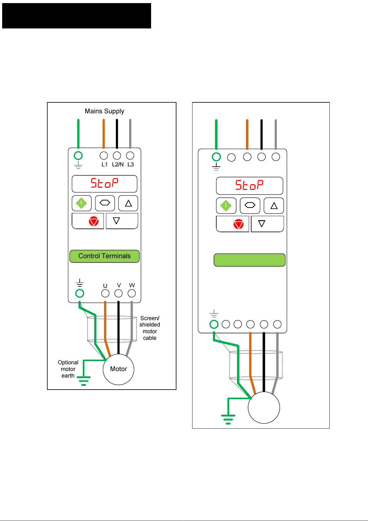
Power Terminals & Motor Connections
Power Terminals – E3 IP20
Size 1 – Mains suppl - model dependant
200V single phase input
200V three phase input
400V three phase input
Size 2, 3, 4 & 5 – Mains suppl - model dependant
200V single phase
200V three phase
400V three phase
NOTE: On E3 size 4 & 5, there are earth
connections on the drives heatsin at
the top and bottom of the drive
NOTE: For information on connecting
a bra ing resistor, see Section 15 –
Dynamic Bra ing
NOTE: Dynamic bra ing is not available
on size 1 drives
L1 L2/N L3
U V W
Motor
Mains Supply
Screen/
shielded
motor
cable
-D
+D BR
ontrol Terminals
Optional
motor
earth

Optidrive E3 Set-up Guide P a g e | 9
5
Power Terminals & Motor Connections
Power Terminals – E3 IP66
Size 1 – Mains suppl – Model dependant
200V single phase
200V three phase
400V three phase
Size 2, 3 & 4 – Mains suppl – Model dependant
200V single phase
200V three phase
400V three phase
NOTE: For information on connecting a bra ing resistor,
see Section 15 – Dynamic Bra ing
NOTE: Dynamic bra ing is not available
on size 1 drives
Screen/
shielded
motor
cable
L1 L2/N L3 U V W
Mains Supply
Motor
+D -DBR
ontrol Terminals
Optional
motor
earth
P a g e | 10 Optidrive E3 Set-up Guide
5
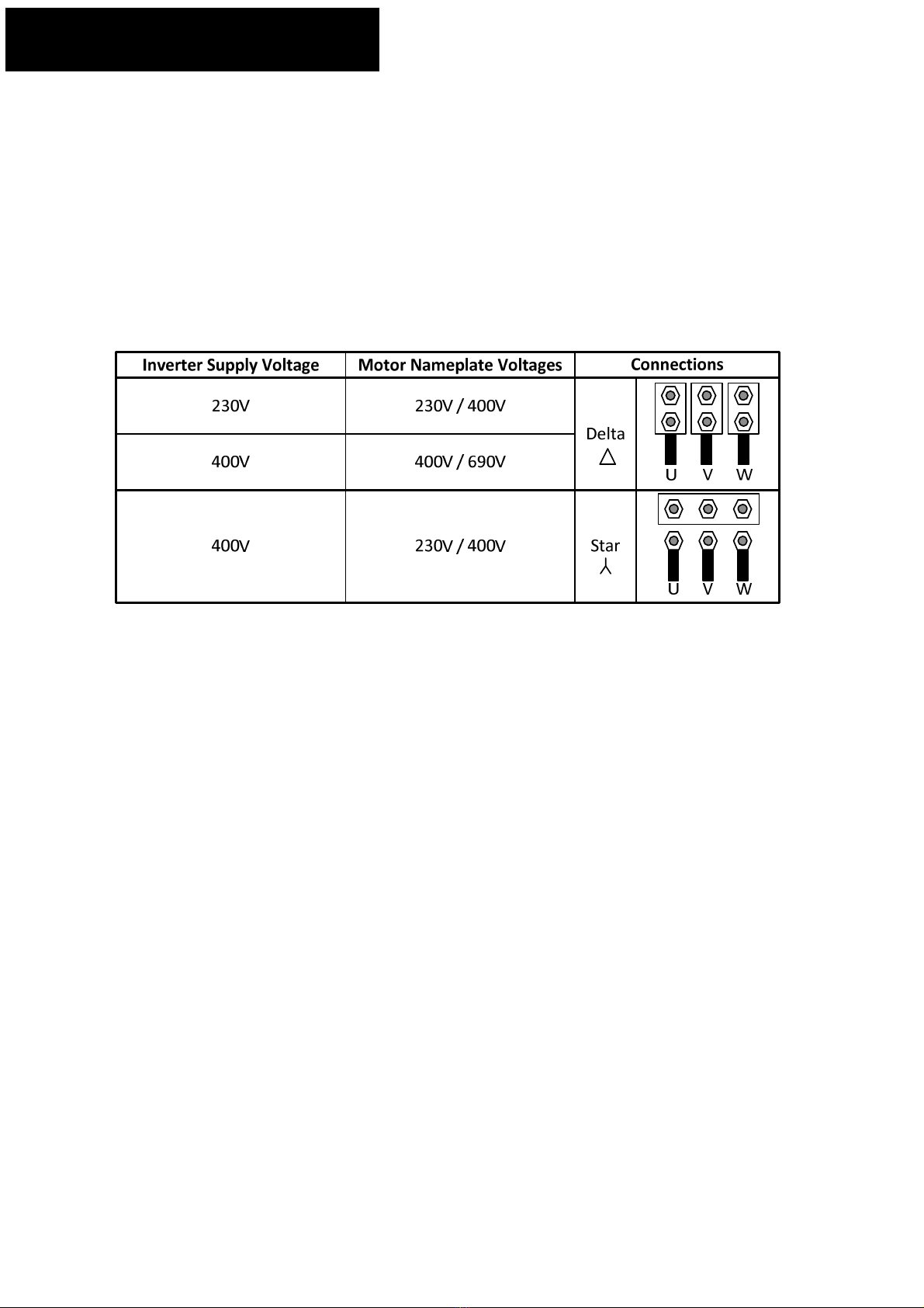
Power Terminals & Motor Connections
Motor Connections
When connecting a 3 phase motor to an AC inverter drive, it is important that the motor terminal box
connections are correct for the supply voltage being used.
Generally up to 3 W, the motor is wound for 230V delta, 400V star.
Generally above 3 W, the motor is wound for 400V delta, 690V star.
Please check our motor nameplate for the correct connection.
The usual issues when the wrong connections are made:
230V AC drive connected to a 400V star connected motor or 400V AC drive connected to a 690V star
connected motor:
The motor will probably run if starting a lightly loaded motor. If the motor tries to start a heavy load or if a
heavy load is applied to the motor while running, the motor will stall due to a lac of torque and the drive will
trip on an over current or I x t trip.
400V AC drive connected to a 230V delta connected motor:
On enable, the drive will either trip on an over current trip or the drive will go into current limit and trip on an I
x t trip.

Optidrive E3 Set-up Guide P a g e | 11
6
Basic EMC Information
Basic EMC Information
This section of this document gives some basic EMC information for the Optidrive E3.
Overview
The electromagnetic compatibility describes – according to the definition of the EMC directive – the capability
of a device to work satisfactorily in an electromagnetic environment without itself causing electromagnetic
interference which is unacceptable for other devices present in this environment . To guarantee that the
appropriate EMC standards are observed, the devices must demonstrate a sufficiently high noise immunity,
and also the emitted interference must be limited to acceptable values.
Product standard EN 61800-3 describes the EMC requirements placed on Variable-speed drive systems .
A variable-speed drive system (or Power Drive System PDS) consists of the Control/Power Module plus the
relevant electric motors including connecting cables.
The driven machine is not part of the drive system.
Environments
EN 61800-3 defines different requirements depending on the location where the drive is installed, designated
as a first and second environment. Residential buildings or locations where the drive system is directly
connected to a public low-voltage supply without intermediate transformer are defined as the first
environment. All locations outside a residential area are defined as the second environment. These are
basically industrial areas which are supplied from the medium-voltage network via their own transformers.
Category C1: Drive systems for rated voltages < 1000 V for unlimited use in the first environment.
Category C2: Stationary drive systems for rated voltages < 1000 V for use in the second environment. Use in
the first environment is possible if the drive system is operated and installed by qualified personnel. The
warning information and installation instructions supplied by the manufacturer must be observed.
Category C3: Drive systems for rated voltages < 1000 V for exclusive use in the second environment.
Optidrive E3 EMC Compliant Installation
Category Supply Ca le
Type
Motor Ca le Type Control
Ca les
Maximum Permissi le Motor Ca le
Length
C1 6 Shielded 1 Shielded 1,5 Shielded 4 1m / 5m 7
C2 Shielded 2 Shielded 1,5 Shielded 4 5m / 25m 7
C3 Unshielded 3 Shielded 2 Shielded 4 25m / 100m 7
1. A screened (shielded) cable suitable for fixed installation with the relevant mains voltage in use. Braided or
twisted type screened cable where the screen covers at least 85% of the cable surface area, designed with low
impedance to HF signals. Installation of a standard cable within a suitable steel or copper tube is also
acceptable.
2. A cable suitable for fixed installation with relevant mains voltage with a concentric protection wire.
Installation of a standard cable within a suitable steel or copper tube is also acceptable.
3. A cable suitable for fixed installation with relevant mains voltage. A shielded type cable is not necessary.
4. A shielded cable with low impedance shield. Twisted pair cable is recommended for analogue signals.
5. The cable screen should be terminated at the motor end using an EMC type gland allowing connection to
the motor body through the largest possible surface area. Where drives are mounted in a steel control panel
enclosure, the cable screen may be terminated directly to the control panel using a suitable EMC clamp or
gland, as close to the drive as possible.
P a g e | 12 Optidrive E3 Set-up Guide
6
Basic EMC Information
6. Compliance with category C1 conducted emissions only is achieved. For compliance with category C1
radiated emissions, additional measures may be required, contact your Sales Partner for further assistance.
7. Permissible cable length with additional external EMC filter.
The following diagrams gives examples of connecting the E3 IP20 and IP66 Outdoor rated units for good EMC
performance
IP20 Power Wiring – Method 1
Motor
Cable
Motor Terminal
Box U1 V1 W1
Keep earth tails as
short as possible
Keep earth tails as
short as possible
Cable screen to cover at
least 85% of the cable
surface area
Motor
Cable
Motor connected in DELTA
(Please check motor rating for correct connection)
Optidrive E3 Set-up Guide P a g e | 13
6
Basic EMC Information
IP20 Power Wiring – Method 2
Motor
Cable
Motor Terminal
Box U1 V1 W1
Keep earth cable as
short as possible
Keep earth tails as
short as possible
Cable screen to cover at
least 85% of the cable
surface area
Metal 'U' or 'P' clip to bond
cable screen to panel
backplate
Motor connected in DELTA
(Please check motor rating for correct connection)
Either use IP66 nylon cable
gland and connect screen to
earth terminal as diagram
or
use IP66 metal 'EMC' gland
fitted correctly in accordance
with manufacturers
guidelines
P a g e | 14 Optidrive E3 Set-up Guide
6
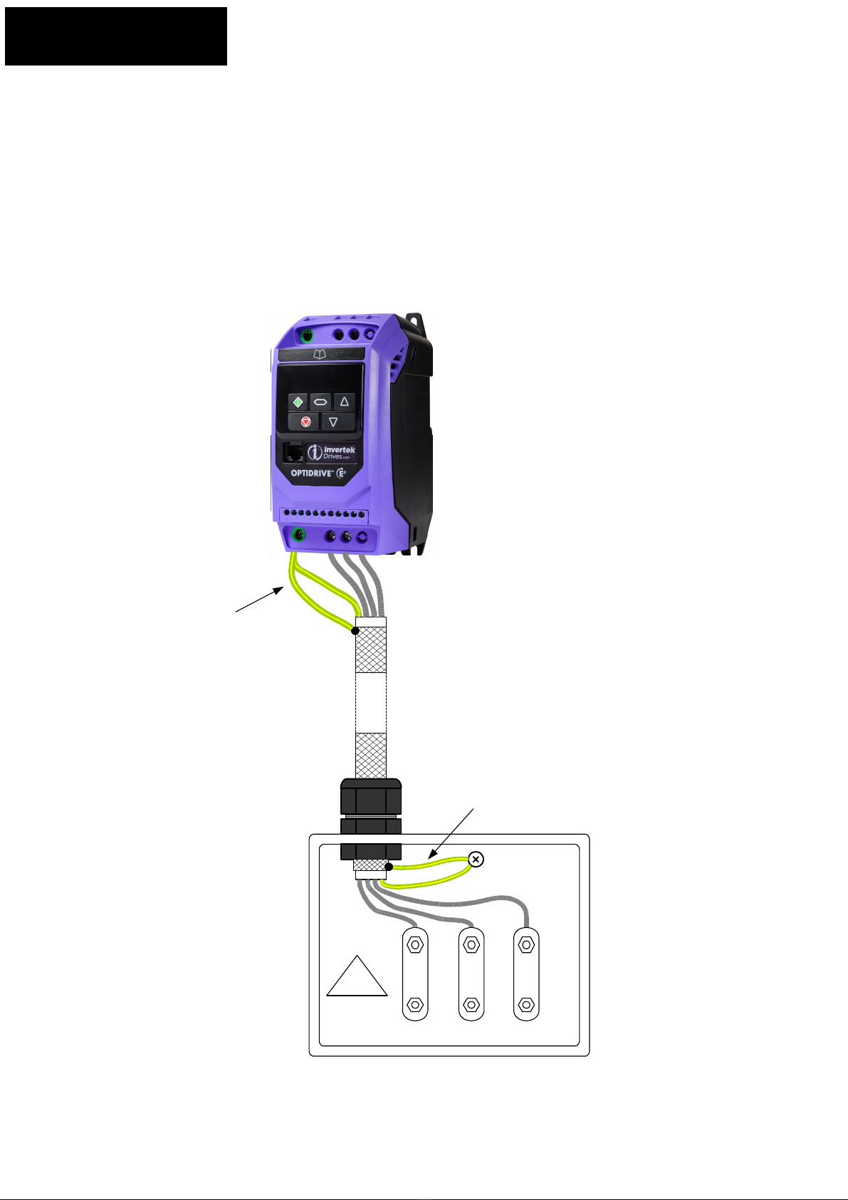
Basic EMC Information
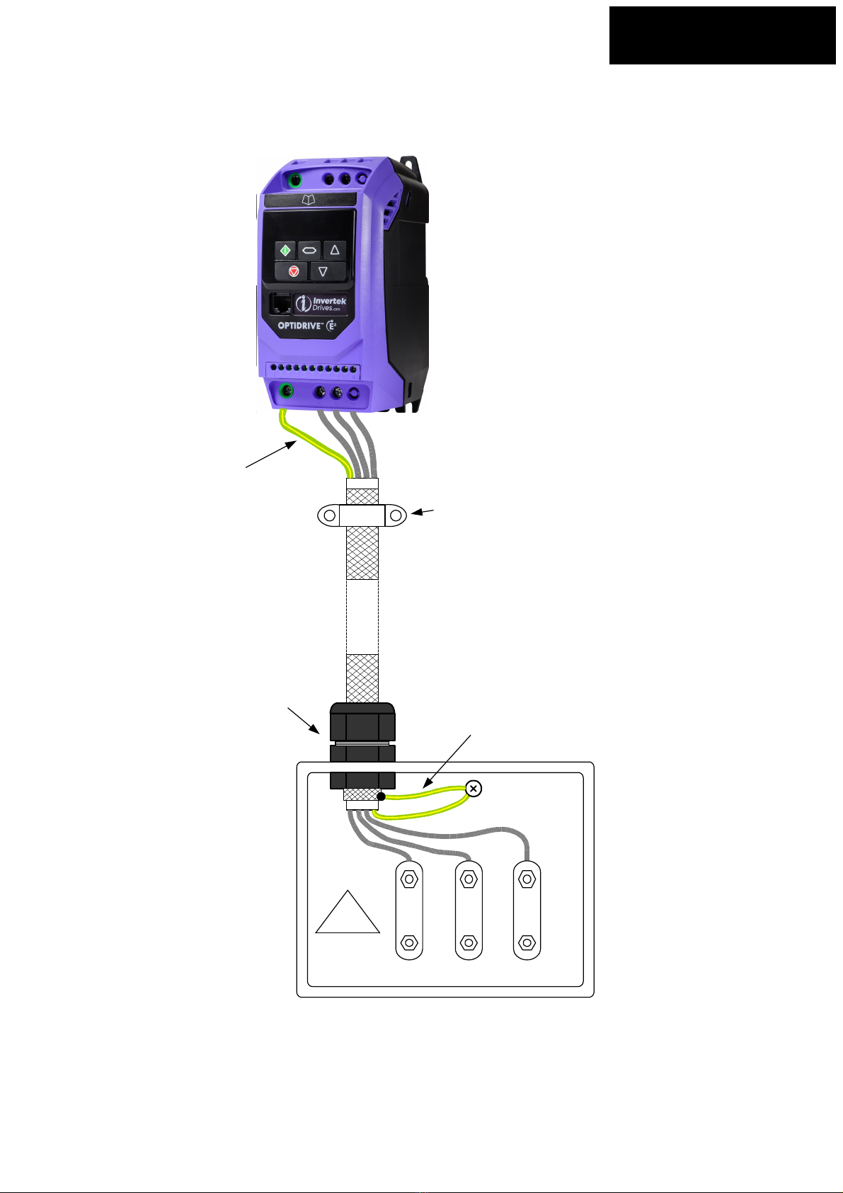
IP66 Power Wiring – Method 1
NOTE: Single phase input drive shown. Motor connections are the same for 3-phase drives.
L1/L L2/N L3 U V W
Mains
Supply
Cable
EMC
Motor
Cable
IP66 Nylon
Cable Gland
Motor Terminal
Box
Single
Phase
Supply
Motor
Terminals
U1 V1 W1
IP66 Nylon
Cable Gland
Keep earth tails as
short as possible
Keep earth tails as
short as possible
Cable screen to cover at
least 85% of the cable
surface area
Motor connected in DELTA
(Please check motor rating for correct connection)
IP66 Nylon
Cable Gland
Optidrive E3 Set-up Guide P a g e | 15
6
Basic EMC Information
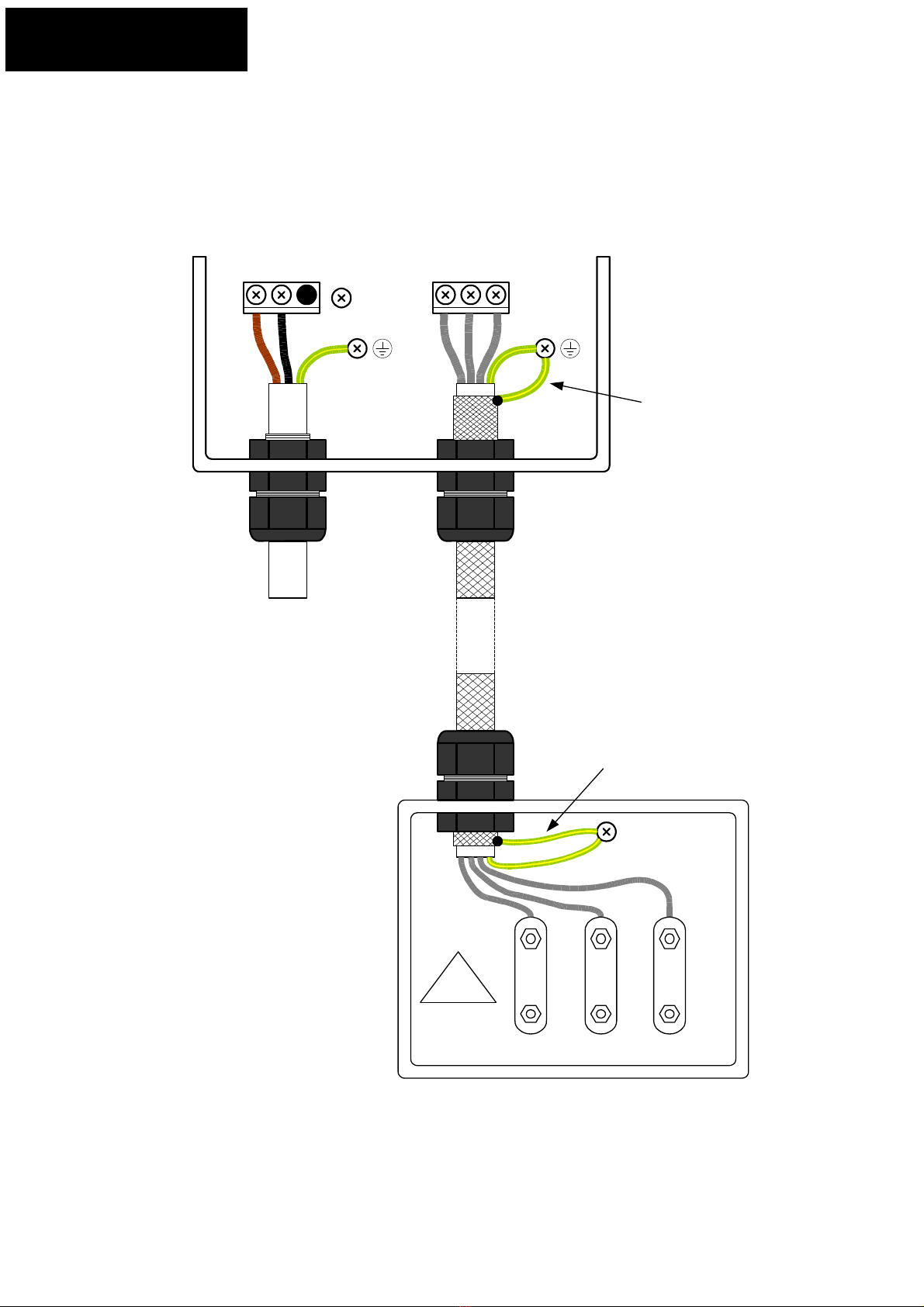
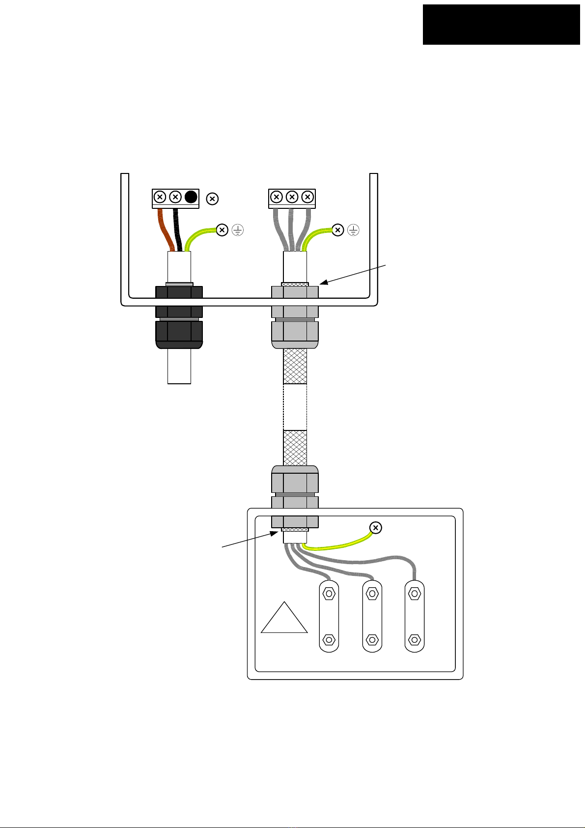
IP66 Power Wiring – Method 2
NOTE: Single phase input drive shown. Motor connections are the same for 3-phase drives.
L1/L L2/N L3 U V W
Mains
Supply
Cable
EMC
Motor
Cable
IP66 Nylon
Cable Gland
IP66 Metal
'EMC' Gland
Ensure EMC gland is fitted
correctly in accordance
with manufacturers
guidelines
IP66 Metal
'EMC' Gland
Ensure EMC gland is fitted
correctly in accordance
with manufacturers
guidelines
Motor Terminal
Box
Single
Phase
Supply
Motor
Terminals
Cable screen to cover at
least 85% of the cable
surface area

P a g e | 16 Optidrive E3 Set-up Guide
6
Basic EMC Information
Control Wiring
The following diagrams give examples of control wiring for good EMC performance
1 98765432 1110
+24V
DI 1
DI 2
DI 3 / AI 2
+10V
DI 4 / AI 1
0V
0V
DO 1 / AO 1
Status Relay
1 98765432 1110
DI 1
DI 2
DI 3 / AI 2
+10V
DI 4 / AI 1
0V
0V
DO 1 / AO 1
mA
+-
+24V
Status Relay
Optidrive E3 Set-up Guide P a g e | 17
6
Basic EMC Information
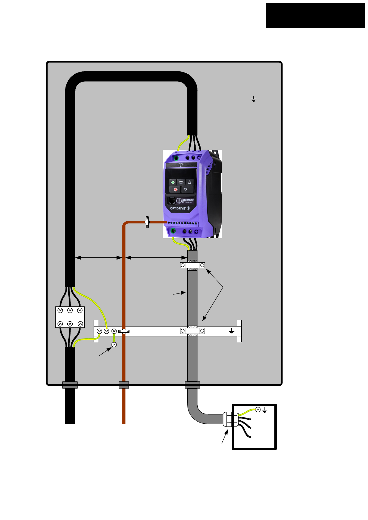
General requirements for good EMC practice
L1
L2
L3
Metal 'EMC' Gland
with cable shield/
screen connected to
gland as per
manufacturers
instructions
U
V
W
Mains Supply
Motor
terminal
box
Main earth busbar
Cable shield
exposed and
360
o
clamp
bonded to
metal backplate
or earth busbar
(Same for
control cables)
Motor Cable
3-phase and earth
shielded/screened
cable. Maintain
shield as far as
possible along cable
Control Cables
Twisted pair
shielded cables for
analogue signals
>100mm >100mm
Panel mounting
backplate with
conductive
surface
Metal backplate
bonded to main
earth busbar

P a g e | 18 Optidrive E3 Set-up Guide
6
Basic EMC Information
Braking resistor connections for good EMC practice
Cable shield
exposed and
360oclamp
bonded to
metal backplate
Panel mounting
backplate with
conductive
surface
Optional external
braking resistor
Optional external
braking resistor
Resistor thermal
overload protection
Resistor thermal
overload protection
Use screened cable if the
braking cable is leaving the
enclosure
Screened cable
Braking cable does not need
to be screened cable if not
leaving the enclosure. But
screened cable can be used
if so desired
Note: Some earth cables have been omitted for clarity. Please make sure braking resistor and case
are properly earthed.
This manual suits for next models
32
Table of contents
Popular DC Drive manuals by other brands


Danfoss
Danfoss VACON 3000 Application guide

Siemens
Siemens SINAMICS Equipment manual

KB Electronics
KB Electronics Penta Power KBRG-255 Installation and operating instructions

Santerno
Santerno SINUS H Series user manual

Digga
Digga PD Series Operator's manual

Omron
Omron SYSMAC CXONE-ALC-EV2 Series Operation manual


