manuals.online logo
Brands
  1. Home
  2. •
  3. Brands
  4. •
  5. Lenze
  6. •
  7. DC Drive
  8. •
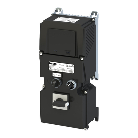
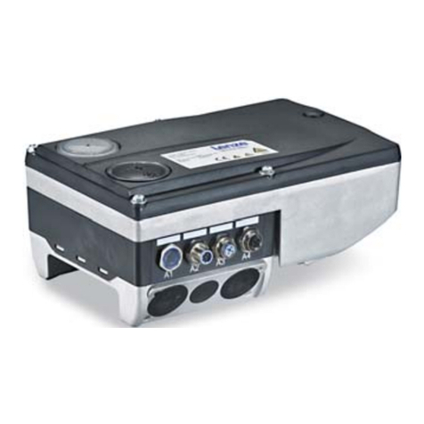
  9. Lenze 8200 motec User manual

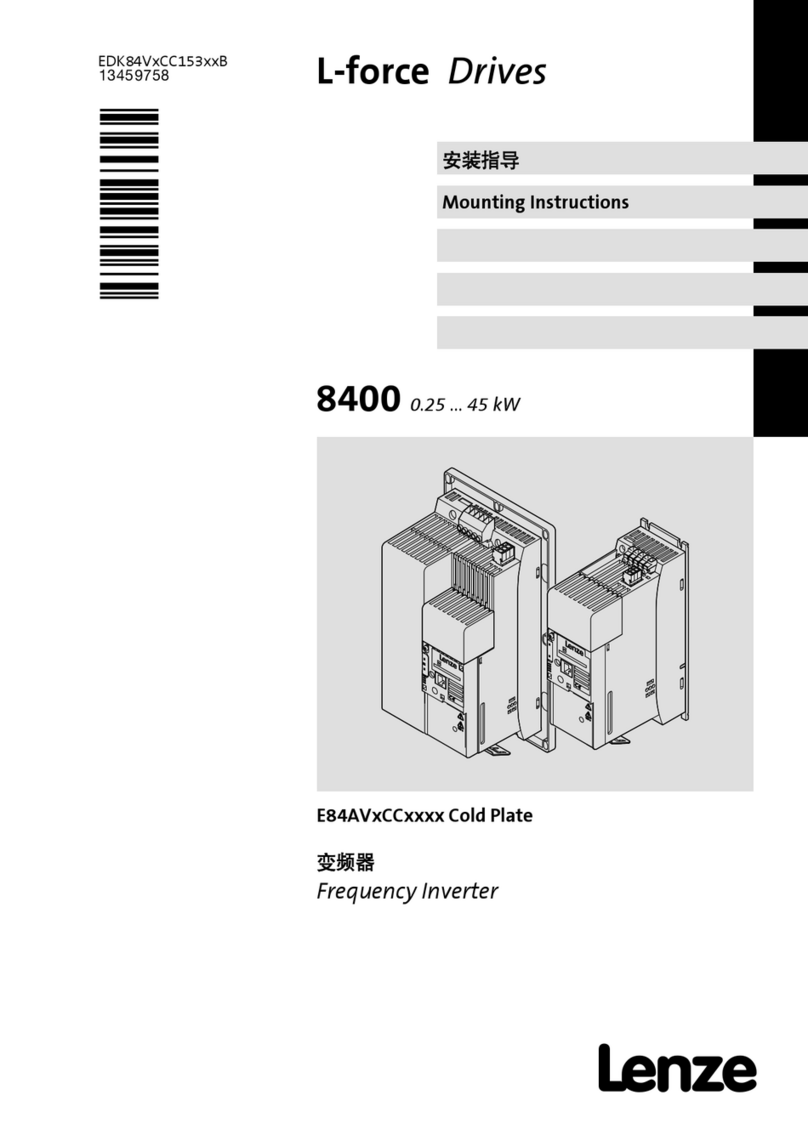
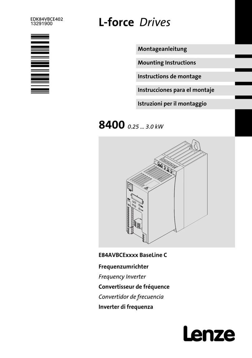
Lenze 8200 motec User manual

EDK82MV3
00403284
Montageanleitung
8200 motec
0.55 kW ... 2.2 kW
D
Mounting Instructions
GB
Instructions de montage
F
Show/Hide Bookmarks
Show/Hide Bookmarks
Manual
EDB82MVD- D
EDB82MVU- GB
EDB82 MVF- F
8200 motec
- E82MV551
- E82MV751
- E82MV152
- E82MV222
8200mot022/23
8200mot020/21
Der 8200 motec enthält elektrosta-
tisch gefährdete Bauelemente!
Vor Arbeiten imBereich der An-
schlüsse muß sich das Personal von
elektrostatischen Aufladungen be-
freien.
The 8200 motec contains
electrostatically endangered
components!
Before working on and with the
connections, the personnel must be
free of electrostatical charge.
Le 8200 motec comprend des
composants à décharges
électrostatiques !
Avant de procéder aux travaux sur
lesraccords,lespersonneseffec-
tuant ce travail devront se libérer des
décharges électrostatiques.
Show/Hide Bookmarks
EDM82MVDG 1. 0 D/ GB/ F 1

Sich erh eitsh inw eise Ant rieb sr eg ler
Sicherheits- und Anwendungshinweise für Antriebsstromrichter
(gemäß: Niederspannungsrichtlinie 73/23/EWG)
1. Allgemein
Während des Betriebes können Antriebsstromrichter ihrer Schutzart entsprechend spannungsführende, blanke, gegebenenfalls auch bewegliche oder rotierende
Teile, sowie heißeOberflächen besitzen.
Bei unzulässigem Entfernen der erforderlichen Abdeckung, bei unsachgemäßem Einsatz, bei falscher Installation oder Bedienung, besteht die Gefahr von
schweren Personen- oder Sachschäden.
Weitere Informationen sind der Dokumentation zu entnehmen.
Alle Arbeiten zum Transport, zur Installation und Inbetriebnahme sowie zur Instandhaltung sind von qualifiziertem Fachpersonal auszuführen (IEC 364 bzw.
CENELEC HD 384 oder DIN VDE 0100 und IEC-Report 664 oder DIN VDE 0110 und nationale Unfallverhütungsvorschriften beachten).
Qualifiziertes Fachpersonal im Sinne dieser grundsätzlichen Sicherheitshinweise sind Personen, die mit Aufstellung, Montage, Inbetriebsetzung und Betrieb des
Produktes vertraut sind und über die ihrer Tätigkeit entsprechenden Qualifikationen verfügen.
2. Bestimmungsgemäße Verwendung
Antriebsstromrichter sind Komponenten, die zum Einbau in elektrische Anlagen oder Maschinen bestimmt sind.
Bei Einbau in Maschinen ist die Inbetriebnahme der Antriebsstromrichter (d.h. die Aufnahme des bestimmungsgemäßen Betriebes) solange untersagt, bis
festgestellt wurde, daßdie Maschine den Bestimmungen der EG-Richtlinie 89/392/EWG (Maschinenrichtlinie) entspricht; EN 60204 ist zu beachten.
Die Inbetriebnahme (d.h. die Aufnahme des bestimmungsgemäßen Betriebes) ist nur bei Einhaltung der EMV-Richtlinie (89/336/EWG) erlaubt.
Die Antriebsstromrichter erfüllen die Anforderungen der Niederspannungsrichtlinie 73/23/EWG. Die harmonisierten Normen der Reihe EN 50178/DIN VDE 0160
in Verbindung mit EN 60439-1/DIN VDE 0660 Teil 500 und EN 60146/DIN VDE 0558 werden für die Antriebsstromrichter angewendet.
Die technischen Daten sowie die Angaben zu Anschlußbedingungen sind dem Leistungsschild und der Dokumentation zu entnehmen und unbedingt einzuhal-
ten.
3. Transport, Einlagerung
Die Hinweise für Transport, Lagerung und sachgemäße Handhabung sind zu beachten.
Klimatische Bedingungen sind entsprechend EN 50178 einzuhalten.
4. Aufstellung
Die Aufstellung und Kühlung der Geräte mußentsprechend den Vorschriften der zugehörigen Dokumentation erfolgen.
Die Antriebsstromrichter sind vor unzulässiger Beanspruchung zu schützen. Insbesondere dürfen bei Transport und Handhabung keine Bauelemente verbogen
und/oder Isolationsabstände verändert werden. Die Berührung elektronischer Bauelemente und Kontakte ist zu vermeiden.
Antriebsstromrichter enthalten elektrostatisch gefährdete Bauelemente, die leicht durch unsachgemäße Behandlung beschädigt werden können. Elektrische
Komponenten dürfen nicht mechanisch beschädigt oder zerstört werden (unter Umständen Gesundheitsgefährdung!).
5. Elektrischer Anschluß
Bei Arbeiten an unter Spannung stehenden Antriebsstromrichtern sind die geltenden nationalen Unfallverhütungsvorschriften (z.B. VBG 4) zu beachten.
Die elektrische Installation ist nach den einschlägigen Vorschriften durchzuführen (z.B. Leitungsquerschnitte, Absicherungen, Schutzleiteranbindung). Darüberhi-
nausgehende Hinweise sind in der Dokumentation enthalten.
Hinweise für die EMV-gerechte Installation - wie Schirmung, Erdung, Anordnung von Filtern und Verlegung der Leitungen - befinden sich in der Dokumentation
der Antriebsstromrichter. Diese Hinweise sind auch bei CE-gekennzeichneten Antriebsstromrichtern stets zu beachten. Die Einhaltung der durch dieEMV-Ge-
setzgebung geforderten Grenzwerte liegt in der Verantwortung des Herstellers der Anlage oder Maschine.
6. Betrieb
Anlagen, in die Antriebsstromrichter eingebaut sind, müssen ggf. mit zusätzlichen Überwachungs- und Schutzeinrichtungen gemäß den jeweils gültigen
Sicherheitsbestimmungen, z.B. Gesetz über technische Arbeitsmittel, Unfallverhütungsvorschriften usw. ausgerüstet werden. Veränderungen der Antriebsstrom-
richter mit der Bediensoftware sind gestattet.
Nach dem Trennen der Antriebsstromrichter von der Versorgungsspannung dürfen spannungsführende Geräteteile und Leistungsanschlüsse wegen möglicher-
weise aufgeladener Kondensatoren nicht sofort berührt werden. Hierzu sind die entsprechenden Hinweisschilder auf dem Antriebsstromrichter zu beachten.
Während des Betriebes sind alle Abdeckungen und Türengeschlossenzuhalten.
7. Wartung und Instandhaltung
Die Dokumentation des Herstellers ist zu beachten.
Diese Sicherheitshinweise sind aufzubewahren!
Show/Hide Bookmarks
2EDM82MVDG 1 .0 D/ GB/ F
Sich erh eitsh inw eise Dreh st rommas ch ine
Sicherheitshinweise für den Betrieb von Drehstrommaschinen
(gemäß: Niederspannungsrichtlinie 73/23/EWG)
1. Allgemein
Niederspannungsmaschinen haben gefährliche, spannungsführende und rotierende Teile sowie möglicherweise heißeOberflächen. Alle Arbeiten zum Transport,
Anschluß, zur Inbetriebnahme und Instandhaltung sind von qualifiziertem, verantwortlichem Fachpersonal auszuführen (prEN 50110-1/ VDE 0105; IEC 364
beachten). Unsachgemäßes Verhalten kann schwere Personen- und Sachschäden verursachen.
2. Bestimmungsgemäße Verwendung
Diese Niederspannungsmaschinen sind für gewerbliche Anlagen bestimmt. Sie entsprechen den harmonisierten Normen der Reihe
EN 60034 (VDE O53O). Der Einsatz im Ex-Bereich ist verboten, sofern nicht ausdrücklich hierfür vorgesehen (Zusatzhinweise beachten).
Schutzarten < IP 23 keinesfalls im Freien verwenden. Luftgekühlte Ausführungen sind für Umgebungstemperaturen von -205C bis + 405C sowie Aufstellungs-
höhen < 1000 m über NN bemessen. Abweichende Angaben auf dem Leistungsschild unbedingt beachten. Die Bedingungen am Einsatzort müssen allen
Leistungsschildangaben entsprechen.
Niederspannungsmaschinen sind Komponenten zum Einbau in Maschinen im Sinne der Maschinenrichtlinie 89/392/EWG.Die Inbetriebnahme ist solange
untersagt, bis die Konformität des Endproduktes mit dieser Richtlinie festgestellt ist (u.a. EN 60204-1 beachten).
3. Transport, Einlagerung
Nach der Auslieferung festgestellte Beschädigungen dem Transportunternehmen sofort mitteilen; die Inbetriebnahme ist ggf. auszuschließen. Eingeschraubte
Transportösen fest anziehen. Sie sind für das Gewicht der Niederspannungsmaschine ausgelegt, keine zusätzlichen Lasten anbringen. Wenn notwendig geei-
gnete, ausreichend bemessene Transportmittel (z.B.Seilführungen) verwenden.
Vorhandene Transportsicherungen vor Inbetriebnahme entfernen. Für weitere Transporte erneut verwenden. Werden Niederspannungsmaschinen eingelagert,
auf eine trockene, staubfreie und schwingungsarme (v eff < O,2mm/s) Umgebung achten (Lagerstillstandsschäden). Vor Inbetriebnahme Isolationswiderstand
messen. Bei Werten < 1k je Volt Bemessungsspannung Wicklung trocknen.
4. Aufstellung
Auf gleichmäßige Auflage, gute Fuß-bzw.Flanschbefestigung und genaue Ausrichtung bei direkter Kupplung achten. Aufbaubedingte Resonanzen mit der
Drehfrequenz und der doppelten Netzfrequenz vermeiden. Läufer von Hand drehen, auf ungewöhnliche Schleifgeräusche achten. Drehrichtung im ungekuppel-
ten Zustand kontrollieren (Abschn. 5 beachten).
Riemenscheiben und Kupplungen nur mit geeigneten Vorrichtungen auf- bzw. abziehen (Erwärmen!) und mit einem Berührungsschutz abdecken. Unzulässige
Riemenspannungen vermeiden (Techn.Liste).
Der Wuchtzustand der Niederspannungsmaschine ist auf dem Wellenspiegel oder Leistungsschild angegeben (H = halbe-,F = ganze Paßfeder). Bei Ausführung
mit halber Paßfeder (H) mußdie Kupplung ebenfalls mit halber Paßfeder gewuchtet sein. Überstehenden, sichtbaren Paßfederanteil abarbeiten.
Eventuell erforderliche Rohranschlüsse herstellen. Bauformen mit Wellenende nach oben bauseits mit einer Abdeckung ausrüsten, die das Hineinfallen von
FremdkörpernindenLüfter verhindert. Die Belüftung darf nicht behindert und die Abluft - auch benachbarter Aggregate - nicht unmittelbar wieder angesaugt
werden.
5. Elektrischer Anschluß
Alle Arbeiten dürfen nur von qualifiziertem Fachpersonal an der stillstehenden Niederspannungsmaschine im freigeschalteten und gegen Wiedereinschalten
gesicherten Zustand vorgenommen werden. Dies gilt auch für Hilfsstromkreise (z.B. Stillstandsheizung).
Spannungsfreiheit prüfen!
Überschreiten der Toleranzen in EN 60034-1 (VDE 0530,Teil1)- Spannung + 5%, Frequenz + 2%, Kurvenform, Symmetrie - erhöht die Erwärmung und
beeinflußt die elektromagnetische Verträglichkeit. Leistungsschildangaben sowie das Anschlußschema im Anschlußkasten beachten.
Schaltungs-und abweichende Angaben auf dem Leistungsschild sowie das Anschlußschema im Anschlußkasten beachten.
Der Anschlußmußso erfolgen, daßeine dauerhaft sichere, elektrische Verbindung aufrecht erhalten wird (keine abstehenden Drahtenden); zugeordnete
Kabelendbestückung verwenden. Sichere Schutzleiterverbindung herstellen.
Die kleinsten Luftabstände zwischen blanken, spannungsführenden Teilen untereinander und gegen Erde dürfen folgende Werte nicht unterschreiten: 8mm bei
UN < 550V, 10mm bei UN <725V, 14mm bei UN <1000V.
Im Anschlußkasten dürfen sich keine Fremdkörper, Schmutz sowie Feuchtigkeit befinden. Nicht benötigte Kabeleinführungsöffnungen und den Kasten selbst
staub- und wasserdicht verschließen. Für den Probebetrieb ohne Abtriebselemente Paßfeder sichern. Bei Niederspannungsmaschinen mit Bremse vor der
Inbetriebnahme die einwandfreie Funktion der Bremse prüfen.
6. Betrieb
Schwingstärken v eff < 3,5 mm/s (PN < 15 kW) bzw.4,5mm/s (PN > 15 kW) im gekuppelten Betrieb sind unbedenklich. Bei Veränderungen gegenüber dem
Normalbetrieb z.B. erhöhte Temperaturen, Geräusche, Schwingungen Ursache ermitteln, eventuell Rücksprache mit dem Hersteller. Schutzeinrichtungen auch
im Probebetrieb nicht außer Funktion setzen. Im Zweifelsfall Niederspannungsmaschine abschalten.
Bei starkemSchmutzanfall Luftwege regelmäßig reinigen.
Lagerungen mit Nachschmiereinrichtung bei laufender Niederspannungsmaschine nachfetten. Verseifungsart beachten. Falls Fettaustrittsbohrungen mit Stopfen
verschlossen sind (IP54 Abtriebsseite; IP23 Abtriebs-und Nichtabtriebsseite), vor Inbetriebnahme Stopfen entfernen. Bohrungen mit Fett verschließen. Lager-
wechsel bei Dauerschmierung (2Z-Lager) nach ca. 10.000 Std. (2pol.) bzw. 20.000 Std.(höherpolig), spätestens jedoch nach 3-4 Jahren oder nach Herstelle-
rangaben.
Show/Hide Bookmarks
EDM82MVDG 1 .0 D/ GB/ F 3

Safety and Operating Instructions for Controllers
(in conformity with the Low-Voltage Directive 73/23/EEC)
Safet y Ins tr uc tions c ont rollers
1. General
In operation, drive converters, depending on their degree of protection, may have live, uninsulated, and possibly also moving or rotating parts, as well as hot
surfaces.
In case of inadmissible removal of the required covers, of improper use, wrong installation or maloperation, there is the danger of serious personal injury and
damage to property.
For further information, see documentation.
All operations serving transport, installation and commissioninng as well as maintenance are to be carried out by skilled technical personnel (Observe IEC 364
or CENELEC HD 384 or DIN VDE 0100 and IEC 664 or DIN/VDE 0110 and national accident prevention rules!).
For the purposes of these basic safety instructions, ”skilled technical personnel”means persons who are familiar with the installation, mounting, commissioning
and operation of the product and have the qualifications needed for the performance of their functions.
2. Intended use
Drive converters are components designed for inclusion in electrical installations or machinery.
In case of installation in machinery, commissioning of the drive converter (i.e. the starting of normal operation) is prohibited until the machinery has been proved
to conformto the provisions of the directive 89/392/EEC (Machinery Safety Directive - MSD). Account is to be taken of EN 60204.
Commissioning (i.e. the starting of normal opertion) is admissible only where conformity with the EMC directive (89/336/EEC) has been established.
The drive converters meet the requirements of the low-voltage directive 73/23/EEC. They are subject to the harmonized standards of the series prEN 50178/DIN
VDE 0160 in conjunction with EN 60439-1/ VDE 0660, part 500, and EN 60146/ VDE 0558.
The technical data as well as information concerning the supply conditions shall be taken from the rating plate and from the documentation and shall be strictly
observed.
3. Transport, storage
The instructions for transport, storage and proper use shall be complied with.
The climatic conditions shall be in conformity with EN 50178.
4. Installation
The installation and cooling of the appliances shall be in accordance with the specifications in the pertinent documentation.
The drive converters shall be protected against excessive strains. In particular, no components must be bent or isolating distances altered in the course of
transportation or handling. No contact shall be made with electronic components and contacts.
Drive converters contain electrostatic sensitive components which are liable to damage through improper use. Electric components must not be mechanically
damaged or destroyed (potential health risks).
5. Electrical connection
When working on live drive converters, the applicable national accident prevention rules (e.g. VBG 4) must be complied with.
The electrical installation shall be carried out in accordance with the relevant requirements (e.g. cross-sectional areas of conductors, fusing, PE connection). For
further information, see documentation.
Instructions for the installation in accordance with EMC requirements, like screening, earthing, location of filters and wiring, are contained in the drive converter
documentation. They must always be complied with, also for drive converters bearing a CE marking. Observance of the limit values required by EMC law is the
responsibility of the manufacturer of the installation or machine.
6. Operation
Installations which include drive converters shall be equipped with additional control and protective devices in accordance with the relevant applicable safety
requirements, e.g. Act respecting technical equipment, accident prevention rules etc. Changes to the drive converters by means of the operating software are
admissible.
After disconnection of the drive converter from the voltage supply, live appliance parts and power terminals must not be touched immediately because of
possibly energized capacitors. In this respect, the corresponding signs and markings on the drive converter must be respected.
During operation, all covers and doors shall be kept closed.
7. Maintenance and servicing
The manufacturer’s documentation shall be followed.
Keep safety instructions in a safe place!
Show/Hide Bookmarks
4EDM82MVDG 1 .0 D/ GB/ F
Safety and Operating Instructions for three-phase AC machines
(in confirmity with LOW-Voltage Directive 73/23/EEC)
Safety Instructions three–phase AC machines
1. General
Low-voltage machines have dangerous live and rotating parts and possibly hot surfaces. All operations serving transport, connection, commissioning and
maintenance are to be carried out by skilled, responsible technical personnel (in conformity with prEN 50110-1/ VDE 0105; IEC 364). Improper handling may
cause serious personal injury and damage to property.
2. Intended use
These low-voltage machines are intended for industrial and commercial installations. They comply with the harmonized series of standards EN 60034 (VDE
O53O). Their use in hazardous areas is prohibited unless they are expressly intended for such use (follow additional instructions). The degrees of protection IP
23 are by nomeans intended for outdoor use. Air-cooled models are rated for ambient temperatures of - 205C to + 405C and altitudes of 1000 m above sea
level. Strictly observe different instructions on the rating plate. Conditions on site must conform to all rating plate markings.
Low-voltage machines are components for installation in machinery as defined in the Machinery Directive 89/392/EEC. Commissioning is prohibited until
conformity of the end product with this directive has been established. (Follow i.a. EN 60204-1).
3 Transport, storage
Immediately report damage established after delivery to transport company. Stop commissioning, if necessary. Tighten screwed-in ring bolts before transport.
They are designed for the weight of the low-voltage machine, do not apply extra loads. If necessary, use suitable, adequately dimensioned means of transport
(e.g. rope guides). Remove shipping brace before commissioning. Reuse it for further transports. When low-voltage machines are stored, make sure of dry,
dust-free, low-vibration (Vrms 0.2 mm/s)environment (danger of bearing damage at rest). Before commissioning, measure insulation resistance. In case of
values 1 k per volt of rated voltage, dry winding.
4. Installation
Make sure of even supporting surface, solid foot or flange mounting and exact alignment in case of direct coupling. Avoid resonances with rotational frequency
and double mains frequency which may be caused by the assembly. Turn motor by hand, listen for abnormal slipping noises. Check direction of rotation in
uncoupled state (mind Section 5.)
Mount or remove belt pulleys and couplings only using appropriate means (heat!) and cover them with a touch guard. Avoid excessive belt tensions (technical
list).
The balance of the low-voltage machine is indicated on the shaft end face or on the rating plate (H = half, F = full key). In case of half-key design, the coupling,
too, must be half-key balanced.
Remove protruding, visible part of key. Make necessary ventilating pipe connections, if any. Models with shaft ends pointing upward are to be providedwitha
cover by the customer to prevent foreign objects from falling into the ventilator. The ventilation must not be obstructed and the exhaust air, also of neighbouring
sets, must not be drawn in again directly.
5. Electrical connection
All operations may be carried out only by skilled technical personnel on the low-voltage machine at rest and de-energized and provided with a safeguardto
prevent unintentional reclosing. This also applies to auxiliary circuits (e.g. anti-condensation heating).
Check safe isolation from supply!
Exceeding of the tolerances specified EN 60034-1 (VDE 0530,Teil1), i.e. voltage + 5%, frequency + 2%, waveform, symmetry, leads to elevated temperatures
and affects the electromagnetic compatibility. Take account of rating plate markings and of connection diagram in terminal box.
The connection must be so made as to mainntain a permanent safe electrical connection (no loose wire ends). Use appropriate cable terminals. Establishsafe
protective conductor connection.
Minimumclearances between uninsulated live parts and between such parts and earth must not be below the following values: 8 mm at UN550 V, 10 mm at
UN725 V, 14 mm at UN1000 V. No presence of foreign objects, dirt or moisture is admitted in the terminal box. Close unused cable entrance holes and the box
itself in a dust- and watertight manner. For trial run without output elements, lock key. For low-voltage machines with brakes, check satisfactory functioning of
brake before commissioning.
6. Operation
Vibration severities of Vrms 3.5 mm/s (PN15 kW) or 4.5 mm/s (PN> 15 kW) are acceptable in coupled-mode operation. In case of deviations from normal
operation - e.g. elevated temperatures, noises, vibrations - find cause or consult manufacturer, if necessary. Do not defeat protective devices, noteveninatrial
run. If in doubt, switch off low-voltage machine. In case of heavy dirt deposits, clean air channels periodically.
Regrease bearings with relubricating device while the low-voltage machine is running. Use right kind of grease. Where grease exit holes are closed with plugs
(IP 54 drive end, IP 23 drive and non-drive ends), remove plug before commissioning. Seal holes with grease. Replace prelubricated bearings (2-Z bearings)
after abt. 10,000 hours (2-poles) or after 20,000 hours (>2-poles), but no later than after three to four years or according to the manufacturer’s instructions.
Show/Hide Bookmarks
EDM82MVDG 1 .0 D/ GB/ F 5

Consignes de sécurité- Convertisseurs de fréquence
Instructions de sécuritéet d’emploi relatives aux convertisseurs d’entraînement
(conformes àla directive Basse Tension 73/23/CEE)
1. Généralités
Selon leur degréde protection, les convertisseurs d’entraînement peuvent comporter, pendant leur fonctionnement, des parties nues sous tension, éventuelle-
ment en mouvement ou tournantes, ainsi que des surfaces chaudes.
L’enlèvement non admis de recouvrements préscrits, l’usage non conforme àla destination, une installation défectueuse ou une manoeuvre erronéepeuvent
entraîner des dangers de dommages corporels et matériels graves.
Pour informations complémentaires, consulter la documentation.
Tous travaux relatifs au transport, àl’installation, àla mise en service et àla maintenance doivent être exécutées par du personnel qualifiéet habilité(voir CEI
364 ou CENELEC HD 384, ou DIN VDE 100 et CEI664 ou DIN/VDE 0110, ainsi que les prescriptions de prévention d’accidents nationales).
Au sens des présentes instructions de sécuritéfondamentales, on entend par personnel qualifiédes personnes compétentes en matière d’installation, de
montage, de mise en service et de fonctionnement du produit et possédant les qualifications correspondant àleurs activités.
2. Utilisation conforme àla destination
Les convertisseurs d’entraînement sont des composants destinésàêtre incorporés dans des installations ou machines électriques.
En cas d’incorporation dans une machine, leur mise en service (c’est-à-dire leur mise en fonctionnement conformément àleur destination) est interdite tant que
la conformitéde la machine avec les dispositions de la Directive 89/392/CEE (directive sur les machines)n’apasétévérifiée; respecter la norme EN 60024.
Leur mise en service (c’est-à-dire leur mise en fonctionnement conformément àleur destination) n’est admise que si les dipositions de la Directive sur la
compatibilitéélectromagnétique (89/336/CEE) sont respectées.
Les convertisseurs d’entraînement répondent aux exigences de la Directive Basse Tension 73/23/CEE. Les normes harmonisées de la série prEN 50178/DIN
VDE 0160 en connexion avec la norme EN 60439-1/ VDE 0660, partie 500 et EN 60146/ VDE 0558 leur sont applicables.
Les caractéristiques techniques et les indications relatives aux conditions de raccordement selon la plaque signalétique et la documentation doivent obligatoire-
ment être respectées.
3. Transport, stockage
Les indications relatives au transport, au stockage et au maniement correct doivent être respectées.
Les conditions climatiques selon la EN 50178 doivent être respectées.
4. Installation
L’installation et le refroidissement des appareils doivent répondre aux prescriptions de la documentation fournie avec le produit.
Les convertisseurs d’entraînement doivent être protégés contre toute contrainte inadmissible. En particuier, il ne doit y avoir déformation de pièces et/ou
modification des distances d’isolement des composants lors du transport et de la manutention. Il doit être évitéde toucher les composants électroniques et
pièces de contact.
Les convertisseurs d’entraînement comportent des pièces sensibles aux contraintes électrostatiques et facilement endommageables par un maniement in-
adéquat. Les composants électriques ne doivent pas être endommagésoudétruits mécaniquement (le cas échéant, risques pour la santé!)
5. Raccordement électrique
Lorsque des travaux sont effectués sur le convertisseur d’entraînement sous tension, les prescriptions pour la prévention d’accidents nationales doivent être
respectées (par exemple VBG 4).
L’installation électrique doit être exécutéeenconformitéavec les prescriptions applicables (par exemple sections des conducteurs, protection par coupe-circuit
àfusibles, raccordement du conducteur de protection). Des renseignements plus détaillés figurent dans la documentation.
Les indications concernant une installation satisfaisant aux exigences de compatibilitéélectromagnétique, tels que blindage, mise àla terre, présencedefiltres
et pose adéquate des câbles et conducteurs) figurent dans la documentation qui accompagne les convertisseurs d’entraînement. Ces indications doivent être
respectées dans tous les cas, même lorsque le convertisseur d’entraînement porte le marquage CE. Le respect des valeurs limites imposées par la législation
sur la CEM relève de la responsabilitédu constructeur de l’installation ou de la machine.
6. Fonctionnement
Les installations dans lesquelles sont incorporés des convertisseurs d’entraînement doivent être équipées des dispositifs de protection et de surveillance
supplémentaires prévus par les prescriptions de sécuritéen vigueur qui s’y appliquent, telles que la loi sur le matériel technique, les prescriptions pour la
prévention d’accidents, etc. Des modifications des convertisseurs d’entraînement au moyen du logiciel de commande sont admises.
Aprèslaséparation du convertisseur de l’alimentation, les parties actives de l’appareil et les raccordements de puissance sous tension ne doivent pas être
touchésimmédiatement, en raison de condensateurs éventuellement chargés. Respecter àcet effet les pancartes d’avertissement fixées sur les convertisseurs
d’entraînement.
Pendant le fonctionnement, tous les portes et recouvrements doivent être maintenus fermés.
7. Entretien et maintenance
La documentation du constructeur doit être prise en considération.
Conserver ces instructions de securite!
Show/Hide Bookmarks
6EDM82MVDG 1 .0 D/ GB/ F
Instructions de sécuritépour l’utisilation de machines àcourant triphasé
(Conformes àla directive Basse Tension 73/23/CEE)
Consignes de sécurité- Machines àcourant triphasé
1. Généralités
Les machines BT comportent des parties dangéreuses sous tension et tournantes, ainsi que, le cas échéant, des surfaces chaudes. L’ensemble des opérations
relatives au transport, au raccordement, àla mise en service et àla maintenance doivent être exécutées par du personnel qualifiéhabilitéet responsable (voir
prEN 50110-1/ VDE 0105; IEC 364). Tout comportement ou maniement inappropriéest susceptible de causer des dommages corporels et matériels graves.
2. Utilisation conforme àla destination
Ces machines BT sont destinées àêtre utilisées dans des installations industrielles et commerciales. Elles répondent aux normes harmonisées de la série EN
60034 (VDE O53O). Leur utilisation dans des atmosphères explosives est interdite, àmoins qu’elles ne soient expressément prévues àcet effet (respecter les
indications supplémentaires). Les machines de degréde protection inférieur ou égal àIP 23 ne doivent en aucun cas être utilisées àl’extérieur. Les machines à
refroidissement par air sont conçues pour des températures ambiantes de -205C à+ 405C et des altitudes inférieures ou égales à1000 m au-dessus du niveau
de la mer. D’éventuelles indications divergentes sur la plaque signalétique doivent être impérativement respectées. Les conditions sur le site doivent correspon-
dre àla totalitédes indications de la plaque signalétique.
Les machines BT sont des composants destinésàêtre incorporés dans des machines au sens de la directive sur les machines 89/392/CEE. Leur mise en
service est interdite tant que la conformitédu produit final avec cette directive n’apasétéétablie (respecter e.a. la norme EN 60204-1).
3. Transport, stockage
D’éventuels dommages constatésaprès la livraison doivent être signalésimmédiatement àl’entreprise de transport; si nécessaire, la mise en service doit être
annulée. Les oeillets de transport vissésdoiventêtre bien serrés. Ils sont dimensionnésenfonctiondupoidsdelamachineBT;parconséquent, aucune charge
supplémentaire ne doit leur être appliquée. En cas de besoin, utiliser des moyens auxiliaires de transport appropriésdedimensionsadéquates (par exemple
guidage par câbles).
Avant la mise en service, enlever les arrêts de transport. Les réutiliser pour d’autres opérations de transport. Lorsque des machines BT sont entreposées, veiller
àce que l’environnement soit sec, exempt de poussières et, dans la mesure du possible, de vibrations (Veff 0,2 mm/s). Danger d’endommagement des paliers
suite àl’arrêtprolongédes machines! Avant la mise en service, mesurer la résistance d’isolement. En cas de valeurs mesurées inférieures ou égales à1kpar
volt de tension assignée, sécher les enroulements.
4. Installation
Veiller àune surface d’appui plane, une bonne fixation des pieds ou, selon le cas, des brides, et àun alignement précis en cas d’accouplement direct. Eviter
que le montage ne soit àl’origine de résonances avec la fréquencederotationetledoubledelafréquence du réseau. Faire tourner le rotor manuellement pour
détecter d’éventuels bruits de frottement anormaux. Contrôlerlesensderotationàl’état non couplé(tenir compte de ce qui est dit sous 5).
Ne monter et démonter les poulies et accouplements qu’à l’aide de dispositifs appropriés(chauffés!) et les protéger contre les contacts par un recouvrement
adéquat. Eviter des tensions de courroie inadmissibles (liste technique).
L’équilibrage de la machine BT est indiquésurlafaceduboutd’arbre ou la plaque signalétique (H = demi-clavette, F = clavette entière). En cas d’équilibrage
par demi-clavette, l’équilibrage de l’accouplement doit également se faire par demi-clavette. Enlever la partie visible et faisant saillie de la clavette.
Le cas échéant, réaliser les raccords de conduits nécessaires aux canalisations d’air. Les modèles avec bout d’arbre dirigévers le haut doivent être recouverts,
lors du montage, pour empêcher la chute de corps étrangers dans le ventilateur. La ventilation ne doit pas être entravée; l’air d’évacuationdelamachine-de
même que celui de groupes voisins - ne doit pas être directement aspiré.
5. Raccordement électrique
Les travaux ne doivent être effectués que par du personnel qualifiéhabilité, la machine étant au repos, séparéedel’alimentation et protégéecontretout
réenclenchement intempestif. Ceci vaut également pour les circuits auxiliaires (par exemple chauffage àl’arrêt). Vérifier l’absencedetension!
Tout dépassement des tolérances selon la EN 60034-1/ VDE 0530,Teil1 (tension + 5%, fréquence + 2 %, forme et symétrie des tensions et courants) a pour
effet une augmentation de l’échauffement et influe sur la compatibilitéélectromagnétique. Respecter les indications de la plaque signalétique ainsi que le
schéma de raccordement dans la boîte de connexion.
Le raccordement doit être réaliséde manière àassurer une liaison électrique durable et sûre (pas de brins effilochés!); utiliser les embout prévus àcet effet.
Réaliser une connexion du conducteur de protection sûre.
Les distances dans l’air minimales entre les parties nues sous tension et entre celles-ci et la terre ne doivent pas être inférieures aux valeurs suivantes: 8 mm à
UN550 V, 10 mm àUN725 V, 14 mm àUN1000 V.
La boîte de connexions ne doit contenir ni corps étrangers, ni saletés ou humidité. Les entrées de câbles non utiliséedoiventêtre obturées, la boîte elle-même
devant être ferméedefaçon àêtre étanche àl’eau et àla poussière. Pour l’essaidemiseenmarchesanséléments entraînants, veiller àce que la clavette soit
immobilisée. Dans le cas des machines BT munies de freins, vérifier le bon état de fonctionnement du frein avant la mise en service de la machine.
6. Fonctionnement
DesvibrationsdevitesseV
eff 3,5 mm/s (PN15 kW) ou 4,5 mm/s (PN> 15kW) respectivement en marche couplésont sans conséquence. En cas de déviation
par rapport au fonctionnement normal - par exemple températures élevées, bruit, vibrations - en rechercher l’origine. Le cas échéant, consulter le constructeur.
Les dispositifs de protection ne doivent pas être mis hors d’état de fonctionner même lors de l’essaidemiseenmarche.Encasdedoute,déconnecter la
machine BT. En présence de poussières abondantes, nettoyer régulièrement les canalisations de ventilation.
Les paliers àdispositif de regraissage doivent être regraissés lorsque la machine BT est en marche. Faire attention àla nature du lubrifiant! Au cas oùles trous
de sortie de graisse seraient obturéspardesbouchons(IP54ducôtéentraînement, IP 23 des côtésentraînement et opposéàl’entraînement), enlever les
bouchons avant la mise en service. Fermer les trous àl’aide de graisse. Les paliers àlubrification permanente (paliers 2Z) doivent être changésaprèsenviron
10.000 heures (2- pôles) ou 20.000 heures (àplus de deux pôles), mais au plus tard après3ou4années, ou encore suivant les indications du constructeur.
Show/Hide Bookmarks
Technische Daten
Technical Data
Spécifications techniques
EDM82MVDG 1 .0 D/ GB/ F 7

Temperaturbereiche Transport -255C0 +705C
T
e
m
p
e
r
a
t
u
r
b
e
r
e
i
c
h
e
Temperature ranges Lagerung Storage Stockage -255C0 +605C
T
e
m
p
e
r
a
t
u
r
e
r
a
n
g
e
s
P
la
g
es de tem
p
érature Betrieb Operation Service -205C0 +405C; +405C0 +605C(2,5%/K)
PG-Verschraubungen Ge
w
indelänge 10
m
m
; Gegen
m
u
t
t
e
r
nau
s
M
e
t
all
P
G
V
e
r
s
c
h
r
a
u
b
u
n
g
e
n
PG glands
G
e
w
i
n
d
e
l
ä
n
g
e
1
0
m
m
;
G
e
g
e
n
m
u
t
t
e
r
n
a
u
s
M
e
t
a
l
l
Thread length 10 mm; metal counter nuts 2xPG16 2xPG13,5 2xPG11 2xPG9
P
G
g
l
a
n
d
s
R
accords vissés
P
G
T
h
r
e
a
d
l
e
n
g
t
h
1
0
m
m
;
m
e
t
a
l
c
o
u
n
t
e
r
n
u
t
s
Longueur filetée10mm;contre-écrous en métal
2
x
P
G
1
6
2
x
P
G
1
3
,
5
2
x
P
G
1
1
2
x
P
G
9
Schutzart
Type of protection
Protection
IP55; NEMA 1: Berührschutz
IP55; NEMA 1: Protection against contact
IP55; NEMA 1 : Protection contre les contacts accidentels
Einbaufreiraum
Assembly space
Espace de montage
≥100 mm oberhalb und seitlich
≥100mmaboveandatthesides
≥100 mm au-dessus et de chaque côtéde l’appareil
E82MV551 E82MV751 E82MV152 E82MV222
U
L
1
L
2
L
3
150 % Überlast
150 % overload
150 % de surcharge de courant
320 V - 0% ... 550 V + 0 %; 48 Hz - 0 % 0 62 Hz + 0%
U
L1,L2,L3 120 % Überlast
120 % overload
120 % de surcharge de courant
320 V- 0% ... 440 V + 0 %; 48 Hz - 0 % ... 62 Hz + 0%
IL1,L2,L3 1.7 A 2.4 A 3.8 A 5.5 A
Gewicht (nur motec)
Weight (motec only)
Poids (motec unique-
ment)
2.8 kg 2.8 kg 4.1 kg 4.1 kg
b
ad
c
e
f
a[mm] b[mm] c[mm] d[mm] e[mm] f[mm]
E82MV551 156.00 151.25 132.00 202.00 16.25 25.50
E82MV751 156.00 151.25 132.00 202.00 16.25 25.50
E82MV152 176.00 167.25 148.00 230.00 14.25 25.50
E82MV222 176.00 167.25 148.00 230.00 14.25 25.50
Show/Hide Bookmarks
motec mit Motor oder Getriebemotor
motec with motor or geared motor
motec avec moteur ou motoréducteur
8EDM82MVDG 1 .0 D/ GB/ F
8200mot002
15
Show/Hide Bookmarks
Lieferumfang (Wand- / Motormontage)
Packing list (wall / motor mounting)
Equipement livré(montage au mur / sur le moteur)
EDM82MVDG 1.0 D/ GB/ F 9

1a
2a
2x
4a
4b
4x
X1
1b
3
X2
M4x25
8200mot003
1a Trägergehäuse Carrier housing Support
1b Elektronikmodul Electronics module Module électronique
2a Dichtung Gasket Joint
3Distanz- und Wandplatte Distance and wall-mounting plate Plaque de montage au mur
4a Verschlußplatte Wandmontage Cover plate for wall mounting Capot d’obturation pour montage au
mur
4b Schrauben Wandmontage Screws for wall mounting Vis pour montage au mur
X1 Klemmleiste Netzanschluß, Relais,
Bremswiderstand Terminal strip mains connection, relay
brake resistor Bornier raccordement réseau, relais,
résistance de freinage
X2 Klemmleiste Motoranschluß,PTC Terminal strip motor connection, PTC Bornier raccordement moteur, PTC
Optionen Options Options
X3 Klemmleiste Funktionsmodul
- Standard-I/O (S)
- Application-I/O (A)
- RS485 (L)
-PROFIBUS(P)
- INTERBUS (I)
- Systembus (C)
Terminal strip function module
- Standard-I/O (S)
- Application-I/O (A)
- RS485 (L)
-PROFIBUS(P)
- INTERBUS (I)
- System bus (C)
Bornier module de fonction
- E/S standard (S)
- E/S application (A)
- RS485 (L)
-PROFIBUS(P)
- INTERBUS (I)
- Bus système (C)
X4 Klemmleiste Bremsengleichrichter
-Brückengleichrichter
- Einweggleichrichter
Terminal strip brake rectifier
- Bridge rectifier
- Half-wave rectifier
Bornier redresseur frein
- Pont redresseur
- Redresseur mono-alternance
X5 Verdrahtungsklemmen
- Netzschleifklemme
-Lüfter-Anschlußklemme
- Systemklemmen
Wiring terminals
- Mains-bus connector
- Fan connection terminal
- System terminals
Bornier de câblage
- Bornier pour bouclage de câbles
réseau
- Bornier de raccordement ventilateur
- Bornier système
Show/Hide Bookmarks
Wandmontage
Wall mounting
Montage au mur
10 
EDM82MVDG 1.0 D/ GB/ F
3
3
1a 1a
A
3
4a
2a
8200mot004
AKabelverschraubung aus Metall fürMo-
torleitung (z.B. EMV-Kabelverschrau-
bung)
Metal cable connector for motor cable
(e.g. EMC cable connection) Presse-étoupe métallique pour le câble
moteur (presse-étoupe CEM par exem-
ple)
Show/Hide Bookmarks
Wandmontage
Wall mounting
Montage au mur
EDM82MVDG 1.0 D/ GB/ F 11

8200mot005
ALeitungsschirm großflächig mit PE ver-
binden Connect the cable screen with a
surface as large as possible with PE Fixer le blindage des câbles par une surface
large sur PE
BE82MVxxx ³1mm
2, geschirmt
E82MV222 ³1,5 mm2, geschirmt
E82MVxxx ³1mm
2, screened
E82MV222 ³1.5 mm2, screened
E82MVxxx ³1mm
2, blindé
E82MV222 ³1,5 mm2, blindé
CSeparate Leitung (geschirmt) fürX2/T1
und X2/T2 verlegen Use separate cable (screened) for
X2/T1 and X2/T2 Veiller àce que les câbles pour X2/T1 et
X2/T2 soient blindés et posésséparément.
Steuerleitungen und Netzleitungen von
der Motorleitung räumlich getrennt verle-
gen!
Separate the control and mains
cables from the motor cable! Veiller àce que les câbles moteur
soient posésséparément des câbles
réseau et des câbles de commande.
Show/Hide Bookmarks
Motoranschlußbei Wandmontage
Motor connection for wall mounting
Raccordement moteur pour la version “montage au mur”
12 
EDM82MVDG 1.0 D/ GB/ F
8200mot006
15
ASchutzkappe des Funktionsmoduls ent-
fernen! Remove the protection cover of the
function module! Enlever le capot du module de fonction !
Show/Hide Bookmarks
Motormontage
Motor mounting
Montage sur le moteur
EDM82MVDG 1.0 D/ GB/ F 13

8200mot007
A2a und 3 verwenden, falls Distanz notwen-
dig Use2aand3,ifadistanceisnecessary Utiliser 2a et 3 si écart nécessaire
BFächerscheibe nach DIN 6798 Serrated lock washer to DIN 6798 Rondelle àdents chevauchantes
selon DIN 6798
CMit 2a und 3: Schraube (DIN 7985) 35 mm
Ohne 2a und 3: Schraube (DIN 7985)
20 mm
With 2a and 3: Screw (DIN 7985) 35 mm
Without 2a and 3: Screw (DIN 7985)
20 mm
Avec 2a et 3 : Vis (DIN 7985)
35 mm
Sans 2a et 3 : Vis (DIN 7985)
20 mm
Show/Hide Bookmarks
Motoranschlußbei Motormontage
Motor connection for motor mounting
Raccordement moteur pour la version “montage sur le moteur”
14 
EDM82MVDG 1.0 D/ GB/ F
8200mot008
AMotorschaltungsart gemäß Typenschild Motor connection to
nameplate Type de couplage moteur selon plaque
signalétique
BSchutzkappe des Funktionsmoduls entfer-
nen! Remove the protection cover
of the function module! Enlever le capot du module de fonction !
Show/Hide Bookmarks
Netzanschluß
Mains connection
Raccordement réseau
EDM82MVDG 1.0 D/ GB/ F 15

8200mot009
Tab. 1
5.5 mm
6mm
X1
L1
L3 L2 BR2 BR1 BR0 K14 K12 K11
K14 K12 K11
0.5...0.6 Nm
4.4...5.3 lbin
2
1.5 mm
AWG 16
PE
AC 250 V /3A
DC 60 V /1A … 200 V /0,25A
1a
0,5...0,6 Nm
4.4...5.3 lbin
3.4 Nm
30 lbin
X1
!
BR2 BR1 BR0
RB
A
X1
PE
L1
F1
K1
L2
L3
L1 L2 L3
ARB= Externer Bremswiderstand
(Zubehör)
RB≥450 Ω(E82MV551/E82MV751)
RB≥200 Ω(E82MV152/E82MV222)
RB= External brake resistor
(accessories)
RB≥450 Ω(E82MV551/E82MV751)
RB≥200 Ω(E82MV152/E82MV222)
RB=Résistance de freinage externe
(Accessoires)
RB≥450 Ω(E82MV551/E82MV751)
RB≥200 Ω(E82MV152/E82MV222)
Sicherungen und Leitungsquerschnitte / Fuses and cable cross-sections / Fusibles et sections de câble
E82MV551 E82MV751 E82MV152 E82MV222
1
5
0
%
Ü
b
e
r
l
a
s
t
M6A M6A M6A M 10A VDE Schmelzsicherung/Fuse/Fusible
1
5
0
%
Ü
b
er
l
as
t
1
5
0
%
o
v
e
r
l
o
a
d
5A 5A 5A M 10A UL
S
c
h
m
e
l
z
s
i
c
h
e
r
u
n
g
/
F
u
s
e
/
F
u
s
i
b
l
e
150
%
overload
1
5
0
%
s
u
r
c
h
a
r
g
e
d
e
B6A B6A B6A B 10A VDE Sicherungsautomat/E.l.c.b./Disjoncteur fusible
150
%
surcharge de
c
o
u
r
a
n
t
1111.5 mm2Leitungsquerschnitt/Cable cross-section/
courant 17 17 17 16 AWG
L
e
i
t
u
n
g
s
q
u
e
r
s
c
h
n
i
t
t
/
C
a
b
l
e
c
r
o
s
s
s
e
c
t
i
o
n
/
Section de câble
Benötigtes Netzschütz bei Anschlußvon:
Required mains contactor when connected to:
Disjoncteur réseau nécessaire en cas de raccordement de :
Typ IL1, L2, L3 1motec 2motec 3motec 4motec 5motec 6motec
E82MV551 1.7
E82MV751 2.4 4kW* 15 kW* 15 kW* 22 kW* 22 kW* 22 kW*
E82MV152 3.8
4
k
W
4kW**
1
5
k
W
5.5 kW**
1
5
k
W
7.5 kW**
2
2
k
W
11 kW**
2
2
k
W
11 kW**
2
2
k
W
11 kW**
E82MV222 5.5
4
k
W
5
.
5
k
W
7
.
5
k
W
1
1
k
W
1
1
k
W
1
1
k
W
Wichtig
Summe der Netzströme (IL1, L2, L3) max. 24 A!Max. 6 motec in Parallelschaltung erlaubt!
* Netzschütz bestimmt durch den Einschaltstrom
** Netzschütz bei Betrieb mit Netzdrossel 1.5 mH/24 A (Best.-Nr. EZN3A0150H024)
Important
Sum of the mains current IL1, L2, L3 max. 24 A! Max. 6 motec are allowed in parallel connection!
* Mains contactor is defined by the starting current
** Mains contactor when operating with mains choke 1.5 mH/24 A (Best.-Nr. EZN3A0150H024)
Important
Courant réseau total de IL1, L2, L3 : 24 A maxi ! Avec connexion en parallèle, 6 motec au maximum sont admis !
* Disjoncteur réseau déterminépar le courant de démarrage
** Disjoncteur réseau en fonctionnement avec self réseau 1,5 mH/24 A (réf. de cde EZN3A0150H024)
Nationale und regionale Vorschriften
beachten (z. B. VDE0113, EN 60204)! Observe national and regional
regulations (e.g. VDE0113, EN 60204)! Tenir compte des réglementations nationales et
régionales (exemple : VDE0113, EN 60204)!
Show/Hide Bookmarks
Internes Zubehör
Internal accessories
Accessoires internes
16 
EDM82MVDG 1.0 D/ GB/ F
8200mot010
ANetzschleifklemme Mains-bus connector Bornier pour bouclage de câbles réseau
BLüfter-Anschlußklemme Fan connection terminal Bornier de raccordement ventilateur
CSystemklemmen System terminals Bornier système
Dbei Brückengleichrichter With bridge rectifiers Avec pont redresseur
Ebei Einweggleichrichter With half-wave rectifiers Avec redresseur mono-alternance
Show/Hide Bookmarks
Abschirmung Steuerleitung
Control cable shield
Blindage des câbles de commande
EDM82MVDG 1.0 D/ GB/ F 17

8200mot011
AAlle Steuerleitungen geschirmt verle-
gen! Screen all control cables! Blinder impérativement les câbles de
commande !
BAlternativ zur dargestellten Befestigung
kann eine Kabelschelle verwendet
werden.
As alternative for the connection shown
it is also possible to use a cable clamp. Autre fixation possible : Utiliser un an-
neau de fixation.
Show/Hide Bookmarks
Steueranschlüsse Standard–I/O
Control connections standard–I/O
Raccordement partie commande pour E/S standard
18 
EDM82MVDG 1.0 D/ GB/ F
GND1
62 8 9 20 28 E1 E2 E3 E4 39 A1 59
X3
GND1 GND2
89
7
0…5V
+5V +20V
1k … 10k
AIN1
AOUT1 DIGOUT1
GND1
62 78 9 20 28 E1 E2 E3 E4 39 A1 59
X3
7
GND1 GND2
+5V +20V
+
_
24 V ext.
89
7
1k … 10k
0…5V
AIN1
AOUT1 DIGOUT1
77
B
A
8200mot012
AInterne Steuerspannung Internal control voltage Tension de commande interne
BExterne Steuerspannung External control voltage Tension de commande externe
Schalterstellung Switch position Position des contacts
12345
0 ... 5 V OFF OFF ON OFF OFF
0 ... 10 V OFF OFF ON OFF ON
0 ... 20 mA OFF OFF ON ON OFF
4 ... 20 mA OFF OFF ON ON OFF
C
0
0
3
4
4 ... 20 mA
drahtbruchüberwacht
Open-circuit monitoring
avec surveillance rupture de fil
OFF OFF ON ON OFF
. C0034
-10V...+10V ON ON OFF OFF OFF
Show/Hide Bookmarks

Other manuals for 8200 motec

7

This manual suits for next models

4

Other Lenze DC Drive manuals

Lenze i510 Series User manual

Lenze

Lenze i510 Series User manual

Lenze EZAEVA Series User manual

Lenze

Lenze EZAEVA Series User manual

Lenze 931M Series User manual

Lenze

Lenze 931M Series User manual

Lenze EPL 10200-EI User manual

Lenze

Lenze EPL 10200-EI User manual

Lenze L-force EYP Series User manual

Lenze

Lenze L-force EYP Series User manual

Lenze Global Drive 9300 Servo PLC Series User manual

Lenze

Lenze Global Drive 9300 Servo PLC Series User manual

Lenze SMD User manual

Lenze

Lenze SMD User manual

Lenze E82EV251 2B Guide

Lenze

Lenze E82EV251 2B Guide

Lenze E84AVTCE TopLine C Series User manual

Lenze

Lenze E84AVTCE TopLine C Series User manual

Lenze EPL10200 User manual

Lenze

Lenze EPL10200 User manual

Lenze EtherNet/IP E84AYCEO Use and care manual

Lenze

Lenze EtherNet/IP E84AYCEO Use and care manual

Lenze E84AVHCE HighLine C Series User manual

Lenze

Lenze E84AVHCE HighLine C Series User manual

Lenze L-force 930 Use and care manual

Lenze

Lenze L-force 930 Use and care manual

Lenze 9300 vector Series User manual

Lenze

Lenze 9300 vector Series User manual

Lenze 8200 motec User manual

Lenze

Lenze 8200 motec User manual

Lenze L-force EYP Series User manual

Lenze

Lenze L-force EYP Series User manual

Lenze L-force EZAMBHXM007 User manual

Lenze

Lenze L-force EZAMBHXM007 User manual

Lenze 9400 Series User manual

Lenze

Lenze 9400 Series User manual

Lenze L-force 8400 Series User manual

Lenze

Lenze L-force 8400 Series User manual

Lenze E94AZCDM030 User manual

Lenze

Lenze E94AZCDM030 User manual

Lenze AC Tech TMD Series User manual

Lenze

Lenze AC Tech TMD Series User manual

Lenze 8400 motec Series User manual

Lenze

Lenze 8400 motec Series User manual

Lenze DISCO GST Series User manual

Lenze

Lenze DISCO GST Series User manual

Lenze 8400 motec Series Use and care manual

Lenze

Lenze 8400 motec Series Use and care manual

Popular DC Drive manuals by other brands

Johnson Controls VFD66 Series user guide

Johnson Controls

Johnson Controls VFD66 Series user guide

Piezoconcept HS1 Installation and operation manual

Piezoconcept

Piezoconcept HS1 Installation and operation manual

nord NORDAC SK 200E troubleshooting guide

nord

nord NORDAC SK 200E troubleshooting guide

Trane TR200 Series Programming guide

Trane

Trane TR200 Series Programming guide

Siemens SINAMICS PERFECT HARMONY GH180 Reference manual

Siemens

Siemens SINAMICS PERFECT HARMONY GH180 Reference manual

SEW MOVITRAC 31 series manual

SEW

SEW MOVITRAC 31 series manual

YASKAWA GA80U4720ABM manual

YASKAWA

YASKAWA GA80U4720ABM manual

Oric MICRODISC manual

Oric

Oric MICRODISC manual

SOMFY FREEVIA 600 Technical data sheet

SOMFY

SOMFY FREEVIA 600 Technical data sheet

Allen-Bradley PowerFlex 6000T Original instructions

Allen-Bradley

Allen-Bradley PowerFlex 6000T Original instructions

Siemens SIMATIC FM 453 manual

Siemens

Siemens SIMATIC FM 453 manual

Wittenstein Alpha LP Series operating manual

Wittenstein Alpha

Wittenstein Alpha LP Series operating manual

StepperOnline BLD-AC750S user manual

StepperOnline

StepperOnline BLD-AC750S user manual

Applied Motion Products STR4 Hardware manual

Applied Motion Products

Applied Motion Products STR4 Hardware manual

Danfoss vlt fcd 302 operating guide

Danfoss

Danfoss vlt fcd 302 operating guide

Trane Liquid-Cooled Adaptive Frequency AFDE Installation, operation and maintenance

Trane

Trane Liquid-Cooled Adaptive Frequency AFDE Installation, operation and maintenance

EUFAB 16481 operating instructions

EUFAB

EUFAB 16481 operating instructions

Dorner 3200 Series Installation, maintenance & parts manual

Dorner

Dorner 3200 Series Installation, maintenance & parts manual

manuals.online logo
manuals.online logoBrands
  • About & Mission
  • Contact us
  • Privacy Policy
  • Terms and Conditions

Copyright 2025 Manuals.Online. All Rights Reserved.