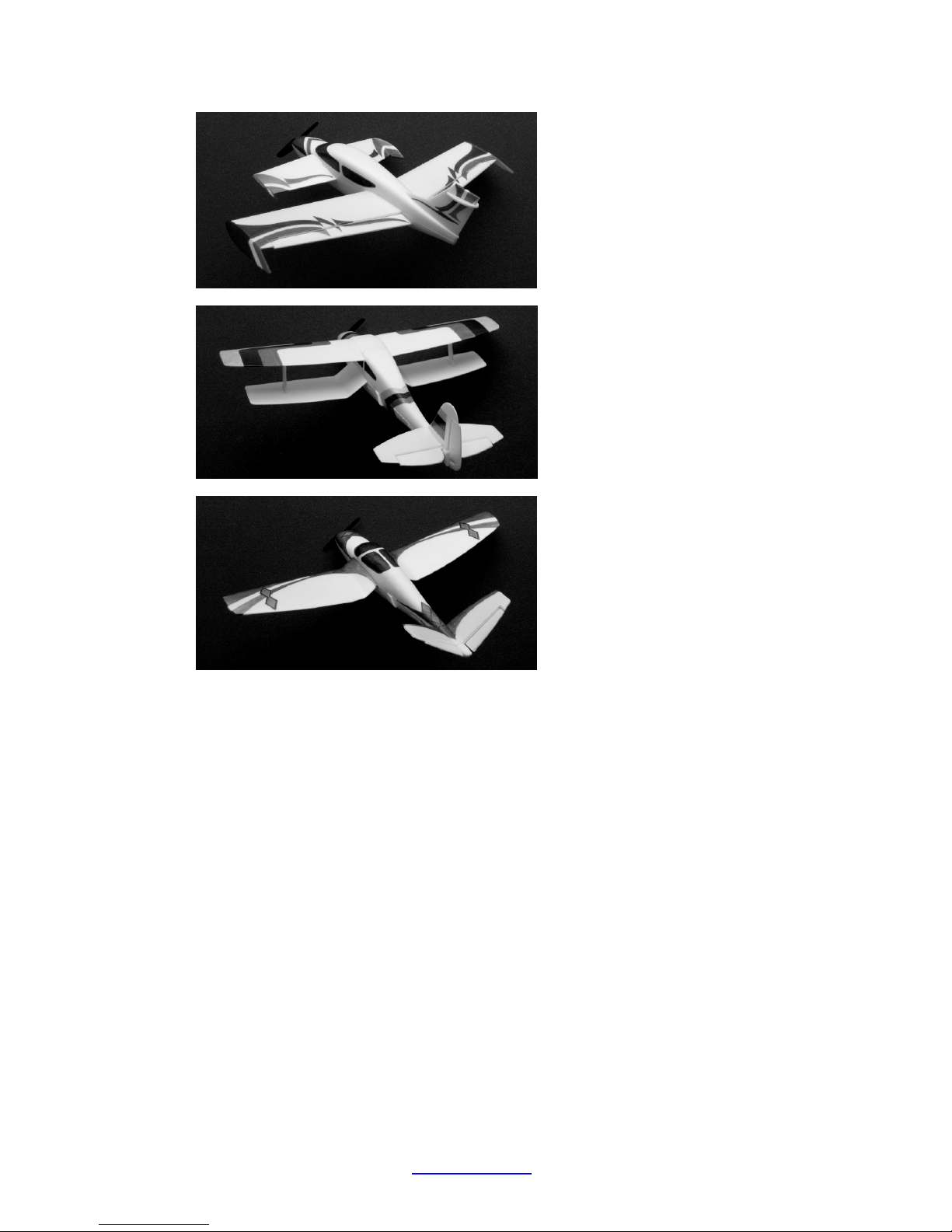
SNAP&FLY -- Modularized RC Airplanes
www.itcanfly.com 1
SNAP&FLY Quick Start
Rotating propellers and moving airplanes can cause bodily injury or property damage. Do not
operate this product in places where injury to people or damage to property might occur. For safe
usage of LiPo batteries it is essential to follow the proper guidelines to handle them. Users are
strongly recommended to read and understand the entire content of the “Owner’s Manual”.
A. Pre-flight
1. Insert 4 1.5 volts AA sized batteries into the transmitter battery compartment;
2. Charge the supplied LiPo batteries using the built-in LiPo battery charger in the
transmitter;
3. Chose an airplane module;
4. Select control mixing type at the transmitter according to airplane selected;
5. Make the control frequency selection at the transmitter;
6. Connect a fully charged LiPo battery to the receiver to power it up;
7. Turn on the transmitter and establish frequency-lock with the receiver;
8. Connect the base module to the plane module;
9. Check control surface responses to confirm the proper mix selection and control linkage
connections;
10. Check control surface neutral positions and travel ranges, apply necessary trim if
needed;
11. Check throttle control response;
B. Switch the Plane Module
1. Disconnect the base module from the airplane module to be replaced;
2. Chose a desired airplane module;
3. Select control mixing type at the transmitter according to airplane selected;
4. Replace or reconnect the LiPo battery if needed. If so, or if the receiver LED is flashing
turn the transmitter off then on again to establish frequency lock with the receiver.
5. Proceed from step 8 in section A with the desired airplane module.
C. Resume flight from crash
1. Check for damage in the base module and the plane module. Repair or replace parts if
necessary.
2. Proceed from step 4 in section B.
D. After flight
1. Disconnect the base module from the plane module;
2. Disconnect the LiPo battery from the receiver;
3. Turn off the transmitter;
4. Charge the LiPo battery if needed, and store the LiPo batteries properly;
E . Users' Warning Statement
Changes or modification not expressly approved by the responislbe party could void the user's
authority to use the equipment