CompAir L07RS Service manual

Original Operating and Service Manual
Screw Air Compressor
L07 - L11, L07RS - L11RS
L07FS - L11FS, L07RS FS - L11RS FS
V2
●
GB
●
CDN
●
USA
Id. no. ZS1066273 / 03 - December 2011


Deutsche Basis-BA: ZS1066271 / 03 1
General Information
These compressors are for compressing atmospheric air and are not suitable for compressing any other gas. They are
designed and manufactured to give optimum performance with long life and reliability.
This manual gives the user all the information required to install and operate the compressors and carry out the regular
schedules for servicing and maintenance, which will ensure the maximum satisfactory service life.
Servicing facilities and the supply of genuine replacement parts are provided through a worldwide network of Gardner
Denver Companies and Distributors. If replacement parts are needed, the user should, in the first instance, contact the
local Gardner Denver Company or Distributor.
The information given in this manual was correct at the time of printing, however, as part of continuous development,
modifications to parts and procedures may be made without notice which could affect the servicing requirements of the
compressors. Before any servicing or maintenance work is undertaken the user is advised to contact the local Gardner
Denver Company or Distributor who is supplied with revised and up-dated information.
In any communication concerning the compressor it is essential to quote the MODEL, SERIAL NUMBER and where
possible the YEAR of MANUFACTURE.
All pressure data given in this manual refer to overpressures (pressure gauge pressures) unless specified otherwise.
Maintenance
To ensure the continued trouble-free operation of the compressor unit it is important that periodic maintenance and
servicing is carried out in accordance with the information given in the ‘Maintenance’ section of this manual. To assist in
this matter your local Gardner Denver Company or Distributor can provide a number of optional maintenance agreements
to suit your requirements. These agreements provide the user with the expertise of our factory trained technicians and
the guarantee that only Genuine CompAir parts will be used.
Warranty
The conditions of the Gardner Denver Warranty are set out in the Company’s standard Conditions of Sale available from
the Gardner Denver Company or Distributor supplying the machine.
USE ONLY COMPAIR GENUINE PARTS. YOUR WARRANTY COULD BE
AFFECTED IF A SERVICE OR REPAIR IS CARRIED OUT USING
NON-GENUINE PARTS.

Data sheet for users
2
*)
*)
*)
Fig. 1
*) The values on the type plate are maximum values.
Your CompAir distributor
Name:
Address: ______________________________________________________________________________________
______________________________________________________________________________________
______________________________________________________________________________________
Telephone: Fax:
Contact: Spare Parts:
Service:

1. Foreword
3
1Foreword
1.1 Notes on the compressor
CompAir screw compressors are the result of many
years of research and development. These
prerequisites combined with high quality standards
guarantee the manufacture of screw compressors
providing a long service life, high reliability and cost-
effective operation. It stands to reason that all
requirements concerning environmental protection are
met.
1.2 Intended use
The machine/unit has been constructed in accordance
with state-of-the-art technology and the recognized
safety regulations. Nevertheless, its use may constitute
a risk to life and limb of the user or third persons or
cause damage to the machine or to other material
property, if
•it is not used as intended,
•it is operated by unqualified personnel,
•it is improperly modified or changed,
•the safety regulations are not observed.
Therefore, any person entrusted with the operation,
maintenance or repair of the machine must read and
follow the safety regulations. If required, this has to be
acknowledged by signature.
In addition,
•relevant accident prevention regulations,
•generally recognized safety regulations and
•national regulations
have to be observed.
The machine/unit must only be used in technically
perfect condition and in accordance with its intended
use and the instructions set out in the operating
manual, and only by safety-conscious persons who are
fully aware of the risks involved in operating the
machine/unit! Any functional defects, especially those
affecting safety, have to be rectified immediately (or
rectified by others)!
The machine/unit is designed exclusively for the
generation of compressed air to power air-driven
devices. Using the machine/unit for purposes other than
those mentioned above is considered contrary to its
intended use. The manufacturer/supplier cannot be held
responsible for damage resulting from such use. The
risk of such misuse lies solely with the user.
Operating the machine within the limits of its intended
use also involves observing the instructions set out in
the operating manual and complying with the inspection
and maintenance directives.
1.3 Maintenance
Carefully performed maintenance is imperative, this
ensures that your screw compressor can meet all the
requirements placed upon it. It is therefore imperative to
adhere to the specified maintenance intervals and to
carry out the maintenance work with particular care,
especially when the unit is utilized under harsh
operating conditions.
Servicing
Please contact your authorized CompAir dealer in the
case of malfunctions or when spare parts are required.
In the case of damage, our fully trained personnel will
ensure that a quick and proper repair is carried out
using genuine CompAir spare parts. Genuine CompAir
spare parts are manufactured utilizing state-of-the-art
technology, thus guaranteeing the further reliable
operation of the unit.
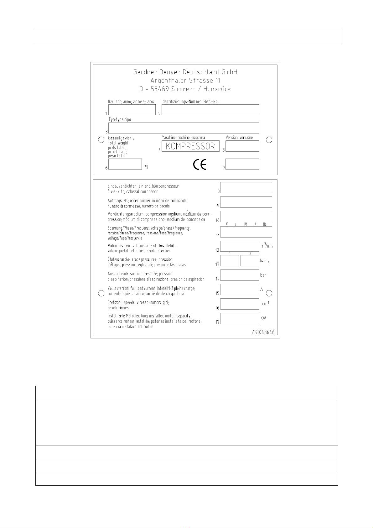
In case of queries
Please enter the data on the nameplate of your
compressor into the nameplate shown in (Fig. 1 on
page 2). In the case of queries or spare parts orders,
please refer to the compressor type indicated on the
nameplate, the identification no. and the year of
construction. With this information at hand it can be
guaranteed that you will receive the right information or
required spare parts.
1.4 Notes
General
These operating instructions are intended to familiarize
the user with the machine/unit and its intended use. The
instructions contain important notes on how to operate
the compressor safely, properly and cost-effectively.
Observing these instructions helps to avoid risks, to
reduce repair costs and downtimes and to increase the
reliability and service life of the machine/unit.
The operating instructions have to be supplemented by
the respective national rules and regulations regarding
the prevention of accidents and environmental
protection. They must always be available at the
location of the machine/unit. The operating instructions
must be read and followed by any person carrying out
work in connection with the machine/unit, e.g.
operation, including setting up, trouble-shooting in the
operation cycles, disposal of production waste, care,
service, and disposal of waste fuels and consumables,
upkeep (maintenance, inspection, repair), transport.

1. Foreword
4
Besides the operating instructions and the binding
regulations for the prevention of accidents, which are
valid in the country and place of operation of the
machine/unit, the generally recognized technical
regulations for safe and proper working have also to be
observed.
Guarantee
Operate this compressor only if you have an exact
knowledge of the machine taking into respect these
instructions.
Gardner Denver cannot be held responsible for the safe
operation of the machine/unit if it is used in a manner
which does not correspond to the intended use, or for
other applications which are not mentioned in these
instructions.
Warranty claims will not be accepted in the case of
•Operating errors
•Incorrect maintenance
•Wrong auxiliary materials
•Use of spare parts other than CompAir genuine
spare parts
•Modifications and changes to the installation
The warranty and liability conditions of the general
terms and conditions of Gardner Denver will not be
extended by the notes above.
Any unauthorized change to the compressor unit/
station, or the installation of components not accepted
by the manufacturer (e.g. fine separator) will result in
the withdrawal of the CE mark. As a consequence, any
liability and warranty claims will not be accepted by the
manufacturer.
Safety regulations
Danger
The safety regulations in chapter 3 of the operating
instructions have to be strictly observed.
Technical changes
In the course of technical development we reserve the
right to modify the units without further notice.

2. Table of contents
5
2Table of contents
1Foreword...............................................................................................................................................................................3
1.1 Notes on the compressor .............................................................................................................................................3
1.2 Intended use..................................................................................................................................................................3
1.3 Maintenance..................................................................................................................................................................3
1.4 Notes .............................................................................................................................................................................3
2Table of contents .................................................................................................................................................................5
3Safety regulations ...............................................................................................................................................................7
3.1 Identification of safety guidelines .................................................................................................................................7
3.2 General safety instructions...........................................................................................................................................7
3.3 Changes and modifications to the machine ................................................................................................................8
3.4 Installation and normal operation.................................................................................................................................8
3.5 Special work/maintenance .........................................................................................................................................10
3.6 Warning of special dangers........................................................................................................................................12
3.7 Storage of compressors .............................................................................................................................................13
3.8 Symbols and explanations .........................................................................................................................................14
4Design and functioning ....................................................................................................................................................18
4.1 Design of the unit ........................................................................................................................................................18
4.1.1 Design of the unit - L07-L11 (RS)...................................................................................................................18
4.1.2 Design of the unit - AirStation L07FS-L11FS (RS)........................................................................................19
4.2 Schematic diagram .....................................................................................................................................................20
4.3 Oil circuit......................................................................................................................................................................21
4.4 Air circuit......................................................................................................................................................................21
4.5 System control ............................................................................................................................................................21
4.5.1 System control L07-L11 / L07FS-L11FS........................................................................................................21
4.5.2 System control L07RS-L11RS and AirStation L07RS FS-L11RS FS...........................................................22
4.6 Hood (opening/closing)...............................................................................................................................................23
5Transport and installation ................................................................................................................................................24
5.1 Transport .....................................................................................................................................................................24
5.2 Installation ...................................................................................................................................................................25
6Preparations for commissioning ....................................................................................................................................26
6.1 Cooling air volume/minimum cross ............................................................................................................................26
6.2 Compressed air connection........................................................................................................................................27
6.3 Electrical connection...................................................................................................................................................28
6.3.1 Electrical connection (EUROPE-Version only)..............................................................................................28
6.3.2 Electrical connection (USA/CANADA-Version only) .....................................................................................30
6.4 Electric motor fasteners for secure transportation ....................................................................................................31
6.5 Oil level check .............................................................................................................................................................32
6.6 Sound pressure level ..................................................................................................................................................32
7Commissioning ..................................................................................................................................................................33
7.1 First commissioning ....................................................................................................................................................33
7.2 Routine commissioning ..............................................................................................................................................34
7.3 Commissioning after malfunction...............................................................................................................................34

2. Table of contents
6
8Control system...................................................................................................................................................................35
8.1 General........................................................................................................................................................................35
8.2 Keys.............................................................................................................................................................................35
8.3 Status indicator (display / light signals) .....................................................................................................................35
8.4 Displaying / changing values......................................................................................................................................36
8.4.1 Selecting values ..............................................................................................................................................36
8.4.2 Changing values .............................................................................................................................................36
8.5 Default settings ...........................................................................................................................................................36
8.5.1 Selecting language..........................................................................................................................................36
8.5.2 Setting network pressure (apart from L07RS-L11RS) ..................................................................................36
8.5.3 Setting line pressure (only L07RS-L11RS)....................................................................................................37
8.5.4 Setting time/date (timer) .................................................................................................................................37
8.6 Starting the unit ...........................................................................................................................................................37
8.7 Switching off the unit...................................................................................................................................................37
8.8 Emergency off button..................................................................................................................................................37
8.9 Acknowledging warning / fault messages .................................................................................................................38
8.9.1 Warning messages .........................................................................................................................................38
8.9.2 Fault messages...............................................................................................................................................38
8.10 Menu structure (apart from L07RS-L11RS) (values are examples).........................................................................39
8.11 Menu structure (only L07RS-L11RS) (values are examples) ...................................................................................40
9Service and maintenance.................................................................................................................................................41
9.1 Maintenance recommendations.................................................................................................................................41
9.2 Maintenance electric motor ........................................................................................................................................41
9.3 Maintenance and inspection schedule ......................................................................................................................41
9.4 Oil change ...................................................................................................................................................................44
9.5 Change of oil filter cartridge .......................................................................................................................................45
9.6 Change of the fine separator cartridge ......................................................................................................................46
9.7 Change of air intake filter............................................................................................................................................46
9.8 Safety valve.................................................................................................................................................................47
9.9 Changing V-belts/automatic tensioning system ........................................................................................................48
9.10 Connecting terminals in the switch cabinet/control transformer setting...................................................................48
9.11 Fittings .........................................................................................................................................................................48
9.12 General maintenance and cleaning ...........................................................................................................................49
9.13 Clean / change cooling air filter mat ..........................................................................................................................49
9.14 Inspection intervals for pressure vessels and electrical installations.......................................................................50
9.15 Maintenance information and lubricant recommendations for stationary compressors..........................................50
10 Trouble-shooting ...............................................................................................................................................................51
11 Annex...................................................................................................................................................................................53
11.1 Technical data EUROPE version L07-L11 50 Hz .....................................................................................................53
11.2 Technical data EUROPE version L07-L11 60 Hz .....................................................................................................54
11.3 Technical data EUROPE version L07RS ..................................................................................................................55
11.4 Technical data EUROPE version L11RS ..................................................................................................................56
11.5 Technical data USA/Canada version L07-L11 60 Hz ...............................................................................................57
11.6 Technical data USA/Canada version L07RS ............................................................................................................58
11.7 Technical data USA/Canada version L11RS ............................................................................................................59
11.8 Layout plan L07-L11 and L07RS-L11RS...................................................................................................................60
11.9 Layout plan AirStation L07FS-L11FS and L07RS FS-L11RS FS.............................................................................61
11.10 Declaration of conformity .........................................................................................................................................62

3. Safety regulations
7
3Safetyr eg ulations
3.1 Identification of safety guidelines
Gardner Denver is not liable for any damage or injury
resulting from the non-observance of these safety
instructions or negligence of the usual care and
attention required during handling, operation,
maintenance or repair, even if this is not explicitly
mentioned in these operating instructions.
If any of the regulations contained in these instructions
- especially with regard to safety - does not correspond
to the local legal provisions, the stricter of both shall
prevail.
These safety regulations are general and valid for
various types of machines and equipment. It is
therefore possible that some references do not apply to
the unit(s) described in these instructions.
Danger
Passages marked with this sign indicate a possible
danger to persons.
Important
Passages marked with this sign indicate a possible
danger to machines or part of machines.
Note
Passages marked w
i
th this sign provide technical
information on an optimal cost-effective use of the
machine.
3.2 General safety instructions
Organizational measures
The operating instructions must always be at hand at
the place of operation of the machine/unit!
In addition to the operating instructions, all other
generally applicable legal and other mandatory
regulations relevant to accident prevention and
environmental protection must be adhered to and
passed on to others! These compulsory regulations
may also deal with the handling of hazardous materials
or the issuing/wearing of personal protective equipment,
or traffic regulations.
Instructions, including supervisory responsibility and
duty of notification for taking into account in-plant
factors, for example regarding work organization,
sequences of operations, personnel assigned to certain
tasks, are to be added to the operating manual.
The personnel entrusted with working on the machine
must have read the operating instructions and in
particular the chapter on safety regulations before
starting work. Reading the instructions after work has
begun is too late. This applies especially to persons
working only occasionally on the machine, e.g. for
setting up or maintenance.
Check on a regular basis that the personnel are
carrying out the work in compliance with the operating
instructions and that they are paying attention to the
safety requirements!
For safety reasons, long hair must be tied back or
otherwise secured, garments must be close-fitting and
no jewellery - such as rings - may be worn. Injury may
result from being caught up in the machinery or from
rings catching on moving parts! As necessary or as
required by regulations, personal protective equipment
should be used.
Observe all safety and warning notices attached to the
machine/unit!
See to it that safety instructions and warnings attached
to the machine are always complete and perfectly
legible.
In the case of safety-relevant changes to the machine/
unit or its operating behaviour, stop the machine/unit
immediately and report the fault to the responsible
department/person!
Spare parts have to comply with the technical
requirements specified by the manufacturer. This can
always be ensured by using original spare parts.
Hydraulic hoses have to be changed within stipulated
and periodic intervals, even if no safety-relevant faults
have been detected!
Adhere to prescribed intervals or those specified in the
operating instructions for routine checks and
inspections!

3. Safety regulations
8
For the execution of maintenance work, tools and
workshop equipment adapted to the task on hand are
absolutely indispensable.
The personnel must be made familiar with the location
and operation instructions of fire extinguishers !
Observe all fire-warning and fire-fighting procedures!
Limit values (pressures, time settings, etc.) have to be
permanently identified!
Selection and qualification of personnel;
basic responsibilities
Work on/with the machine/unit must be carried out by
reliable personnel only. Statutory minimum age limits
must be observed!
Employ only trained or instructed personnel and clearly
set out the individual responsibilities of the personnel
for operation, set-up, maintenance and repair!
Ensure that only authorized personnel work on or with
the machine!
Define the machine operator's responsibilities giving the
operator the authority to refuse instructions by third
persons that are contrary to safety regulations.
Do not allow persons to be trained or instructed or
persons taking part in a general training course to work
on or with the machine/unit without being permanently
supervised by an experienced person!
Work on the electrical equipment of the machine/unit
must be carried out only by a skilled electrician in
accordance with electrical engineering rules and
regulations.
Work on system elements such as hoses may only be
carried out by personnel with special knowledge and
experience of hydraulics!
3.3 Changes and modifications to the
machine
Do not make any changes, modifications or
attachments to the machine/unit, which could affect
safety, without the supplier's prior permission!
Unauthorized changes to the machine are not permitted
for safety reasons.
Original parts were especially designed for this
machine. We would like to point out that we have not
released and will not release parts and special
accessories which have not been supplied by us. The
installation and/or use of such products can therefore
affect the active and/or passive safety.
The manufacturer is not liable for damage resulting
from the use of non-original parts or special
accessories. This applies also to the installation and
setting of safety equipment and valves as well as to
welding on structural or pressurized parts.
3.4 Installation and normal operation
Installation
In addition to the general technical operation in
accordance with the stipulations of the local authorities,
we would like to refer in particular to the following
regulations.
For the lifting of a compressor, a suitable lifting
mechanism is to be used, which meets the local safety
regulations. All loose or slew able parts must be safely
fixed before the machine can be lifted. It is strictly
prohibited to stay in the danger zone of a lifted load.
The correct method of lifting (according to the operating
instructions of the load suspension device) has to be
ensured.
All blind flanges, plugs, caps and bags with drying
agent have to be removed prior to the installation of the
pipes. Distributing pipes and pipe connections have to
be of the proper size and suitable for the relevant
operating pressure.
The system must be set up on a level surface with full
contact between its base frame and the supporting
surface.
The system has to be installed in such a way that it is
adequately accessible and the required cooling is
guaranteed. Never block the air intake. Make sure that
the ingress of humidity via the intake air is kept to a
minimum.
The air intake is to be located so that no hazardous
constituent (solvent vapour, etc., but also dusts and
other hazardous material) can be sucked in. This
applies also to flying sparks.
The air intake is to be positioned so that no loose
clothing of persons can be sucked in. Make sure that
the pressure line from the compressor to the after
cooler or the air circuit can expand under heat and does
not come into contact with inflammable material.
The pressure line connected to the air outlet of the
system must be fitted stress-free. When connecting the
compressor on the mains side to the compressed air
system available at the customer‘s end, check the
operating temperatures and operating pressures
required and examine the required connecting flange or
the connection thread for proper functioning.
In the case of connections by means of connecting
hoses, take appropriate measures to prevent whipping
of the loose end in the event that the hose connection
tears off.

3. Safety regulations
9
If a remote control is used, the system must carry a
clearly visible sign with the following note: Attention!
This installation is operated by remote control and can
start up without prior warning!
As an additional safety measure, persons, who start
remotely controlled systems, have to take sufficient
safety precautions in order to ensure that nobody is
checking the system or working on it. For this, a label
with a corresponding warning notice has to be attached
to the remote control equipment.
Compressed air and cooling water lines have to be
clearly marked in line with the local regulations.
If a system comprises several compressors, hand
operated isolator valves have to be installed in order to
be able to shut off each machine individually. When
operating pressure systems, do not rely on the
effectiveness of start valves alone to isolate these
systems.
Safety equipment, protective covers or insulation must
not be removed or modified. Any pressure reservoir,
which is located outside the system, the permissible
operating pressure of which is higher than the
atmospheric pressure and which is fitted with two or
more pressure supply lines, has to be equipped with
additional safety equipment, which will automatically
prevent the admissible operating pressure from rising
by more than 10%.
The installed unit-specific safety valves only assume
the pressure safeguarding function of the compressor
unit provided in currently valid standards and
regulations.
For pressure components/systems mounted to the
connecting flange on the pressure side, a pressure
safety device (safety valve or similar) has to be installed
taking into account the weakest pressurized
component.
The min. and max. temperatures of +1 °C/33.8 °F and
+45 °C/113°F are also valid for the intake air. Pipes
and/or other parts with a surface temperature higher
than 70 °C/158 °F have to be suitably identified and
shielded against touching.
Electrical connections must meet the local regulations.
Power units must be connected to earth and protected
from short-circuits by means of fuses.
Cold dryer
Wherever possible, the cold dryer should be installed in
a place where the ambient air is as clean as possible
and where the temperatures never rise above or fall
below the respective limit values as indicated in the
operating instructions. If required, the cooling air is to
be taken from a cleaner, cooler or warmer area via an
intake channel; depending on the size of the machine,
an additional fan could turn out to be necessary.
If the room temperature can fall below zero, the
condensation drain system must be protected from
freezing, e.g. by means of a steam heater.
If it is possible that the intake temperature of the air will
exceed, from time to time, the admissible maximum
specified in the operating instructions, a precooler with
condensate drain is to be installed before the dryer.
Tests or repair work on the coolant circuit may only be
carried out in a well vented room. Never breath in
coolant vapour; if necessary, wear a breathing mask.
Always wear protective goggles and gloves. If skin
comes into contact with coolants, rinse well with water.
Never take off or tear up clothes but rinse them well
with water until the coolant is washed off; then see a
doctor.
Condensate drain
The drain hose for condensate discharge is to be
connected to the drains or to a collecting reservoir, if
local regulations prohibit direct discharge to the drains.
In connection with this, it must be taken into account
that the condensate from compressors with oil-
lubricated pressure chambers can contain oil.
Normal operation
Take the necessary precautions to ensure that the
machine is used only when in a safe and reliable state!
Operate the machine only when all protective
equipment, emergency shut-off equipment, sound-
proofing elements and extraction devices are in place
and fully functional!
Check regularly that
•all means of protection are correctly fitted and fixed,
•all hoses and/or pipes within the system are in good
condition, firmly fixed and do not chafe,
•there are no leakages (fuel, oil or coolant),
•all fittings are firmly tightened,
•all wires are connected correctly and are in good
condition,
•all safety valves and other pressure relief
mechanisms are in good order and not blocked by
e.g. dirt or paint,
•the safety mechanisms are fully functional.
If compressed air hoses are used, they must be of the
proper size and suitable for the relevant operating
pressure. Do not use chafed, damaged or poor-quality
hoses.
Only use hose couplings and fittings of the right type
and the correct size.

3. Safety regulations
10
Before blowing through a hose or an air pipe ensure
that the open end is positively held. A free end whips
and can cause injuries.
Before decoupling a hose ensure that it is pressureless.
Refrain from any working method which is doubtful in
terms of safety.
Never play around with compressed air!
Never aim compressed air at your skin or at other
persons!
Never use compressed air to clean your clothing.
When using compressed air to clean equipment take
the utmost care and always wear protective goggles.
The compressed air generated by these compressors
must never be used for breathing unless it has been
conditioned for those applications in line with the “safety
requirements for respiratory air”.
Never use the machine in an environment where
inflammable or poisonous vapour can be sucked in.
Never operate the system at pressures and
temperatures below or above the values indicated in the
technical data sheet.
The access panels, etc. have to be closed during
operation.
Check the machine/unit at least once per shift for visible
damage and faults! Report any changes (including
changes in the machine’s operating behaviour) to the
responsible department/person immediately. If
necessary, stop and lock the machine immediately!
In the case of malfunction, stop the machine/unit
immediately and lock it! Have any defects rectified
immediately!
Observe the start-up and stopping procedures and the
control displays according to the operating instructions.
Before starting up or setting the machine in motion,
ensure that nobody is at risk.
Do not cut off or remove extraction or venting facilities
while the machine is running.
3.5 Special work/maintenance
Carefulness
Observe the adjusting, maintenance and inspection
activities and intervals set out in the operating
instructions, including information on the replacement of
parts and equipment. These activities may be carried
out by skilled personnel only.
Brief the operating personnel prior to starting special
operations or maintenance work! Appoint a person to
supervise the activities!
Maintenance and repair work may only be carried out
under the supervision of a person who is qualified for
this work.
Oil losses result in a slippery floor. Therefore, always
clean the floor and the outside of the machine prior to
starting the maintenance work.
Checks, maintenance and repair work may only be
carried out with the screw compressor being at rest and
depressurized. Protective equipment to be removed for
this work, has to be refitted after completion of these
activities. Operation of the machine without protective
equipment is not permitted. When working on a running
screw compressor system, working clothes have to be
close-fitting.
If the machine/unit is completely shut down for
maintenance and repair work, it must be secured
against inadvertent restarting:
•Lock the main command elements and remove the
key and/or
•attach a warning sign to the main switch.
Always use the correct tools for maintenance and repair
work.
Never use inflammable solvents or carbon tetrachloride
to clean parts. Take precautions against poisonous
vapours from cleaning agents.
In any work concerning the operation, conversion or
adjustment of the machine and its safety-oriented
devices or any work related to maintenance, inspection
and repair, always observe the start-up and shutdown
procedures set out in the operating instructions and the
information on maintenance work.
Ensure that the maintenance area is adequately
secured.
To lower the risk of accidents, individual parts and large
assemblies being moved for replacement purposes
should be carefully attached to lifting tackle and secured.
Use only suitable and technically correct lifting gear and
only utilize suspension systems with adequate lifting
capacity. Never work or stand under suspended loads!
During maintenance and when carrying out repair work,
cleanliness is very important. Avoid the ingress of dirt
by covering parts and free openings with a clean cloth,
paper or adhesive tape.
After the completion of each repair, check that tooling or
loose parts have not been left in the or on top of the
machine, drive motor or drive equipment and ensure
that no cloth has been left inside these units.
Be careful when the screw compressor system is in
operation.

3. Safety regulations
11
Maintenance/rectification of faults
The employer has to inform the employee of the
dangers possibly arising during the repair and
maintenance of the machine/unit as well as on how to
avoid them; the employee has to observe all measures
for safety at work. Safety equipment for the prevention
or elimination of danger has to be maintained regularly
and functionally checked at least once a year. Faults
observed have to be immediately rectified and/or
reported to the responsible person.
Use only original spare parts.
Only carry out maintenance and repair work when the
system is not in operation and the power supply
disconnected. Ensure that the power unit cannot be
switched on inadvertently.
Before removing or opening pressurized components,
positively isolate any source of pressure and
depressurize the entire system.
Never weld near oil systems or carry out any other work
requiring heat. Pressure reservoirs or components and
pipes containing oil have to be drained completely and
cleaned, for example by means of a steam jet, before
beginning such work.
Never weld any pressure reservoir or change it in any
way.
If work which produces heat, flames or sparks has to be
carried out on a machine, the adjacent components
have to be protected by means of non inflammable
material.
Before releasing the power unit for operation after
maintenance or overhaul, check that the operating
pressures, temperatures and time settings are correct
and that the regulating and shut-down equipment
function properly.
Every six months, check the pressure pipe and
pressure vibration damper for carbon deposits. If
excessive deposits are found, they should be removed.
Motor, air filter, electrical components and regulating
equipment have to protected from the ingress of
humidity, e.g. when cleaning the system by means of a
steam jet.
Under no circumstance must the sound-proofing
material be removed or modified.
Never use etching solvents which could attack the
materials used.
If indicated or if there is any suspicion that an internal
part of the machine has run hot, the machine has to be
shut down.
In order to avoid an increase in the operating
temperature, check and clean the heat transfer surfaces
(cooling fins, intermediate cooler, water cooling jackets,
etc.) at regular intervals. Prepare a plan of the most
favourable cleaning intervals for each machine.
Avoid damage to the safety valves and other pressure
reducing components. Check in particular for clogging
caused by paint, oil carbon or the accumulation of dust,
which could deteriorate the effectiveness of these
components.
Insulation or protective shielding, the temperature of
which may exceed 70 °C/158 °F and which could be
erroneously touched by the personnel, must not be
removed before these parts have cooled down to room
temperature.
Check the accuracy of pressure and temperature
indicators at regular intervals. If the admissible
tolerance limits have been exceeded, these devices
have to be replaced.
Before removing or overhauling a compressor, a motor
or another machine, ensure that all moveable parts of a
mass of more than 15 kg cannot move or roll away.
After completion of repair work, always verify that no
tools, loose parts or cloths have been left in or on the
machine, drive motor or drive equipment. Machines
performing a back and forward main movement have to
be cycled at least once, rotating machines have to be
cycled several times in order to ensure that there are no
mechanical faults in the machine or the drive member.
Check the direction of rotation of the electric motors
during first commissioning and after each modification
of the electrical connections in order to prevent the
compressor from being damaged.
The fastening of loads and the instructing of crane
operators should be entrusted to experienced persons
only. The person giving the instructions must be within
sight or voice contact with the operator.
For carrying out overhead assembly work always use
specially designed or otherwise safety-orientated
ladders and working platforms. Never use machine
parts as a climbing aid. Wear a safety harness when
carrying out maintenance work at greater heights.
Keep all steps, handles, handrails, platforms, landings
and ladders free from dirt, snow and ice! Clean the
machine, especially connections and threaded unions,
of any traces of oil, fuel or preservatives before carrying
out maintenance or repair work! Never use aggressive
detergents! Use lint-free cleaning rags!
Before cleaning the machine with water or steam jet
(high pressure cleaner) or other cleaning agents,
cover/mask all openings which have to be protected
from the ingress of water, steam or detergents for
safety and/or functional reasons, in particular electric
motors and switch cabinets.
After cleaning, remove the covers/masking completely !
Check all hydraulic oil lines for leakage, loose fittings,
abrasion and damage after cleaning. Any defect must
be rectified immediately!
Always re-tighten screwed connections which have
been loosened for maintenance and repair work.

3. Safety regulations
12
If the set-up, maintenance or repair require the
demounting of safety equipment, this equipment has to
be remounted and checked immediately after these
activities.
Ensure that consumables and replacement parts are
disposed of in a safe and environmentally friendly
manner.
3.6 Warning of special dangers
Electric energy
Use only original fuses with the specified current rating.
Switch off the machine/unit immediately if trouble
occurs in the electric system.
Work on the electrical system or equipment may only
be carried out by a skilled electrician or by specially
instructed personnel under the control and supervision
of such an electrician and in line with the relevant
electrical engineering rules.
If regulations require, the power supply to parts of
machines and plants on which inspection, maintenance
and repair work is to be carried out must be cut off.
Before starting any work, check the deenergized parts
for the presence of power and ground or short-circuit
them in addition to insulating adjacent live parts and
elements.
The electrical equipment of the machines/units is to be
inspected and checked at regular intervals. Defects
such as loose connections or scorched cables must be
rectified immediately.
Necessary work on live parts and elements must be
carried out in the presence of a second person who can
cut off the power supply in case of danger by operating
the emergency shutdown or main power switch. Secure
the working area with a red-and-white safety chain and
a warning sign. Use insulated tools only.
Before starting work on high-voltage assemblies and
after having cut out the power supply, the feeder cable
must be grounded, and components, such as
capacitors, short-circuited with a grounding rod.
Always check a correct power supply to the compressor
before commissioning. The voltage supply has to fulfill
the requirements of EN60204-1/IEC60204-1 for such
kind of industrial equipment. Insufficient power quality
could have a strong effect on health & safety and may
constitute a risk to life and limb of the user or third
persons or cause damage to the machine or also the
environment around.
Gas, dust, steam and smoke
Carry out welding, flame-cutting and grinding work on
the machine/unit only if this has been expressly
authorized, as there may be a risk of explosion and fire.
Before carrying out welding, flame-cutting and grinding
operations, clean the machine/unit and its surroundings
from dust and other inflammable substances and make
sure that the premises are adequately ventilated (risk of
explosion)!
Adhere to the regulations valid for the place of operation!
Observe any existing national regulations if work is to
be carried out in small rooms.
Hydraulics, pneumatics
Work on hydraulic equipment may only be carried out
by persons with special knowledge and experience of
hydraulics.
Check all lines, hoses and screwed connections
regularly for leaks and obvious damage. Repair
damage immediately. High pressure jets of oil may
cause injury and fire.
Depressurize all system sections and pressure pipes
(hydraulic system, compressed-air system) which are to
be removed in accordance with the specific instructions
for the assemblies concerned before carrying out any
repair work.
Hydraulic and compressed-air lines must be laid and
fitted properly. Ensure that no connections are
exchanged. The fittings, lengths and quality of the
hoses must comply with the technical requirements.
Noise
Sound-proofing elements on the machine/unit have to
be active during operation (i.e. sound-proofing panels
closed, etc.).
Where necessary, wear the personal hearing protection
prescribed.
Noise, even at a low level, can cause nervousness and
annoyance; over a longer period of time, our nervous
system can suffer serious damage. We therefore
recommend a separate machine room in order to keep
the noise of the machine away from the workshop.
•In order to consider all noise-relevant parameters
and to adequately protect the health of the operator,
the European Regulation 2003/10/EC must be
satisfied completely by the user.
•In states outside the European Community, the
respective noise protection directives must be taken
into consideration.
Take care that the noise transmission through walls and
frames does not result in too high a noise level in the
surrounding areas.

3. Safety regulations
13
Oils, greases and other chemical substances
When handling oils, greases and other chemical
substances, observe the safety regulations for this
product! Be careful when handling hot fuels and
consumables (danger of burning or scalding)!
Rooms subject to explosion hazards
Danger
Compressor units must never be operated in areas
subject to explosion hazards!
(Exception: Special units with the corresponding
technical modifications)
3.7 Storage of compressors
All compressors are protected against corrosion at the
factory for transport and for brief storage before
commissioning.
If the compressors are to be stored for period
exceeding six months, additional precautions must be
taken.
Compressors which are to be shut down for a lengthy
period must also be protected from corrosion.
Since corrosion occurs more quickly in damp
atmospheres than in dry conditions, it is not possible to
specify a maximum permissible standstill time which will
apply in all cases.
Note
The following aspects must be taken into account for
storage of storing compressors.
The compressor should be stored in a dry building
which should be heated if possible.
This is particularly true during the months of winter.
If there is a risk that the temperature will fall or rise
above the limits of -10 °C/14 °F to +65 °C/149 °F , the
electrical controller must be removed and stored in
ambient temperatures of +5 °C/41 °F to +30 °C/86 °F.
Before commissioning the compressor all the electrical
and electronic components and units should be
checked for the ingress of water or condensation.

3. Safety regulations
14
3.8 Symbols and explanations
Carefully read the operating manual before
commissioning or servicing this compressor.
Never breathe in compressed air from this system.
Never operate the unit with open doors or loose access
panels.

3. Safety regulations
15
Warning: Hot surface
Warning: Pressurized part or system
Warning: This system can start up by means of a
remote control or automatically after a power
failure.

3. Safety regulations
16
Warning: The system continues to run for 30 seconds
after pressing the O-key
Warning: Danger of electric shock
Attention: Lifting point

3. Safety regulations
17
Attention: Check and, if required, re-tighten
connection terminals. For further details,
see the operating instructions.
Attention: Electric motor fasteners
Electric motor fasteners used for securing
the unit during transportation have to be
removed prior to commissioning (see also
chapter 6.4).
Attention: Danger of electric shock from loaded
condensers! Please always first disconnect
the system from the power supply and wait
another 10 minutes before touching the
electrical components. The power
condensers require this time in order to
discharge!

4. Design and functioning
18
4Designa n d f un ctioning
4.1 Design of the unit
4.1.1 Design of the unit - L07-L11 (RS)
Fig. 2a L07-L11
1
Intake filter
2
Intake regulator
3
Electric motor
4
Screw compressor
5
Belt drive
6
Pressure reservoir
7
Oil fine separator
8
Oil filling port
9
Oil drain
10
Oil level indicator
11
Oil filter
12
Oil cooler
13
Safety valve
14
Pressure holding and check valve
15
Air cooler
16
Oil fine separator extractor
17
Oil temperature regulator
18
Cooling air ventilator
19
Cooling air inlet filter mat
20
Compressed air outlet
21
Base frame
23
Control keypad
24
EMERGENCY OFF push-button
25
Control cabinet
26
Supply cable gland
27
Final compression temperature
sensor
28
Network pressure sensor
29
Final compression pressure
sensor
30
Opening for lifting gear
This manual suits for next models
7
Table of contents
Other CompAir Air Compressor manuals

CompAir
CompAir L07 User manual

CompAir
CompAir C30 User manual

CompAir
CompAir V-Compact Series User manual

CompAir
CompAir L37S-75 User manual

CompAir
CompAir 5280D.1.IAC Service manual

CompAir
CompAir H5211 User manual

CompAir
CompAir D50H RS Service manual

CompAir
CompAir L15 Service manual

CompAir
CompAir HV04 Troubleshooting guide

CompAir
CompAir CL15SS User manual