Composite-ARF Extra 300SX User manual

Composite-ARF Extra 300SX (2.6m span)
Instruction Manual
Composite-ARF Extra 300SX, 2.6 m
TAVS Technology version 1.01

Instructions for Extra 300SX IMAC-Airplane
Thank you very much for purchasing our Composite-ARF Extra 300SX all composite aircraft,
made with the revolutionary Total Area Vacuum Sandwich (TAVS) technology
It is based on our extremely successful Extra 330L (2.6m), which has been in production for 5
years, and assembly is almost identical. Therefore this Instruction Manual is actually an updat-
ed version of our 330L manual, and you will see some photos of the original 330L kit here, in dif-
ferent colour schemes - so please don’t get confused ! Of course, all the important areas that
have changed are shown, and the main changes between the 2 airframes are:
a) The 300SX has a Ø 40mm wing tube (instead of carbon blade spars)
b) The motor-dome is now molded as an integral part of the fuselage.
c) The Landing Gear mount is revised and reinforced, and LG leg cuffs are included.
d) A shorter clear canopy, & the canopy frame fixings are completed at the factory.
e) Elevator hinges now use the 4mm diameter tube system, instead of the 2mm Ø wires.
f) The Tank base and Rudder servo tray are modified to fit the wing tube structure.
*Instructions version 1.01 update includes note about wing tube length.
Before you get started building and setting-up your aircraft, please make sure you have read
this instruction manual several times, and understood it. If you have any questions, please
don’t hesitate to contact us. Below are the contact details:
Email: [email protected]
Telephone: Phone your C-ARF Rep!!! He will be there for you.
Website: http://www.composite-arf.com
Liability Exclusion and Damages
You have acquired a kit, which can be assembled into a fully working R/C model when fitted out
with suitable accessories, as described in the instruction manual with the kit.
However, as manufacturers, we at Composite-ARF are not in a position to influence the way you
build and operate your model, and we have no control over the methods you use to install,
operate and maintain the radio control system components. For this reason we are obliged to
deny all liability for loss, damage or costs which are incurred due to the incompetent or incorrect
application and operation of our products, or which are connected with such operation in any
way. Unless otherwise prescribed by binding law, the obligation of the Composite-ARF compa-
ny to pay compensation is excluded, regardless of the legal argument employed.
This applies to personal injury, death, damage to buildings, loss of turnover and business,
interruption of business or other direct and indirect consequent damages. In all circumstances
our total liability is limited to the amount which you actually paid for this model.
BY OPERATING THIS MODEL YOU ASSUME FULL RESPONSIBILITY FOR YOUR ACTIONS.
It is important to understand that Composite-ARF Co., Ltd, is unable to monitor whether you
follow the instructions contained in this instruction manual regarding the construction, operation
and maintenance of the aircraft, nor whether you install and use the radio control system
correctly. For this reason we at Composite-ARF are unable to guarantee or provide a
contractual agreement with any individual or company that the model you have made will
function correctly and safely. You, as operator of the model, must rely upon your own expertise
and judgement in acquiring and operating this model.
2

Supplementary Safety Notes
Pre-flight checking:
Before every session check that all the model’s working systems function correctly, and be sure
to carry out a range check.
The first time you fly any new model aircraft we strongly recommend that you enlist the help of
an experienced modeller to help you check the model and offer advice while you are flying. He
should be capable of detecting potential weak points and errors.
Be certain to keep to the recommended CG position and control surface travels. If adjustments
are required, carry them out before operating the model.
Be aware of any instructions and warnings of other manufacturers, whose product(s) you use to
fly this particular aircraft, especially engines and radio equipment.
Please don’t ignore our warnings, or those provided by other manufacturers. They refer to things
and processes which, if ignored, could result in permanent damage or fatal injury.
Attention !
This IMAC-Aircraft is a high-end product and can create an enormous risk for both pilot and
spectators, if not handled with care, and used according to the instructions. Make sure that you
operate your Extra according to the AMA rules, or those laws and regulations governing the
model flying in the country of use.
The engine, servos and control surfaces have to be attached properly. Please use only the
recommended engines, servos, propellers, and accessories supplied in the kit.
Make sure that the ‘Centre of Gravity’ is locat-
ed in the recommended place. Use the nose
heavy end of the CG range for your first flights,
before you start moving the CG back to a more
critical position for 3D-maneouvers. If you find
that you need to relocate your batteries or
even add weight in the aircraft to move the CG
to the recommended position, please do so
and don’t try to save weight or hassle. A tail
heavy plane, in a first flight, can be an enor-
mous danger for you and all spectators. Fix
any weights, and heavy items like batteries,
very securely to the plane.
Make sure that the plane is secured properly when you start the engine. Have at least 2 helpers
hold your plane from the tail end, or from behind the wing tips, before you start the engine. Make
sure that all spectators are behind, or far in front, of the aircraft when running up the engine.
Make sure that you range check your R/C system thoroughly before the first flight. It is absolute-
ly necessary to range check your complete R/C installation first WITHOUT the engine running.
Leave the transmitter antenna retracted, and check the distance you can walk before ‘fail-safe’
occurs. Then start up the engine, run it at about half throttle and repeat this range check with the
engine running. Make sure that there is no range reduction before ‘fail-safe’ occurs. Only then
3
NO !!!
Secure the plane
before starting the engine.
DANGER ZONES
NO NO

4
make the 1st flight. If you feel that the range with engine running is less then with the engine off,
please contact the radio supplier and the engine manufacturer and DON’T FLY at that time.
Check for vibrations through the whole throttle range. The engine should run smoothly with no
unusual vibration. If you think that there are any excessive vibrations at any engine rpm’s, DON’T
FLY at this time and check your engine, spinner and propeller for proper balancing. The light-
weight sandwich composite parts don’t like too much vibration and they can suffer damage. The
low mass of all the parts results in a low physical inertia, so that any excess vibrations can affect
the servos and linkages.
Make sure that your main and stab tubes are not damaged. Check that the front and rear anti-
rotation pins for the wings and horizontal stabiliser are located correctly in their holes, and are
not loose. Check that the 4 plastic wing retaining nuts are tight, that the M3 bolts retaining the
horizontal stablisers on to the aluminium tube are installed and tight, and that the hinge wires for
the rudder and elevators cannot come out.
If you carefully checked all the points above and followed our advice exactly, you will have a safe
and successful first flight - and many hours of pleasure with your Composite-ARF Extra 330SX.
General information about
fully-composite aircraft structure and design
All the parts are produced in negative molds, manufactured using vacuum-bagged sandwich
construction technology. All parts are painted in the moulds, either single colour or designer
colour schemes. A new production method, called TAVS (Total Area Vacuum Sandwich), enables
us to present this aircraft with incredible built-in strength, while still being lightweight, and for a
price that nobody could even consider some years ago. This production process has huge
advantages, but a few disadvantages as well. These facts need to be explained in advance for
your better understanding.
Description of Parts
The Wings:
Both wing halves are made in negative moulds, fully vacuum-bagged, using only 2 layers of cloth
in combination with a hard 2mm foam sandwich to form a hard and durable outer skin. Because
of this TAVS technology no additional structural parts are needed except for the main spar tube.
The ailerons are already hinged for you. They are laminated in the wing mould and are attached
to the main wing with a special nylon hinge-cloth, sandwiched between the outer skin and the
foam. This nylon hinge is 100% safe and durable. You never have to worry about breaking it, or
wearing it out. There is no gap at all on the top wing surface, and there is a very narrow slot in
the bottom surface, where the aileron slides under the main wing skin during down throw. This
hinge setup is the cleanest you can ever obtain, but you have to take some care during assem-
bly for proper installation and servo set up.
First, the hinge line is on the top surface of the wing, not in the centre. This is NOT a disadvan-
tage, if you set in about 10% NEGATIVE aileron differential in your transmitter program. This
means that the ‘down’ throw needs to be about 10% more than the up throw.

Why? Because the axis of the hinge is not at the centreline
of the aileron, so it moves slightly in and out when it trav-
els, and the aileron gets a little "bigger" in surface area
when moving up, and "smaller" when moving down. This is
why you have to set the negative differential in your trans-
mitter to compensate for the size changing. 10% is a good
starting point, and you will find out the exact setting during
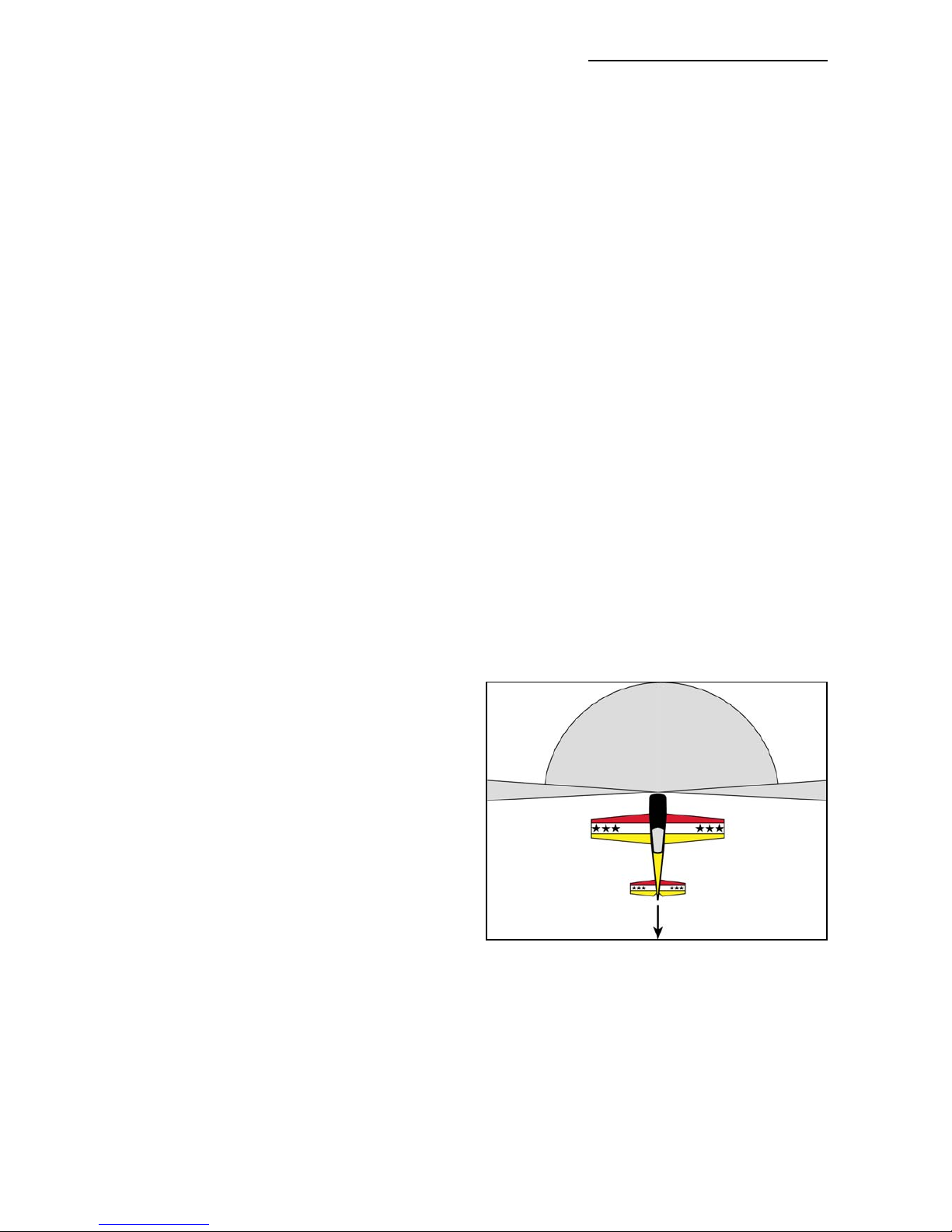
the first flights, doing fast vertical rolls and watching the
fuselage rolling in a perfect line. You can set it perfectly, this
is guaranteed.
The bottom slot needs some explanation, too. The cut line is exactly in the correct position so
that the aileron slides under the wing skin smoothly. If the cut was a few mm forward or back, it
would not work properly. So, make sure that the lip is not damaged, and that the aileron slides
under this lip perfectly. It will NOT lock at any time, as long as the lip is not damaged. If damage
occurs to the lip, you can cut off 2-3 mm, but you should NEVER need to cut off more than this.
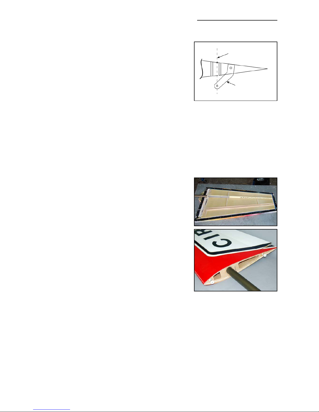
Make sure that the control horns are glued into the ailerons properly. The hole in the phenolic
horn for the quick-link needs to be exactly perpendicular to the hinge axis line, and in this
manual we show you a simple way to ensure that the horns in all pairs of control surfaces will be
identical, making it easy to set up your R/C for accurate flying manoeuvres.
The wings are already set-up with servo covers and hatch-
es for 2 servos per aileron, and we recommend a pair of
high-torque servos, like the JR D8411, in each wing. Our
servo covers and milled plywood mounts make both instal-
lation, and exchange if necessary, very quick and easy and
provide a rock solid servo mounting and linkage system.
The wings are attached to the fuselage with the 4 threaded
aluminium dowel anti-rotation pins, with 4 plastic nuts
inside the fuselage. If the aluminium dowels come loose in
the wing, the wing will slide outwards, away from the fuse-
lage, and the main spar tube will definitely break. So take
great care to inspect the glue joints of these anti-rotation
dowels in the wing REGULARLY. Excessive vibrations or
hard shocks can cause the glue joints to weaken or break.
Monitor these joints whenever you set up your plane. Never
forget to tighten the nuts inside the fuselage. Please DO
NOT modify these attachment dowels in any way, their per-
fect function is proven for many years.
The Fuselage:
The fuselage is also made in negative moulds, and is all constructed using TAVS technology. All
the loadbearing internal parts are installed during manufacture, to ensure accurate location and
reduce your assembly time. The fibreglass tubes in the wings to receive the wing spar tube, the
stab spar tubes, and the holes and reinforcement plates for the anti-rotation dowels, are already
installed. There is no need to even check the incidences - you can be assured that these are
already set in the moulds so that no adjustment is necessary.
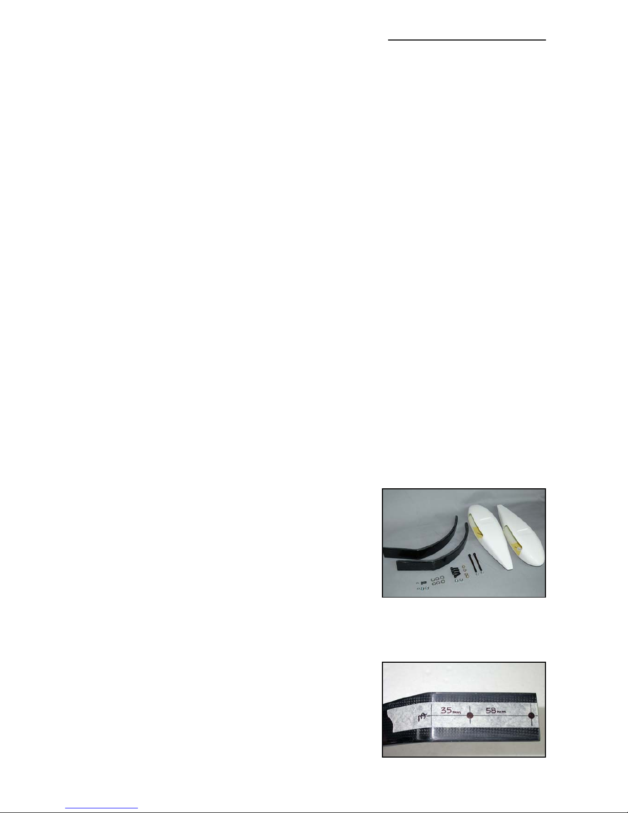
The landing gear mount is strong and doesn’t need any extra reinforcement. The fuselage is
extremely light weight, and the gear loads need to be led into the structure gently. No glue joint
needs to be stronger than the materials that it is attached to, as it would just result in increased
weight for no advantage. The landing gear is a fairly flexible design, which works very much like
5
Centreline of hinge axis
Phenolic control horn
Table of contents
Other Composite-ARF Aircraft manuals