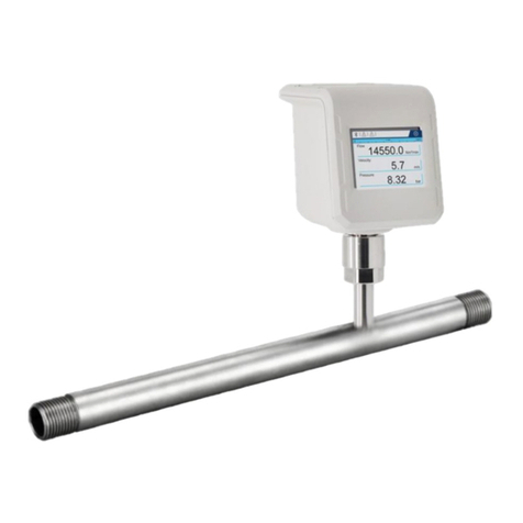
Compressed Air Alliance FLP User manual

www.compressedairalliance.com 1
User Manual
Flow Meter –
Pitot Tube
(Insertion)
Model: FLP

www.compressedairalliance.com 2
Flow Meter –Pitot Tube (Insertion Style) User Manual v1.1
Table of Contents
Notices...........................................................................................................................................3
Warnings .......................................................................................................................................3
About Flow Meters .......................................................................................................................5
Specifications................................................................................................................................6
Flow Meter Pack ...........................................................................................................................8
Installation Overview ...................................................................................................................9
Installation –Mechanical...........................................................................................................10
Installation –Electrical ...............................................................................................................20
Using the Display........................................................................................................................22
Setting Up the Flow Meter.........................................................................................................24
Data Logging...............................................................................................................................32
Screen Shot.................................................................................................................................34
Warranty......................................................................................................................................35
Calibration...................................................................................................................................35
Trouble Shooting........................................................................................................................36
Commissioning Report ..............................................................................................................39

Flow Meter –Pitot Tube (Insertion Style) User Manual v1.1
www.compressedairalliance.com 3
Notices
Please read this manual in full and
carefully observe the notes and
instructions before and during
installation, operation and maintenance.
The manufacturer cannot be held liable
for any damage which occurs as a result
of noncompliance with this manual.
Do not tamper with device. Should the
device be tampered with in any manner
other than a procedure which is
described and specified in this manual,
the warranty is cancelled and the
manufacturer is exempt from liability.
The product is designed exclusively
for the described application. Use of
this product in conditions not specified
in this manual or, contrary to the
instructions provided by the
manufacturer, is considered improper
handling of the product and will void
your warranty. The manufacturer will
not be held liable for any damages
resulting from improper use of the
product.
This manual should be read carefully by
relevant personnel and the end user.
This manual should be kept with the
product and be made available as
needed. Once you install or use the
product, you accept that you have
read, understood and complied with
this manual.
Compressed Air Alliance endeavours to
make the content of this manual correct,
but is not responsible for omissions or
errors and the consequences caused. In
case of any doubts or questions
regarding this manual or the product,
please contact Compressed Air Alliance.
Warnings
Ignoring the warnings can lead to
serious injury and/or cause damage!
When handling, operating or carrying
out maintenance on this product,
personnel must employ safe working
practices and observe all local health &
safety requirements and regulations.
Improper operation or maintenance of
this product could be dangerous and
result in an accident causing damage to
machinery or injury or death.
The manufacturer cannot anticipate
every possible circumstance which may
represent a potential hazard. The
warnings in this manual cover the most
common potential hazards and are
therefore not all-inclusive. If the user
employs an operating procedure, an
item of equipment or a method of
working which is not specifically
recommended by the manufacturer they
must ensure that the product will not be
damaged or made unsafe and that there
is no risk to persons or property.
NEVER CHANGE ORIGINAL
COMPONENTS WITH ALTERNATIVES.

Flow Meter –Pitot Tube (Insertion Style) User Manual v1.1
www.compressedairalliance.com 4
Compressed Air
Safety
Any contact with quickly escaping air
or bursting parts of the compressed
air system can lead to serious injuries
or even death.
•Do not exceed the maximum
permitted pressure.
•Only use pressure rated
installation materials and parts.
•Avoid getting hit by escaping air
or bursting parts.
•The system must be pressure-less
during maintenance work.
Electrical Safety
Any contact with energised parts of
the product, may lead to an electrical
shock which can lead to serious
injuries or even death. The user shall
take all measures necessary to protect
against electrical shock.
Consider all regulations for electrical
installations.
The system must be disconnected
from any power supply during
maintenance work.
Any electrical work on the system is
only allowed by authorised qualified
personal.
Storage and transportation
•Make sure that the transportation
temperature of the sensor is
between -10°C to 60°C (14°F to
140°F).
•Please make sure that the storage
temperature of the sensor is
between -10°C to 50°C (14°F to
122°F) and the humidity is <90%,
no condensation. Avoid direct UV
and solar radiation during
storage.
Cleaning
If you need to clean the sensor it is
recommended to use a clean, dry
cloth. For stubborn marks, use
distilled water or isopropyl alcohol
only.
Please note: contamination on the
sensor tip will affect calibration and
accuracy of the sensor. Removal of the
contamination may not fix the issue.
Disposal
Electronic devices are recyclable
material and do not belong in the
household waste. The product,
accessories and its packing material
must be disposed according to local
statutory requirements.

Flow Meter –Pitot Tube (Insertion Style) User Manual v1.1
www.compressedairalliance.com 5
About Flow Meters
Flow meters are very popular for
measuring compressed air and gas
systems. They can provide real time
information to help keep your system
under control and highlight any
unusual activity.
Benefits of monitoring flow include:
•Improve system efficiency
•Reduce system maintenance
•Reduce operating and energy
costs
•Increase system understanding
and operation
•Identify changes in system
performance
•Identify non-productive air
demand and leakage
•Identify peak and average
demand
Types of Flow Meters
There are a variety of flow meter
technologies including thermal mass,
pitot tube, vortex and venturi. In
compressed air and gas systems it is
important to avoid creating pressure
drops or restrictions that will decrease
system performance and increase
operating costs. Examples of flow
meters that cause pressure drops are
differential pressure plate, vortex and
venturi meters.
Pitot Tube Flow Meters
Pitot tube flow meters are ideally
suited to wet, dirty and high velocity
gases.
The sensor measures upstream
dynamic pressure and downstream
static pressure. The pressure
differential is a measure of the velocity
and flow rate.
Compressed Air Alliance’s pitot tube
flow meter has an extremely sensitive
differential pressure measurement
which allows the sensor to be used
over a wide flow range. The patented
anti condensation technology enables
the sensor to be used under saturated
conditions and ensures the sensor will
perform stable accurate
measurements for years to come.
Thanks to the online auto-calibration
technology, high reliability, long-term
measurement and accuracy can be
guaranteed.
Pitot flow meters are widely used in
industrial processes, chemical,
petrochemical, power engineering,
etc.
Pitot Tube flow meters are ideal for
both temporary or permanent
installations.

Flow Meter –Pitot Tube (Insertion Style) User Manual v1.1
www.compressedairalliance.com 6
Specifications
Pitot Tube Flow Meter - Insertion
Technology
Anti-condensation
Dryer Type
Air, Argon, Carbon Dioxide, Helium, Hydrogen, Natural
Gas, Nitrogen, Nitrous Oxide, Oxygen
Gases
Wet and dry gas, High velocities
Accuracy
Flow: ±(1% reading + 0.3% full scale)
Pressure: ±0.5% full scale
Accuracy is affected by the installation location, on-site conditions
and contaminants such as oil, high humidity or other impurities
Measurement Ranges
Flow Measurement
5 –300 Ns/m
17 to 984 ft/sec
Pressure Measurement
0 to 16 bar (232 psi)
Gas Temperature
Measurement
-40°C to +150°C
40°F to +302°F
Outputs
Output
Analog: 4 to 20mA (4-wire, Isolated) / Pulse output
Digital: RS485 Modbus / RTU
Output Signals
Flow, mass flow, consumption, pressure and temperature
Power
Power Supply
18 to 30V / 6.5W@24V
Anti Condensate Power Up
18 to 30V / 24W@24V
Electrical Connection
2 x 5 pin M12, female
EMC
According to IEC 61326-1
Display & Data Logger
Display
2.8” LCD with touch panel
Data Logger
10,000,000 samples
Sampling Rate
> 10 samples / second

Flow Meter –Pitot Tube (Insertion Style) User Manual v1.1
www.compressedairalliance.com 7
Pitot Tube Flow Meter - Insertion
Other Information
Bi-directional
No
Pipe Size
DN20 to DN300
Shaft Lengths
250 mm or 400 mm
9.8” or 15.7”
Process Connection
ISO G1/2" thread
Ambient Temperature
-20°C to +60°C
-4°F to +140°F
Installation Type
Permanent or temporary installation
Calibration Frequency
Every 2 years
Warranty Period
12 Months
Reference Conditions
20°C, 1bar(a), ISO1217 (Programmable)
Flow Range
Pipe Size
Flow Range (Nm3/h)
Flow Range (cfm)
DN
ID (mm)
Min Flow
Max Flow
Min Flow
Max Flow
25
25
8.8
530
5
312
32
32
14.5
868
9
511
40
40
22.6
1,357
13
798
50
50
35.3
2,120
21
1,247
65
65
59.7
3,583
35
2,108
80
80
90.5
5,428
53
3,193
100
100
141.4
8,482
83
4,990
125
125
220.9
13,253
130
7,797
150
150
318.1
19,085
187
11,228
200
200
565.5
33,929
333
19,962
250
250
883.6
53,014
520
31,190
300
300
1,272.3
76,340
749
44,913

Flow Meter –Pitot Tube (Insertion Style) User Manual v1.1
www.compressedairalliance.com 8
Flow Meter Pack
Each flow meter pack comes with:
✓1 x Pitot Tube Flow Meter –Insertion style, configured for your gas type.
✓1 x Adjustment tool
Optional Accessories
The following accessories are available for the flow meter. Talk to your local dealer or
Compressed Air Alliance or pricing.
CALMS –Cloud-based Data
Acquisition and Analysis software
Data Cables
Insertion Style
Pitot Tube
Flow Meter
Adjustment tool
PLUS

Flow Meter –Pitot Tube (Insertion Style) User Manual v1.1
www.compressedairalliance.com 9
Installation Overview
Step 1 –Find a suitable section of pipe
•The sensor must be installed vertically or horizontally
•The sensor must be installed away from bends, edges, seams, changes in
pipe size and other obstructions
•Do NOT install the sensor upside down
Step 2 –Install connection point, eg ball valve or nipple
Step 3 –Fit flow meter
Step 4 –Align sensor with direction of gas flow
Step 5 –Wire the sensor (see ‘Installation –Electrical’)
Step 6 –Set sensor settings:
•Inner Pipe Diameter
•Unit of Measurement
•Communication settings (RS485 or Analog)
•Optional –Confirm other sensor settings
Step 7 (optional) –Connect the sensor to your SCADA or energy management
system
Step 8 –Fill out the Commissioning Report (last page of this manual)
Tools and Equipment needed for installation
(not included with Flow Meter Pack)
Ball Valve
(optional)
Screw Driver
Wrench /
Spanner
Thread Tape /
Sealant

Flow Meter –Pitot Tube (Insertion Style) User Manual v1.1
www.compressedairalliance.com 10
Installation –Mechanical
WARNING! Incorrect installation can damage the sensor or cause it to work
incorrectly.
Notes
•You need to maintain a minimum flow velocity of 5 Nm/s (17 ft/sec) for the
pitot tube to work correctly. Below this minimum velocity, the flow meter
reading will be zero.
•Before installing the sensor, make sure it is rated for your system (refer to
the “Specifications” section).
oUse of the product outside specified ranges or operating parameters can
lead to malfunctions and may damage the product or system.
•Do not use this product in explosive areas.
•Close attention should be paid to the installation location and contamination
levels to ensure accuracy is maintained.
•The flow meter is not bidirectional. When installing and using the flow meter,
please pay attention to the direction of air flow and the alignment of the sensor.
The direction is indicated on the housing.
•The sensor is for indoor use only. If installed in an outdoor installation, the
sensor must be protected from sun and rain.
•Only use pressure rated materials and parts when installing and maintaining
the product.
•Do not disassemble the product.
•Please observe local and national regulations before/during installation and
operation.
•The product must be installed properly and calibrated regularly, otherwise it
may lead to inaccurate measurements.

Flow Meter –Pitot Tube (Insertion Style) User Manual v1.1
www.compressedairalliance.com 11
Step 1 –Find a suitable section of pipe
✓at 90° to the pipe, +/- 15° (ie within 75° to 105° of vertical).
✓vertically or horizontally,
✓away from bends, edges, seams, changes in pipe size and other obstructions,
Make sure the insertion location has enough room around the pipe to install the
sensor.
Install vertically to pipe
Correct Installation
75°
105°
Horizontal (0°)
✓
Vertical (90°)
Sensor is within ±15° of
vertical
Sensor is not
vertical
✓
✓
✓
Sensor installed
at 90° to the pipe
✓
Sensor can be installed in wet gas
or on the outlet of a compressor

Flow Meter –Pitot Tube (Insertion Style) User Manual v1.1
www.compressedairalliance.com 12
Incorrect Installation
Do NOT install the sensor upside down or at too much of an angle. This can result in
water accumulating in the shaft or head of the sensor. This can damage the sensor
and void the warranty
Choose insertion location, away from obstacles
To achieve and maintain the accuracy stated in the technical data, the sensor must
be inserted away from bends, edges, seams, curve, changes in pipe size, control
valves, etc.
For best results, choose a long, absolutely straight, section of pipe that is free of
obstructions.
Pipe obstructions (eg bends, edges, seams, curves, changes in pipe size, control
valves, etc) change the velocity of compressed air / gasses and/or create turbulence
near the obstruction. Placing the sensor too close to the obstruction will result in
inaccurate readings.
Sensor installed
upside down
Sensor installed at
too much of an angle

Flow Meter –Pitot Tube (Insertion Style) User Manual v1.1
www.compressedairalliance.com 13
Notes
•Pay careful attention to the distance between the sensor’s inlet and outlet
sections and points of turbulence (eg bends, valves, etc). Make sure that the
insertion location has enough straight pipe on either side of the sensor, as
shown in the diagrams on the next page.
•Obstructions can cause counter-flow turbulence as well as turbulence in the
direction of the flow.
•The diagrams below shows the minimum distances (in multiples of pipe
diameters (DNs)) that the sensor must be installed away from bends, changes in
pipe size and other obstructions.
Correct Installation
✓
✓
✓
✓
✓
✓
DN = Pipe Diameter

Flow Meter –Pitot Tube (Insertion Style) User Manual v1.1
www.compressedairalliance.com 14
Examples
•To install a flow meter near 2 x 90°
bends, you need at least 30 DN of space
(25 DN on the inlet side + 5 DN on the
outlet side, see diagram on previous
page)
•Only 20 DN is available.
•Therefore the sensor should not be
installed in this location
Available Space
•To install a flow meter near a
control valve or pressure regulator,
you need at least 55 DN (50 DN on
inlet side and 5 DN on outlet side,
see diagram on previous page)
•This section of pipe has 65 DN on
the inlet side and 5 DN on the
outlet side
•Therefore the sensor can be
installed in this location
Available Space
70 x DN
65 x DN
✓
A flow sensor will be installed on a section of pipe,
just after a bend (as shown in the diagram on the
left). The pipe has a DN of 50 (ie, it’s a 2 inch or 50
mm pipe).
Therefore the sensor must be installed:
•
Inlet side: 20 x DN from the bend
= 20 x 2” = 40” or
= 20 x 50mm = 1,000mm = 1 meter
•Outlet side: 5 x DN from any other obstruction
= 5 x 2” = 10” or
= 5 x 50mm = 250mm
Minimum spacing on
inlet and outlet sides
for DN 50
1 meter
or 40”
250 mm
or 10”

Flow Meter –Pitot Tube (Insertion Style) User Manual v1.1
www.compressedairalliance.com 15
Step 2 –Install connection point
To install the sensor, you need a connection point to the pipe, eg a ball valve or a
nozzle or nipple. The thread must be G 1/2".
Use of a ball valve is optional - You do not need to use a valve to install the sensor.
However, using a valve will make removing the sensor easier (eg when you need to
remove the sensor for calibration).
If installing a ball valve, you can use a hot tap drill and clamp to create a connection
point on pressurized or unpressurised pipes. See the Compressed Air Alliance
website for information on hot tap drills and clamps.
Ball Valve
Welded nipple on pipe
OR

Flow Meter –Pitot Tube (Insertion Style) User Manual v1.1
www.compressedairalliance.com 16
Step 3 - Fit Flow meter
•Place O-Ring on sensor shaft gland nut.
•Screw the sensor into the connection point.
•If using a ball valve, open the valve.
Place O-Ring on sensor
shaft gland nut
Ball Valve
(Optional)
Sensor shaft gland
nut

Flow Meter –Pitot Tube (Insertion Style) User Manual v1.1
www.compressedairalliance.com 17
•Use the depth scale on the sensor shaft to place the tip of the sensor in the
middle of the pipe.
•Once the tip is in the centre of the pipe, tighten the gland nut to hold the sensor
in place.
The Insertion Depth = x + y =
𝑂𝐷
2+ y.
Where OD = outer diameter of pipe and Y = ball valve height.
Example
A flow meter is being installed in a cooper tube
with a DN of 100. This equates to an outer
diameter (OD) of 100 mm. The ball valve is
87 mm high.
The Insertion Depth = OD/2 + y where y =
height of the ball valve.
Therefore, the Insertion Depth =
100 mm / 2 + 87 mm = 137 mm.
Push in sensor until
Insertion Depth = 137mm

Flow Meter –Pitot Tube (Insertion Style) User Manual v1.1
www.compressedairalliance.com 18
Correct Installation
The sensor tip must be in the center of the pipe / tube.
Incorrect Installation
Note: Inaccurate measurement may occur if the sensor is installed incorrectly.
Sensor tip not in
centre of pipe
Sensor tip too
high
Sensor tip too
low
Sensor tip is in the
center of the pipe

Flow Meter –Pitot Tube (Insertion Style) User Manual v1.1
www.compressedairalliance.com 19
Step 4 –Align sensor with the direction of flow
The flow meter is not bidirectional. When installing and using
the flow meter, please pay attention to the direction of air flow
and the alignment of the sensor.
The direction is flow is marked by 4 green arrows on the back of
the sensor and underneath the sensor.
Use the alignment tool to
align the sensor with the
pipe. Ensure the arrows
on the sensor match the
direction of flow.
Correct Installation
The sensor is aligned in the same direction as the gas flow.
Incorrect Installation
Note: Inaccurate measurement may occur if the sensor is installed incorrectly.
Direction of gas flow
Sensor alignment
Direction of gas flow
Sensor alignment

Flow Meter –Pitot Tube (Insertion Style) User Manual v1.1
www.compressedairalliance.com 20
Installation –Electrical
WARNING! Incorrect wiring can damage the sensor or cause it to work
incorrectly.
Notes:
•Do not screw the M12 connector using force, otherwise it may damage the
connection pins.
•Always check the M12 connectors to make sure they are wired correctly.
•Consider all local and national safety requirements and regulations for electrical
installations.
•The system must be disconnected from any power supply during
installation and maintenance work.
•Any electrical work on the system is only allowed by authorised and qualified
personal.
The flow sensor has two x 5 pin M12 connector plugs - “A” and “B”. Cables are
connected to the sensor through the M12 connector plugs.
•Connector Ais used for power and Modbus
•Connector Bis used for 4-20mA and pulse
Connector B
4-20mA & Pulse
Connector A
Power & Modbus
Micro USB
Connection
Table of contents
Other Compressed Air Alliance Measuring Instrument manuals
Compressed Air Alliance
Compressed Air Alliance FLP10000 Series User manual

Compressed Air Alliance
Compressed Air Alliance POM200 User manual

Compressed Air Alliance
Compressed Air Alliance POM100 User manual
Compressed Air Alliance
Compressed Air Alliance Vortex FLV User manual

Compressed Air Alliance
Compressed Air Alliance POM200x00 User manual

Compressed Air Alliance
Compressed Air Alliance POM200 User manual

Compressed Air Alliance
Compressed Air Alliance POM400 User manual

Compressed Air Alliance
Compressed Air Alliance FLT User manual
Compressed Air Alliance
Compressed Air Alliance FLF User manual
Compressed Air Alliance
Compressed Air Alliance ROG User manual