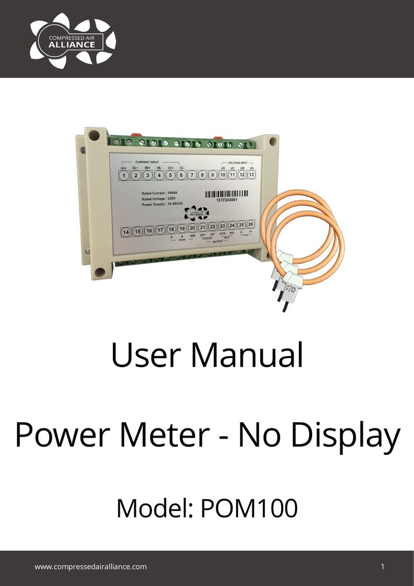
Compressed Air Alliance POM200x00 User manual

sales@compressedairalliance.com
www.compressedairalliance.com 1
User Manual
Power Meter with Display
Model: POM200x00

Multi-function Power Meter with Display User Manual v1.0
Compressed Air Alliance 2
www.compressedairalliance.com
Table of Contents
Table of Contents.........................................................................................................................................2
Notices ..........................................................................................................................................................3
Multi-Function Power Meter ......................................................................................................................4
Why should you monitor power? ....................................................................................................................... 4
This power meter is best suited to..................................................................................................................... 4
Key Features .......................................................................................................................................................... 4
Installation Requirements ................................................................................................................................... 4
Dimensions ............................................................................................................................................................ 4
Specifications ...............................................................................................................................................5
General Specifications.......................................................................................................................................... 5
Displaying Data ..................................................................................................................................................... 7
Modbus RS485....................................................................................................................................................... 8
Certificates ............................................................................................................................................................. 8
Port Definition ....................................................................................................................................................... 9
Wiring Diagrams ........................................................................................................................................10
Mounting Diagram.....................................................................................................................................15
Operating Instructions..............................................................................................................................16
Viewing Data ..............................................................................................................................................17
System Settings..........................................................................................................................................20
Calibration..................................................................................................................................................24
Firmware & Serial Number.......................................................................................................................26
Warranty and Help ....................................................................................................................................27
Appendix –Communication Protocol......................................................................................................28

Multi-function Power Meter with Display User Manual v1.0
Compressed Air Alliance 3
www.compressedairalliance.com
Notices
Please read this user manual in full and carefully
observe the notes and instructions before and
during installation, operation and maintenance.
The manufacturer cannot be held liable for any
damage which occurs as a result of non-
observance or noncompliance with this user
manual.
Should the device be tampered with in any
manner other than a procedure which is
described and specified in this manual, the
warranty is cancelled and the manufacturer is
exempt from liability.
The device is designed exclusively for the
described application.
This user manual should be read carefully by
the technician / qualified personnel and the end
user. This manual should be kept with the
power meter and made available to relevant
personnel. In case of any obscurities or
questions, regarding this manual or the product,
please contact Compressed Air Alliance.
Electrical Safety
Users should be suitably qualified, licensed and
experienced to use this product. Incorrect use
or installation could result in serious injury or
death. Compressed Air alliance is not liable for
any injury or incident occurring from using this
product.
Installing the Power Meter
and Maintenance Work
•The system must be disconnected from any
power supply during installation and
maintenance work.
•Any electrical work on the system is only
allowed by authorised qualified personal.
•The product should be maintained and
checked for faulty wiring on a regular basis.
•Do not use isopropyl alcohol to clean the
power meter.
Note: The power meter must be installed
properly and maintained. Incorrect installation
or maintenance may void the warranty and
result in:
•electric shock or electrocution
•damage to the power meter or other
equipment
•wrong measurement values, which can lead
to wrong results.
Using the Power Meter
•The power meter is not to be used in
explosive areas.
•Do not exceed or undercut the permitted
operating parameters.
•Do not exceed or undercut the permitted
storage parameters.
•See Specifications section for permitted
operating and storage parameters.
Note: any operation exceeding maximum or
minimum permitted parameters can lead to
malfunction and may lead to damage on the
power meter or the system. It may also void the
warranty.
Disposing of the Power Meter
Electronic devices are recyclable material and
do not belong in the household waste. The
power meter, accessories and its packing
material must be disposed according to your
local statutory requirements.

Multi-function Power Meter with Display User Manual v1.0
Compressed Air Alliance 4
www.compressedairalliance.com
Multi-Function Power Meter
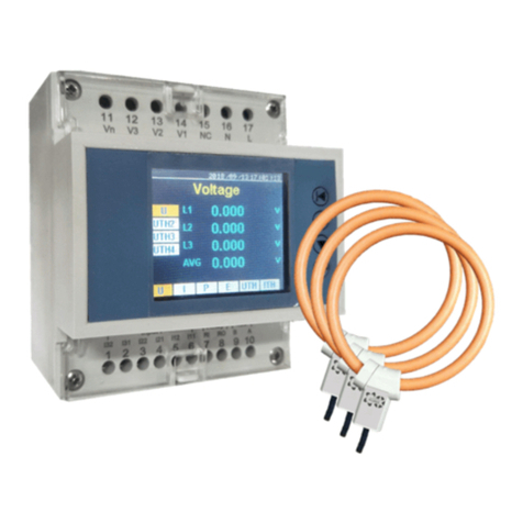
This multi-function three phase power meter
with Modbus/RTU output is simple to install and
easy to configure directly through the built in
display. The power meter can be connected to
your data acquisition system for long term
monitoring.
The power meter can be installed on mains
supply and can be used for sub metering
individual equipment or sub loads.
Why should you monitor
power?
Monitoring power can help you:
•Reduce operating and energy costs
•Improve understanding of energy usage (eg
spikes, variation, usage)
•Identify phase and voltage issues
•Identify power factor and harmonic issues
•Compare and challenge your energy bill
•Improve efficiency and reduce waste
•Monitor your mains power supply usage and
quality
•Monitor individual equipment usage or sub
system loads
This power meter is best
suited to
•3 phase or single phase measurements
•Where a built-in display is required
•Permanent installations
Key Features
•Measure voltage, amps, kilowatts, power
factor, kilowatt hours, kilovolt Amps (kVa)
and harmonics
•Built in display for easy reading and
configuration
•DIN rail mounting
•Modbus/RTU output
•Easy to install rogowski coil current
transducers
•Can be installed on mains supply
•Can be used for sub metering individual
equipment or sub loads
Installation Requirements
Installing power meters is not difficult but
should be done by suitably qualified and
experienced technicians. Some knowledge of
MODBUS communications is required to
connect the power meters to your network.
Dimensions
95 mm

Multi-function Power Meter with Display User Manual v1.0
Compressed Air Alliance 5
www.compressedairalliance.com
Specifications
General Specifications
Power Meter Details
Type
Multi-function power meter
Applications
Power analysis
Tariff meter
Mounting
Din Rail, clip on
Poles description
3PH4W 3PH3W
1PH2W (L-N) 1PH2W (L-L) 1PH3W (L-L-N)
Available clamp sensors
Rogowski coil - 500A or 1,000A or 3,000A
Sampling rate
8,000 samples per second
Harmonic
52th Max
Power meter dimensions
76 mm L x 95 mm W x 71 mm D
Weight
212 grams
Colour
White
Installation Type
Permanent installation or temporary installation
Contractual warranty
12 months
Measurement Ranges
Measured voltage
100V to 500V AC
Frequency
50/60Hz
Accuracy
Note: The accuracy of the
power meter is affected by the
quality of installation. On-site
conditions such as oil, high
humidity or other impurities
can also affect the accuracy of
the power meter
Current
0.5% from 1% to 120%
(manufacturer doesn’t ensure accuracy when
<10A)
Rated current
500A (0.5% from 10A to 600A)
3000A (0.5% from 30A to 3600A)
10kA (0.5% from 100A to 12kA)
Rogwoski coil
specification
85mV/kA@50Hz±0.5%
Voltage
0.2% from 100V to 500V (L-L and L-N)
Power factor
±0.005 from 10% to 120%
Active/Apparent Power
IEC62053-22 Class 0.5
Reactive power
IEC62053-21 Class 2
Frequency
0.01% from 45 to 65Hz
Active energy
IEC62053-22 Class 0.5s
Reactive energy
IEC62053-21 Class 2

Multi-function Power Meter with Display User Manual v1.0
Compressed Air Alliance 6
www.compressedairalliance.com
Power
Power supply
85 to 265 V AC/DC, 3W
Input
Input type
External CT (333mV only) or External Rogowski coil
Primary current range
Adjustable from 0.1A to 9999A
Measurement input range
1/225mV-333mV
Permissible overload
600mV for 10s/hours
Output
Output parameters
Voltage, Amps and Kilowatts for each phase, power factor, reactive power
(kVa), total Kilowatts, Kilowatt hours and electrical system harmonics
Communication
RS485 Modbus / RTU
Connection
Terminal strip
Screw terminals 2.5mm2, interval 5.08mm
Digital Output
1× digital output (2 ports) (controlled by Modbus)
2.5kVrms insulation
Maximum Switching Power:
10A, 277VAC
10A, 28VDC
Environmental Conditions
Operating temperature
-25°C to +55°C
-13°F to +131°F
Storage temperature
-40℃to +85℃
-40°F to +185°F
Humidity rating
5% to 95% RH at 50℃ (non-condensing)
Pollution degree
2: Normally only nonconductive pollution occurs. Temporary conductivity
caused by condensation is to be expected.
Overvoltage category
III, for distribution systems up to 277/480VAC
Dielectric withstand
As per IEC61010-1, Doubled insulated front panel display
Altitude
3000m Max
IP degree of protection
IP20 conforming to IEC 60629
Alarm
Setting
Voltage and current, each phase
Output form
Buzzer, Relay

Multi-function Power Meter with Display User Manual v1.0
Compressed Air Alliance 7
www.compressedairalliance.com
Displaying Data
Display
Display
2 inch TFT colour screen
Display
Display size
39 mm x 32 mm
Display size
Display resolution
220 x 170 dots
Display resolution
Maximum value measured
Parameter
Range
Resolution (number of decimal points)
Voltage
0.001 V
999.9 V
999.9 kV
999.9 MV
0.1
Current
999.9 A
999.9 kA
0.1
Power
999.9 kW
999.9 MW
0.1
Power factor
0.999
0.001
THD
99.9%
0.1%
Energy
999.9 Wh
999.9 kWh
999.9 MWh
999.9 GWh
0.1
Instantaneous rms Values
Voltage
U, UTH2, UTH3, UTH4 (Per Phase, AVG)
Current
I, ITHD2, ITHD3, ITHD4 (Per Phase, AVG)
Power
P, FQ, S, PF (Per Phase, SUM)
Energy
EP, EFQ, ES, Freq (Per Phase, SUM)
over 999.9GWh, value resets
UTHD (%)
UTHD, THD2, THD3, THD4 (Per Phase, AVG)
ITHD (%)
ITHD, THD2, THD3, THD4 (Per Phase, AVG)
Update Rate
Data acquisition rate
400ms
Display update rate
0.5s
Energy storage interval
10mis (default)
(prevent losing energy when power off)
Calibration
Current
Per phase, all
Voltage
Per phase, all

Multi-function Power Meter with Display User Manual v1.0
Compressed Air Alliance 8
www.compressedairalliance.com
Power factor
Per phase, all
Energy
Reset to “0” EP, EQ, ES all phase
Modbus RS485
Communication
Transmission mode
RS485 port, Half duplex
RS485 link
2 wires
Communication protocol
MODBUS RTU
Settings
Communication address
1 to 247 (default 1)
Baud rate
(communication speed)
1200 to 57600 baud (default 9600)
Parity
Even (default), Odd, None
Data Bit
8
Stop bit
1
Certificates
EMC
Electrostatic discharge
Level IV (IEC61000-4-2)
Immunity to radiated fields
Level III (IEC61000-4-3)
Immunity to fast transients
Level IV (IEC61000-4-4)
Immunity to surge
Level IV (IEC61000-4-5)
Conducted immunity
Level III (IEC61000-4-6)
Immunity to power frequency
magnetic fields
0.5mT (IEC61000-4-8)
Conducted and radiated
emissions
Class B (EN55022 )
Standard compliance
EN 62052-11, EN61557-12, EN 62053-21, EN 62053-22, EN 62053-23, EN 50470-1, EN 50470-3,
EN 61010-1, EN 61010-2, EN 61010-031

Multi-function Power Meter with Display User Manual v1.0
Compressed Air Alliance 9
www.compressedairalliance.com
Port Definition
Port Number
Port Name
Port Function
Remarks
1
I31
A-phase current input positive
A-phase current
Current (I) Input
2
I32
A-phase current input negative
3
I22
B-phase current input positive
B-phase current
4
I21
B-phase current input negative
5
I12
C-phase current input positive
C-phase current
6
I11
C-phase current input negative
7
RI
Relay Input
Relay
8
RO
Replay Output
9
D1 (B)
R485 B
R485 Communication
10
D0 (A)
R485 A
11
Vn
N-phase voltage input
Voltage (V) input
12
V3
C-phase voltage input
13
V2
B-phase voltage input
14
V1
A-phase voltage input
15
NC
Not connected
Not connected
16
V+ (N)
Power (-)
Power 85-265 V AC/DC
17
V- (L)
Power (+)

Multi-function Power Meter with Display User Manual v1.0
Compressed Air Alliance 10
www.compressedairalliance.com
Wiring Diagrams
Before installing the power meter, make sure it is rated for your system (refer to Specification section).
WARNING:Incorrect wiring and installation can cause an electric shock, electrocution or
damage to the power meter or other equipment. It may also void the warranty.
Notes:
Rcoil*:Rogowski coil secondary output voltage can not be over 333mV rms.
CT^:CT must be voltage output, secondary output can not be over 333mV rms.
Circuit breaker: 500mA fuses and disconnect switch
VT primary fuses and disconnect switch
3PH4W no VT

Multi-function Power Meter with Display User Manual v1.0
Compressed Air Alliance 11
www.compressedairalliance.com
3PH4W with VT
3PH3W no VT

Multi-function Power Meter with Display User Manual v1.0
Compressed Air Alliance 12
www.compressedairalliance.com
3PH3W with VT
1PH3W

Multi-function Power Meter with Display User Manual v1.0
Compressed Air Alliance 13
www.compressedairalliance.com
1PH2W
Modbus Communication Wiring Diagram
Input & Output Wiring diagram

Multi-function Power Meter with Display User Manual v1.0
Compressed Air Alliance 14
www.compressedairalliance.com
Rogowski Coil Connection
Rogwoski coil specification 85mV/kA@50Hz±0.5%

Multi-function Power Meter with Display User Manual v1.0
Compressed Air Alliance 15
www.compressedairalliance.com
Mounting Diagram
Installation

Multi-function Power Meter with Display User Manual v1.0
Compressed Air Alliance 16
www.compressedairalliance.com
Operating Instructions
Interface
1. Date and Time
2. Data display
3. Measurement options, from left to right:
U (voltage), I (current), P (Power), E (Energy),
UTHD (harmonics voltage distortion), IHTD
(harmonics current distortion)
4. Secondary menu. Options vary depending on
which measurement option is selected.
5. Navigation Buttons
Navigation
Long press (press and hold) the up button
to move left
Long Press (press and hold) the down
button to move right
Short press the up button to move up
Short press the down button to move down
To select an item, short press Enter
Measurement Option Navigation
To move to the next measurement option (eg to
move from U to I), press and hold (long press) the
Down / Right button to move right. Short
press Enter to access the measurement
menu
To move to the previous measurement option
item (eg to move from E to P), press and hold (long
press) the Up / Left button to move left. Short
press Enter to access the measurement
menu
Secondary menu navigation
To move to the next secondary menu
item (eg to move from U to UTH2), short
press the Down / Right button to
move down.
Short press Enter to access the secondary
menu
To move to the previous secondary menu item
(eg to move from UTH4 to UTH3), short press the
Up / Left button to move up. Short press
Enter to access the secondary menu
Go to Main Menu or exit a screen
To go to the main menu or to exit a screen, press
the Menu / Quit button
2
1
4
3
5
Menu, Quit
Up, Left
Down, Right
Enter

Multi-function Power Meter with Display User Manual v1.0
Compressed Air Alliance 17
www.compressedairalliance.com
Viewing Data
Main Menu
Data: Go to the data screen to see measurement
values for voltage, current, harmonics, etc
Set: Set system information, eg time, comms
settings, password
Cal.: Calibrate voltage, current and power factor.
Reset energy values to zero
Info: View the power meter’s model number,
firmware version and serial number
To return to the main menu from any screen or
to exit a screen press the Menu / Quit
button
Data Screen
To view measurement data:
Step 1 - From the Main menu, press the Up or
Down buttons to move to the Data
Menu.
Step 2 - Click Enter to access the
measurement screens.
Measurement Menus
The measurement options (voltage, current,
power etc) are on the bottom of the screen.
To move between measurement options, (eg to
move from U to I or vice versa):
•Long press (press and hold) the Up or Down
buttons to move left or right
•Short press Enter to access the
measurement menu
Measurement Sub Categories
Each measurement option has a series
of sub-categories. These are shown on
the left hand side of the screen.
To move between measurement sub
categories (eg to move from U to UTH2 or vice
versa):

Multi-function Power Meter with Display User Manual v1.0
Compressed Air Alliance 18
www.compressedairalliance.com
•Short press the Up or Down
buttons to move up or down
•Short press Enter to access the secondary
menu
Measurement Values
Measurement values are shown in the center of
the screen.
Voltage (U)
Voltage measurement options, from top to
bottom:
•U(voltage)
•UTH2 (2 harmonics)
•UTH3 (3 harmonics voltage)
•UTH4 (4 harmonics voltage)
Current (I)
Current measurement options, from top to
bottom:
•I (current)
•ITH2 (2 harmonics current)
•ITH3 (3 harmonics current)
•ITH4 (4 harmonics current)
Power (P)
Power measurement options, from top to bottom:
•P (active power)
•FQ (reactive power)
•S(apparent power)
•PF (power factor)

Multi-function Power Meter with Display User Manual v1.0
Compressed Air Alliance 19
www.compressedairalliance.com
Energy (E)
Energy measurement options, from top to bottom:
•EP (active energy)
•EFQ (reactive energy)
•ES (apparent energy)
•ETF (Energy Tariff)
•Freq (frequency)
Sub Menu - Energy Tariff
Tariff selected by digital input. Logic relation
below:
DI2=0 & DI1=0 ETF1
DI2=0 & DI1=1 ETF2
DI2=1 & DI1=0 ETF3
DI2=1 & DI1=1 Not Available
Voltage Harmonics (UTHD)
UTHD menu options, from top to bottom:
•Uthd (total harmonics voltage distortion)
•THD2 (2 harmonics voltage distortion)
•THD3 (3 harmonics voltage distortion)
•THD4 (4 harmonics voltage distortion)
Current Harmonics (ITHD)
ITHD menu options, from top to bottom:
•Ithd (total harmonics current distortion)
•THD2 (2harmonics current distortion)
•THD3 (3harmonics current distortion)
•THD4 (4 harmonics current distortion)

Multi-function Power Meter with Display User Manual v1.0
Compressed Air Alliance 20
www.compressedairalliance.com
System Settings
Main Menu
Data: Go to the data screen to see measurement
values for voltage, current, harmonics, etc
Set: Set system information, eg time, comms
settings, password
Cal.: Calibrate voltage, current and power factor.
Reset energy values to zero
Info: View the power meter’s model number,
firmware version and serial number
To return to the main menu from any screen or
to exit a screen press the Menu / Quit
button
Set Menu
The System Settings screen allows you change
system information such as time, comms settings,
password, wire settings and alarms.
To access the System Setting screen:
Step 1 - From the Main menu, press the Up or
Down buttons to move to the Set
Menu.
Step 2 - Click enter to access the System
Settings.
System Setting Menu Options
•Wire: Set the Mode (eg 3PH3W or 1PH3W),
Vcon, Icon and Frequency
•Ratio: Set the CT, RCoil and VT ratios
•Comm: Set the communication settings
including address, baudrate and parity
•Harmonic: Set harmonics
•Password: Set Password
•Time: Set the system time and date
•Threshold: Set thresholds for min and max
voltage, min and max current. Set alarm.
Note: The default password is 1000
Table of contents
Other Compressed Air Alliance Measuring Instrument manuals
Compressed Air Alliance
Compressed Air Alliance FLF User manual

Compressed Air Alliance
Compressed Air Alliance POM100 User manual

Compressed Air Alliance
Compressed Air Alliance POM200 User manual

Compressed Air Alliance
Compressed Air Alliance POM400 User manual
Compressed Air Alliance
Compressed Air Alliance ROG User manual
Compressed Air Alliance
Compressed Air Alliance FLP User manual

Compressed Air Alliance
Compressed Air Alliance Vortex FLV User manual

Compressed Air Alliance
Compressed Air Alliance FLT User manual
Compressed Air Alliance
Compressed Air Alliance POM200 User manual

Compressed Air Alliance
Compressed Air Alliance FLP10000 Series User manual