Compressed Air Systems 7.5hp User manual

Introduction. Congratulations on the purchase of your new air compressor. The air compressor is precision
built from the nest materials using the nest state of the art design, and high tech engineering available today.
Quality, performance and trouble free operation will assure you a dependable supply of air power on demand
CAUTION READ THIS MANUAL CAREFULLY before operating or servicing this air compressor, to
familiarize yourself with the proper safety, operation, and standard operating procedures of this unit.
FAILURE TO COMPLY WITH INSTRUCTIONS IN THIS MANUAL COULD RESULT IN THE VOIDING OF YOUR
WARRANTY, AND PERSONAL INJURY, AND/OR PROPERTY DAMAGE. THE MANUFACTURER OF THIS AIR
COMPRESSOR WILL NOT BE LIABLE FOR ANY DAMAGE BECAUSE OF FAILURE TO FOLLOW THE INSTRUCTIONS
IN THIS MANUAL. By following the instructions and recommendations in this manual you will ensure a longer and
safer service life of your air compressor.
If you have questions or need clarication about this manual or your compressor call 800-531-9656
Do not operate compressor outdoors in wet weather
Check www.compressed-air-systems.com for most up to date manual and compressor service and technical information
Owners
Manual
5-15 HP Electric
Rotary Screw Compressors
Simplicity. It’s What We Do.
compressed-air-systems.com | 1-800-531-9656 | Fax 972-352-6364
Compressed Air Systems

SAFETY PRECAUTIONS AND WARNINGS
Listed are some, but not all safety precautions that must be observed with compressors and
compressed air systems. Failure to follow any of these warnings may result in severe personal injury,
death, property damage and/or compressor damage.
Air from this compressor will cause severe injury or death if used for breathing or food processing.
Air used for these processes must meet OSHA 29 CFR 1910 or FDA 21 178.3570 regulations.
This compressor is designed for use in the compression of normal atmospheric air only. No other gases, vapors or fumes
should be exposed to the compressor intake, nor processed through the compressor.
Disconnect all power supplies to the compressor plus any remote controllers prior to servicing the unit.
Relieve all pressure internal to the compressor prior to servicing.
Do not depend on check valves to hold system pressure.
A properly sized safety valve must be installed in the discharge piping ahead (upstream) of any shut-o valve (block valve),
heat exchanger, orice or any potential blockage point. Failure to install a safety
relief valve could result in rupturing or explosion of some compressor or safety component.
Do not change the pressure setting of the safety relief valve, restrict the function of the
safety relief valve, or replace the safety valve with a plug.
Over pressurization of some system or compressor component can occur, resulting in severe personal injury, death and
property damage.
Never use plastic pipe, rubber hose, or soldered joints in any part of the compressed air system.
Failure to ensure system compatibility with compressor piping is dangerously unsound.
Never use a ammable or toxic solvent for cleaning the air lter or any parts.
Do not attempt to service any part while the compressor is operating.
Do not operate the compressor at pressures in excess of its rating.
Do not remove any guards while the compressor is operating.
Observe gauges daily to ensure compressor is operating properly.
Follow all maintenance procedures and check all safety devices on schedule.
Compressed air is dangerous, do not play with it.
Use the correct lubricant at all times.
Always wear proper safety equipment when using compressed air.
Always install compressor to all local applicable electric codes.
WARNING: Read all installation steps in install guide, and compressor package manual prior to
un-crating or installing compressor package. Failure to do so can result in personal injury or damage
to compressor package.
NOTICE: All compressor air receivers should be inspected by a certied pressure vessel technician
at least once per year, to check for leaks, weak points in the metal or any other deformity of the air
receiver. If at any time a receiver appears out of conformance with ASME/CRN certication or a
deformity is believed to have developed no matter how minor it may appear the tank should be
locked out of service immediately and replaced with a certied ASME/CRN certied air receiver
immediately before the compressor can be put back into service. The receivers should have a
general inspection weekly as part of normal service.
Compressed Air Systems, LLC 1-800-531-9656 Fax 972-352-6364 www.compressed-air-systems.com
5-15 HP Electric Rotary Screw Compressors

WARNING: Never apply air pressure to compressor crank case, always make sure crank case vent is clear
and free from obstructions. Adding pressure to the crank case can cause serious bodily injury or death.
WARNING: Always wear proper protective eyewear,, hearing protection and safety clothing when
working around the compressor package. No loose or baggy clothing should be worn around
compressor package at any time.
WARNING: On Electric motor powered air compressors make sure electrical system is up to National
Electric Code (NEC) prior to installing compressor system. Failure to install a compressor with a proper
NEC electrical system can cause personal injury, compressor package damage and void compressor
package warranty
NOTICE: To ensure full compressor tank warranty all tank mounted compressor packages must be
mounted on factory approved vibration isolation pads. A compressor should NEVER be installed while
still on or in its original packaging. Failure to properly install the compressor system with approved
vibration isolation pads will result in the compressor tank warranty being void.
WARNING: Compressed Air Systems compressors can operate at pressures from 0-250psi depending
on the compressor package design and build specications. Always verify that the system the
compressor is installed into can handle the maximum operational pressure the compressor. NEVER
install a compressor in a system that can not handle the compressors maximum operating pressure.
WARNING: Compressed air is extremely dangerous when not properly used or installed. Always make
sure a trained compressed air professional has looked over the air system prior to use. Improper
installation or use of compressed air can cause bodily injury or death. NEVER pressurize an object that
was not designed to be pressurized. Pressurizing objects not properly engineered for the maximum
operating pressure of the compressor system can cause bodily injury or death.
WARNING: Never operate a compressor in a moving vehicle or towable object in motion.
Doing so can damage the compressor, compressor drive components, or auxiliary parts on the com-
pressor package. Operating the compressor in a moving vehicle or towable object can cause serious
bodily injury or death.
WARNING: Check function of safety valves, weekly to insure proper function,
replace immediately if faulty or damaged.
WARNING: (Compressors Packaged with NEMA 7 Components)
Compressed Air Systems, LLC certies that the electric motor, electrical enclosure and
electrical conduit are rated for NEMA7/hazardous locations. (Only for applicable packages with
NEMA7 added components)
Air compressors have multiple moving parts and potential points of contact that could
create an ignition source. The compressor pumps are manufactured with ferrous metals and in some
cases multiple moving parts can come in contact with one another causing an ignition source.
Compressed Air Systems LLC does not guarantee this will not occur. Lack of maintenance or care can
result in conditions that could also cause ignition sources.
Compressed Air Systems, LLC only guarantees that the electric motor, electrical enclosure and
electrical conduit are rated for NEMA7 hazardous location. Compressed Air Systems LLC accept no
other responsibility for the rating of the package.
Compressed Air Systems, LLC 1-800-531-9656 Fax 972-352-6364 www.compressed-air-systems.com
5-15 HP Electric Rotary Screw Compressors

Descriptions
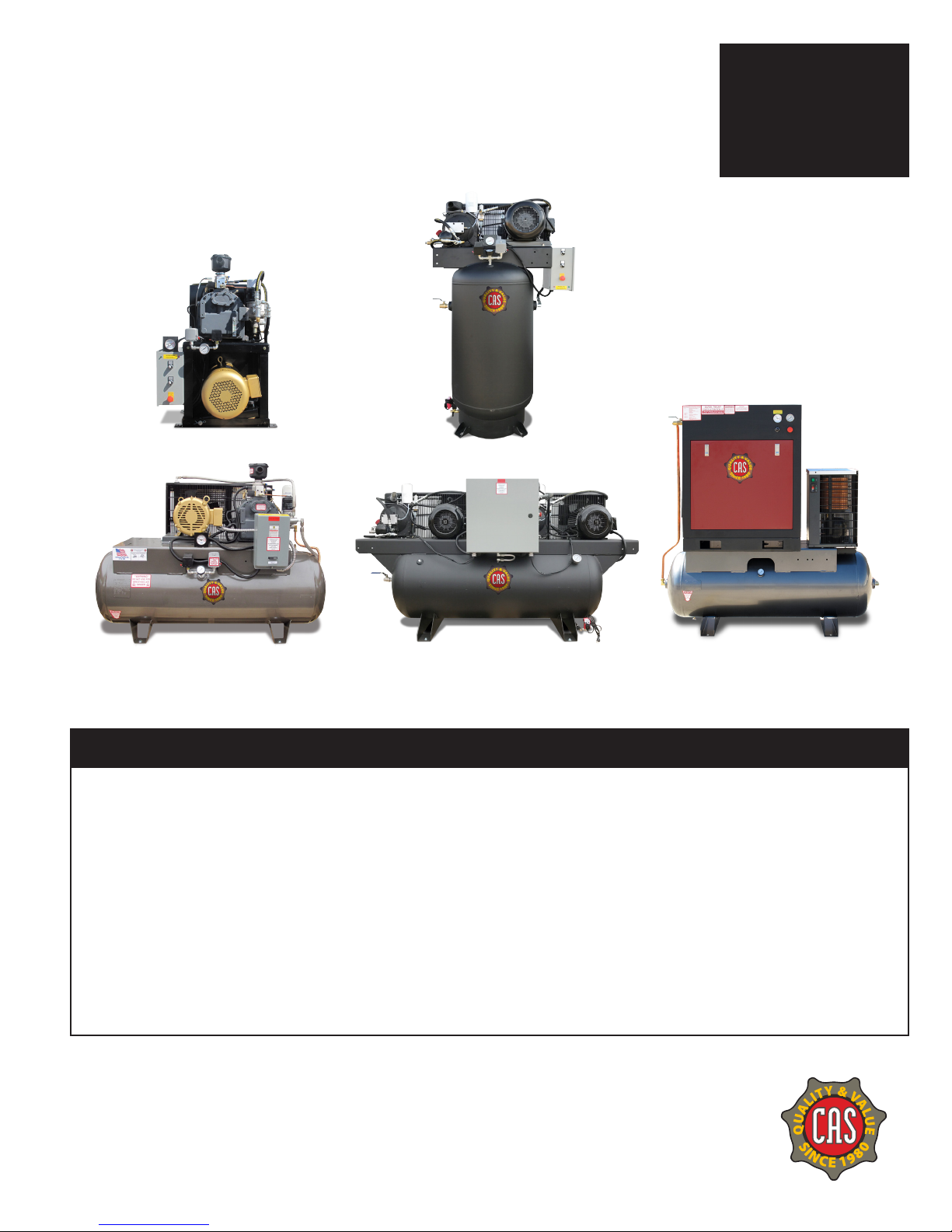
This Compressed Air Systems industrial rotary screw
compressor is an electric motor driven single stage
helical rotary screw compressor. It is sold as a complete
package mounted on a steel base. This unit can come
with options of being tank mounted, Enclosure
mounted or Enclosure tank mounted. The package
includes the compressor air end, electric motor, motor
controls, air intake system, cooling system, SMART
contact capacity control system, air/oil separator, and
instrumentation. Installation requires only electric
power and a service line.
This air compressor is a rotating piece of equipment
and should not be worked on or serviced while there is
power to the unit. You should always turn the power o
to the compressor unit before performing and
kind of service to the machine. If you have any questions
please contact the factory for clarications before
making any changes to the delivered state of the
compressor.
The owner, lesser, or operator of this compressor is hear
by notied and forewarned that any failure to observe
these safety precautions in this manual may result in
injury, damage to the unit or death.
Compressed Air Systems expressly disclaims
responsibility or liability for any injury or damage caused
by failure to follow these specied precautions or by
failure to exercise that ordinary caution and due care
required in operation or handling the compressor even
though not expressly specied here. If you have any
questions contact the factory immediately at
1-800-531-9656
COMPRESSOR
The compressor assembly is a positive displacement,
oil ood lubricated, helical rotary screw type unit
employing a single stage of compression. The
components include housing or stator, two rotors or
screws, bearings and bearing supports.
In operation two helical grooved rotors mesh to
compress air. Inlet air entering the compressor becomes
trapped between the lobes of the rotors. As the rotors
turn, this trapped volume of air is reduced in volume or
compressed and is pushed to the discharge end of the
compressor. This process delivers smooth owing air at
full pressure to the receiver.
During the compression cycle, oil is injected into the
compressor for the purposes of lubricating, cooling,
and sealing. Compressed air laden with oil leaves
the compressor through a discharge port designed
to provide optimum performance within the desired
pressure range.
AIR/OIL SYSTEM
The air/oil system is almost completely contained within
the compressor housing. Within or directly attached
to the housing are the air lter, oil lter and the air/oil
separator element.
AIR FILTER
The air lter is a high eciency ring style located on
top of the inlet valve of the compressor. It will provide
nearly constant eciency of ltration at all load
conditions. The element has a high dirt holding capacity
for a long life.
It is specially treated to be insensitive to heat, cold,
water, and oil.
OIL FILTER
The oil lter is a 10-micron spin-on style. It is sized to
maintain system cleanliness and to give good
service life. The housing is equipped with a bypass to
insure that there is oil ow on startup. The restriction
created at the lter will have a direct eect on the
operating temperature of the compressor. So you must
be sure to maintain it.
AIR/OIL SEPARATOR
This unit utilizes a spin-on air/oil separator to make
maintenance much more convenient than the element
in vessel design. This does not diminish its operating
eciency. In fact the separation of the element from
the pre-separation tank enhances the performance.
The purpose of the separator is to remove aerosols. The
vapor pressure of the oil, the operating temperature
of the unit, operating pressure of the unit and the
operating cycle will aect its performance.
MINIMUM PRESSURE VALVE
As the compressed air leaves the compressor it goes
through a minimum pressure valve. This is set to
maintain at least 85 psig (586kPa) in the sump when
the compressor is running. This is to insure that there
is pressure to force the oil out of the sump and through
the oil system so that sucient oil is injected into the
compressor. It is also necessary to provide good air/oil
separation. The valve acts as a check valve to prevent
back ow into the compressor from the plant system.
Compressed Air Systems, LLC 1-800-531-9656 Fax 972-352-6364 www.compressed-air-systems.com
5-15 HP Electric Rotary Screw Compressors

COOLING
The compressor has an air-cooled and after-cooler as
standard. The following are the heat loads and cooling
airow rates that must be accommodated.
The compressor is an oil ooded unit. The oil lubricates,
seals, and cools the internals of the compressor.
In cooling it picks up the heat generated by the
compression process and the mechanical friction from
the bearings. So the oil must be cooled to within 60
degrees Fahrenheit of the ambient temperature.
The after-cooler has been designed for a minimum
approach of 15 degrees F
MODEL TOTAL HEAT LOAD B/Min REQUIRED FLOW CFM
5-7.5hp 805 1767
10hp 1064 2335
15hp 1587 3483
20hp 2104 4619
25hp 2727 5985
30hp 3250 7134
40hp 4256 9341
50hp 5325 11,700
60hp 6390 14,040
75hp 7988 17,550
100hp 10,650 23,400
125hp 13,313 29,250
150hp 15,975 35,100
200hp 21,300 46,800
250hp 26,625 58,500
300hp 31,950 70,200
HEAT LOAD OF COMPRESSOR
Compressed Air Systems, LLC 1-800-531-9656 Fax 972-352-6364 www.compressed-air-systems.com
5-15 HP Electric Rotary Screw Compressors

Controls
The RS series of units is equipped with a normally closed
inlet valve. This means that when the unit is started,
the inlet valve remains closed while the unit builds up
pressure by means of a bypass line. After startup the
inlet valve is controlled by a simple on/o action of a
pressure switch working with a solenoid valve.
For instrumentation the unit has a discharge
temperature gauge, air pressure gauge.
Installation
GENERAL
The standard RS series was designed for indoor
applications. For outdoor applications consult the
factory for modications. Failure to obtain factory
approval will void the warranty.
FOUNDATION
Your Compressed Air Systems LLC rotary screw
compressor does not require a special foundation.
However, it is necessary that the oor be level
and the frame adequately supported. Consult
the SPECIFICATIONS section of this manual for the
compressor weight and dimensions. We do recommend
that the compressor be bolted to the oor. We
reccommend the compressor be mounted on vibration
reduction pads
ROOM
The room should be of adequate size to provide full
access to the machine for routine maintenance. It
should have ventilation to keep the room as cool as
possible. Operating at elevated temperatures will cause
nuisance overload and temperature shutdowns. Room
temperature should not exceed 1050F.
AIR INTAKE
To achieve the longest lter and lubricant life and the
least maintenance you need to supply the compressor
with the cleanest air possible. It must not contain any
ammable or toxic gases. These will be concentrated by
the compressor, and could result in personal injury or
death and property damage.
CAUTIONCAUTION
!
Inlet containing reactive gases will cause the failure of the lubricant and
compressor.
Insure an air supply that is well clear of any reactive gas source.
If it is necessary to take air from a remote source, the piping should be at least the diameter of the air lter inlet.
For distance over twenty feet the diameter needs to be enlarged to reduce the restriction. This pipe should also be
corrosion resistant and free from scale and dirt. The inlet should also be covered to prevent rain and small animals
from entering.
Compressed Air Systems, LLC 1-800-531-9656 Fax 972-352-6364 www.compressed-air-systems.com
5-15 HP Electric Rotary Screw Compressors

NOTE: Standard motors are open drip proof with a maximum ambient temperature rating of
104 degrees F. They are not suitable for salt laden, corrosive, dirty, wet, or explosive environments.
IMPORTANT: If voltage supplied to the compressor is below 208 volts the unit need a 200 Volt drive
motor and 208-230-460 Volt should not be used below 208 volts.
CAUTIONCAUTION
!
Under no circumstances should a compressor be placed in an area that
may be exposed to a ammable, toxic, volatile or corrosive atmosphere
nor should ammable, toxic, volatile or corrosive agents be stored near
the compressor.
CAUTIONCAUTION
!
Improper lifting can result in component or system damage or
personal injury.
Follow good shop practices and safety procedures
Receiving and Uncrating of your Compressor
BEFORE UNCRATING THE COMPRESSOR THE FOLLOWING STEPS SHOULD BE TAKEN.
1. Immediately upon receipt of the equipment, it should be inspected for damage that may have occurred during
shipment. If any damage is found, demand an inspection immediately by an inspector from the carrier. Ask him/
her how to le a claim for damages. (Never attempt to move compressor without proper lifting equipment).
2. Insure that adequate lifting equipment is available for moving the machinery.
3. Read the compressor nameplate to be sure the compressor is the model and size ordered.
4. Read the motor nameplate to be sure the motor is compatible with your electrical conditions.
(Volts-Phase-Hertz).
Compressed Air Systems, LLC 1-800-531-9656 Fax 972-352-6364 www.compressed-air-systems.com
5-15 HP Electric Rotary Screw Compressors

Compressor Installation
LOCATION
Locate the compressor in an indoor area that is clean,
dry, well lighted, and well ventilated, with sucient
space for safe and proper inspection and maintenance.
Ambient temperatures should not exceed 104 degrees
F or fall below 30 degrees unless an electric motor
rated for a higher temperature is used. Inspection and
maintenance checks are required daily, therefore, ample
space is required around the compressor.
The compressor must not be installed closer than 24
inches from a wall or from another compressor to allow
ample circulation or air across the compressor cylinders
and head, and through the coolers if they are part of the
system. Additional safety can be achieved by locating
the pulley guard next to the wall.
MOUNTING
The use of the factory supplied rubber vibration
isolation pads, or other factory supplied vibration
isolation mounting equipment is required for tank
warranty from the original tank manufacturer. The
compressor should never be left on original shipping
material for installation. If a shim is required to level the
unit, place it between the pad and oor. If you bolt the
unit to the oor, use the bolts as guide pins and do not
tighten the bolts. The rubber pads are used to absorb
machine vibration and cannot work eectively if bolted
tightly.
INDUCTION SYSTEM
Do not locate the compressor where it could ingest
or ignite toxic, explosive or corrosive vapors, ambient
air temperatures exceeding 110 degrees F, water or
extremely dirty air. Ingestion of any of the above noted
atmospheres by the compressor could jeopardize the
performance of the equipment and all personnel
exposed to the total compressed air system.
Destructive pulsations can be induced by reciprocating
compressors that will damage walls and break windows.
Pulsation can be minimized by adding a pulsation
dampener on the inlet side of the compressor.
On Electric compressors all electrical connections must be wired and
installed per NEC (National Electric Code) (See the back of the manual for
NEC code) and all local applicable codes for full electric component
warranty. Failure to do so can void compressor electrical warranty.
For compressor tank to have full manufacturer warranty. The tank must
be installed properly on manufacturer supplied vibration pads per
compressor manual. Failure to do so can void compressor tank warranty
and cause tank cracks or failures.
Compressed Air Systems, LLC 1-800-531-9656 Fax 972-352-6364 www.compressed-air-systems.com
5-15 HP Electric Rotary Screw Compressors

Installation Continued
COOLING AIR DISCHARGE
The cooling air discharge must be restriction free. Any
louvers or ducting must not exceed a quarter of an inch
static head. Above this a booster fan will be required.
Consult a local HVAC contractor for recommendations
prior to installation. Excessive restriction to the cooling
air discharge will cause the unit to operate at elevated
temperatures that could result in high temperature
shutdowns.
Ducting of cooling air to the unit is not generally
recommended.
ELECTRICAL
A qualied electrician in compliance with standards and
local codes should do all electrical wiring. Be sure to
investigate the local requirements before installing the
compressor.
The power supply should be adequate and free
of parasitic loads that will cause an under voltage
condition during the operation of the compressor,
otherwise there will be nuisance electrical shutdowns.
Always connect the compressor to its power source
through a fusible disconnect and insure the unit is
properly grounded.
UNPACKING AND HANDLING
Occasionally damage will occur during shipping. Be
sure to carefully inspect the unit before unpacking.
After unpacking before you sign the receiver, if anything
damage has occurred, document it with the trucking
rm immediately. Contact your Compressed Air Systems
LLC. representative for assistance.
To move your compressor to its installation site we
recommend that you leave the unit on its shipping skid
as long as possible. The forks should be extended the
width of the compressor and padding should be placed
between the compressor and the truck boom.
If it is necessary to lift the compressor with a crane, we
recommend the use of the spreader bar and chains.
The spreader bar should be greater than the width of
the compressor and padding is placed on the edges to
prevent chain damage. Consult the installation drawing
at the end of this section for the center of gravity.
STORAGE
In some cases it may be necessary to store the
compressor for extended periods of several months
before placing the unit in operation. When this is
required do the following:
Cover and seal all machine openings to prevent the
entrance of water and dirt.
Cover all openings in open drip proof motors to prevent
the entrance of rodents.
If the storage conditions are below freezing; drain
the after cooler, traps, water-cooled heat exchanges
and attendant piping. We do not recommend outside
storage.
Cover with a waterproof tarpaulin that can easily be
removed for in-storage maintenance.
While in storage, every two or three months, rotate the
compressor and motor by hand to prevent at spots on
the bearings that will lead to premature failure.
At the end of the storage period, follow the uncrating
and start-up procedures. If the unit has been stored
for more than eighteen months, you should contact
Compressed Air Systems before restarting the
compressor.
Compressed Air Systems, LLC 1-800-531-9656 Fax 972-352-6364 www.compressed-air-systems.com
5-15 HP Electric Rotary Screw Compressors

Guidelines for Compressed Air Systems
7The air pressure drop between the compressor and
the point of use is not recoverable.
7Pipe size should be large enough that the pressure
drop does not exceed 10% between the air receiver
and the point of use.
7Arrange the air distribution piping to avoid the
following types of strain:
7Strains that are due to dead weight of the pipe itself.
7Strains that are due to expansion or contraction of the
piping due to temperature.
7Strains due to internal pressure within the pipe.
7Design inlet and discharge piping for smooth
airow.
7Plan for future emergencies and establish an area of
the loop to install a temporary compressor.
7Consider a second receiver at the end of the line or
opposite side of the loop.
7Use loop-piping systems; if possible, both around the
plant and within the loop.
7Consider a second receiver at the end of the line or
opposite side of the loop.
7Locate runaways from the main header close to the
point of application.
7Take air o the top of the header to prevent carryover
of condensed moisture to tools.
7Slope piping so that it drains toward a drop leg or
moisture trap away from the compressor.
Operation
Every Compressed Air Systems LLC compressor has been
operated and thoroughly tested at the factory prior to
shipment. The test assures that the compressor will
deliver its rated capacity and is in good working order.
However, there is the possibility that damage may occur
in shipping. For this reason, it is recommended that
the unit be carefully inspected for evidence of damage
or malfunction before installation and during the rst
hours of operation.
PREPARATION FOR INITIAL STARTUP
1. Pull the main disconnect switch and ensure that
there is no power to the unit.
2. Review the installation instructions to see that
everything is complete.
3. Inspect for visible signs of damage that could have
happened during shipment or installation.
4. Make certain protective coverings required for
shipment or painting are removed from the
compressor.
5. Fill the sump to the proper oil level. Do not
overll, if it is, drain to proper level. Tighten the ll
cap securely.
6. Reconnect the main disconnect.
7. Refer to control section and check out panel
components.
8. “Jog” the motor (press start and stop in quick
succession) and check for the correct direction of
rotation. Reverse LS1 and L2 connections if incorrect
9. Start the unit and run for several minutes, then
shutdown. Check the oil level and add, if
necessary, to compensate for lling the system.
10. Begin normal operation
Reverse rotation will cause air end damage. Exchange leads L1 and L2,
if reverse rotation.
CAUTIONCAUTION
!
Compressed Air Systems, LLC 1-800-531-9656 Fax 972-352-6364 www.compressed-air-systems.com
5-15 HP Electric Rotary Screw Compressors

NOISE
Noise is a potential health hazard that must be
considered. There are local and federal laws specifying
maximum acceptable noise levels that must not be
exceeded. Most of the noise from a reciprocating
compressor originates from the air inlet point. Excessive
noise can be greatly reduced by installing an intake noise
silencer. Intake noise silencers are available from the
compressor manufacturer.
PIPING FITUP
Care must be taken to avoid assembling the piping in
a strain with the compressor. It should line up without
having to spring or twist into position. Adequate
expansion loops or bends should be installed to prevent
undue stresses at the compressor resulting from the
changes between hot and cold conditions. Pipe support
should be mounted independently of the compressor
and anchored as necessary to limit vibration and prevent
expansion strains.
NOTE: Standard motors are open drip proof with a maximum ambient temperature
rating of 104 degrees F. They are not suitable for salt laden, corrosive, dirty, wet,
or explosive environments.
SAFETY VALVES: Safety valves are pressure relief valves and should be sized and purchased with a
pressure setting to protect the weakest link in the system. Never change the pressure setting, only
the safety valve manufacturer is qualied to make a change. Safety valves are to be place ahead of
any potential blockage point which included but is not limited to, shuto valves, heat exchangers,
pulsation dampeners, and discharge silencers.
Failure to properly size, set and install pressure relief valves can be fatal.
CAUTIONDANGER
!!!
Safety valves are to protect system integrity in
accordance with ASME Codes and ANSI B19.3 safety
standards. Failure to use safety valves of the
proper capacity and pressure will cause severe
personal injury or death.
Compressed Air Systems, LLC 1-800-531-9656 Fax 972-352-6364 www.compressed-air-systems.com
5-15 HP Electric Rotary Screw Compressors

PRESSURE VESSELS
Air receiver tanks and other pressure containing vessels such as, but not limited to, pulsation bottles, heat
exchangers, moisture separators and traps, shall be in accordance with ASME Boiler and Pressure Vessel Code Section
VIII and ANSI B19.3 Safety Standards.
ELECTRICAL
Before installation, the electrical supply should be checked for adequate wire size, breaker size, transformer and
capacity. During installation a suitable fused or circuit breaker disconnect switch should be provided. Where a 3
phase motor is used to drive a compressor, any unreasonable voltage unbalance between
the legs must be eliminated and any low voltage corrected to prevent excessive current draw.
Compressors must be equipped with a properly wired magnetic motor starter or a pressure switch rated
to carry the full motor current load. The coil which engages and disengages the contact points in the
motor starter is controlled by the pressure switch. Never attempt to bypass the pressure switch or
adjust it past the factory set pressure range. Improper installation of the electrical system can cause the motor to
overheat or a short circuit to occur.
CAUTIONCAUTION
!
The installation, wiring, and all electrical controls must be in accordance with
ANSI C1 National Electric Code, ANSE C2 National Electric Safety Code, state
and local codes. All electrical work should be performed by a qualied
electrician. Failure to abide by the national, state and local codes may result
in physical and/or property damage.
CAUTIONCAUTION
!
ASME coded pressure vessels must not be modied, welded, repaired,
reworded or subjected to operation conditions outside the nameplate
ratings. Such actions will negate code status, aect insurance status and
may cause severe personal injury, death, and property damage.
Compressed Air Systems, LLC 1-800-531-9656 Fax 972-352-6364 www.compressed-air-systems.com
5-15 HP Electric Rotary Screw Compressors

PRESSURE SWITCH
The pressure switch is automatic in operation and is adjusted to start and stop the unit at the minimum
and maximum desired air receiver pressure by cutting in and out the power to the electric motor. On
some models, the pressure switch incorporates a release valve, which releases air between the check
valve located in the receiver and discharge valve in the head of the compressor.
MANUAL RELIEF AND SHUTOFF VALVES
Install a manual relief valve to vent the compressor to atmosphere. In those instances where the air receiver tank
services a single compressor, the manual relief valve can be installed on the receiver. When a manual shut- o
valve, and a safety relief valve installed upstream from the manual relief valve. These valves are to be designed and
installed as to permit maintenance to be performed in a safe manner. Never substitute a check valve for a manual
shut-o valve (block valve) if the purpose is to isolate the compressor from a system for servicing.
CAUTIONCAUTION
!
Relieve compressor and system air pressure by opening the
appropriate manual relief valve prior to servicing.
Failure to relieve all system pressure may result in severe personal
injury, death and property damage.
CAUTIONCAUTION
!
Electric power always exists inside the pressure switch when there is electric
power at the compressor package. Either a qualied electrician should
make the pressure adjustments or the electric power supply should be
disconnected and locked out before making any adjustment.
NEVER exceed the designed pressure for the system or overload the motor
beyond its service factor.
FAILURE TO HEED THESE WARNINGS MAY RESULT IN SERIOUS INJURY OR
DEATH, PROPERTY DAMAGE AND/OR MECHANICAL FAILURE
Compressed Air Systems, LLC 1-800-531-9656 Fax 972-352-6364 www.compressed-air-systems.com
5-15 HP Electric Rotary Screw Compressors

CAUTIONCAUTION
!
Excessive speed of the compressor or driver can be lethal. Never operate the
compressor beyond the manufacturer’s recommendation.
Bursting of the ywheel may be the greatest threat because the normal
guard may not contain all the pieces.
Crankshaft and connecting rod breakage is a possibility and compressor
eciency, valve life and bearing life will be abnormally reduced.
Removal or painting over safety labels will result in uninformed conditions. This may result in per-
sonal injury or property damage. Warnings signs and labels shall be provided with enough light
to read, conspicuously located and maintained for legibility. Do not remove any warning, caution,
or instructional material attached!
Provisions should be made to have the instruction manual readily available to the operator and
maintenance personnel. If for any reason any part of the manual becomes illegible
or if the manual is lost, have it replaced immediately. The instruction manual should be
periodically read to refresh one’s memory, it may prevent a serious or fatal accident.
GUARDS
All mechanical action or motion is hazardous in varying degrees and needs to be guarded. Guarding shall be in
compliance with OSHA Safety and Health Standards 29 CFR 1910.219 in OSHA manual 2206 and any state or local
code.
DRIVES
It is important that the compressor and motor pulleys are aligned properly and the V belt is correctly
tensioned. Improper pulley alignment and belt tension are causes for motor overloading, excessive
vibration, and premature belt and/or bearing failure.
CAUTIONCAUTION
!
Guards must be fastened in place before starting the compressor and never
removed before cutting o and locking out the main power supply.
Compressed Air Systems, LLC 1-800-531-9656 Fax 972-352-6364 www.compressed-air-systems.com
5-15 HP Electric Rotary Screw Compressors

Normal Operation
STARTUP
Drain o condensate from the sump and check the oil
level. Rell as necessary.
Check for any oil leaks. Correct as necessary.
On water cooled units, turn on the water.
Press the start button.
STOPPING
1. Make sure the compressor is fully unloaded before
step 2. Unload the compressor by closing the service
valve (this is a ball or block valve) placed in the
system during compressor installation between the
compressor and operating airlines for service and
maintenance reasons.
2. After the unit has exhausted its contained pressure
(this takes about 30 seconds) push the stop button.
EMERGENCY STOPPING
1. Push the stop button.
2. Pull the main disconnect, if possible
AIR FILTER
The air lter is the primary protection of the compressor
from harmful dirt being ingested into the oil system.
It needs to be looked at periodically for clogging or
holes. The period for theses inspections is dependent
on the environment the machine is in. For optimum
life it is recommended that an air lter restriction
indicator be used. Service simply based on hours is not
recommended.
ELEMENT INSPECTION AND REPLACEMENT
Switch o the unit and disconnect the power to prevent
accidental starting.
Allow one minute after stopping for the system to settle
and the pressure to be relieved.
Loosen the nut that secures the cover and remove the
cover.
Remove the element.
Place a bright light inside the element to inspect for
damage or leak holes.
Inspect all gaskets and gasket contact surfaces of the
housing. Correct any faulty conditions immediately.
Clean the housing with a damp cloth. Do not attempt to
blow out dirt with compressed air.
Place a new element in the housing.
Replace the cover and tighten the nut.
Reset the lter indicator and the machine will be ready
for operation.
If the compressor is turned o before being fully
unloaded it can cause the unit to discharge oil into
the air lter housing causing it to stop up or become
contaminated.
OIL FILTER
The oil lter in the compressor system is a full ow
replaceable canister type. This element protects the
compressor bearings from grit and dirt ingression
throughout the system. A dirty lter will cause an oil
ow restriction that can result in high oil temperature
and a unit shutdown.
OIL FILTER REPLACEMENT
1. Switch o the unit and disconnect the power to
prevent accidental starting.
2. Allow one minute after stopping for the system to
settle and the pressure to be relieved.
3. Using a strap wrench, remove the old element and
gasket.
4. Clean the gasket surface with a clean rag.
5. Apply a light lm of oil to the new gasket.
6. Hand tighten the new element until the new gasket
is seated in the gasket groove.
7. Continue tightening by hand an additional ½ to ¾
turn.
8. Reconnect power and restart the machine to check
for leaks.
Compressed Air Systems, LLC 1-800-531-9656 Fax 972-352-6364 www.compressed-air-systems.com
5-15 HP Electric Rotary Screw Compressors

AIR/OIL SEPARATOR
The air/oil separator should be changed every 2000
hours, or when there is excessive oil vapor in the
discharge air.
SEPARATOR ELEMENT REPLACEMENT
1. Switch o the unit and disconnect the power to
prevent accidental starting.
2. Allow one minute after stopping for the system to
settle and the pressure to be relieved.
3. Using a strap wrench, remove the old element and
gasket.
4. Clean the gasket surface with a clean rag.
5. Apply a light lm of oil to the new gasket.
6. Hand tighten the new element until the new gasket
is seated in the gasket groove.
7. Continue tightening by hand and additional
½ to ¾ turn.
8. Reconnect power and restart the machine
to check for leaks
9.
10.
LUBRICANT
Your compressor has been lled and tested with CAS
RS8000, a high quality compressor lubricant. It is
a PAO with the advantage of extended service life,
high temperature operation, easy start-up when cold,
reduced sludge and lacquer buildup, and is completely
compatible with all seals, gaskets, and other compressor
materials.
LUBRICANT SPECIFICATIONS
If you choose not to use CAS RS8000, for optimum life
and warranty service your lubricant must meet the
following specication:
Grade ISO 46
Viscosity@100oF,cST 46
Viscosity@210oF,cST 7.93
Viscosity Index 100 or more
Pour Point, F -20 or less
Flash Point, F 400 or more
Fire Point, F 450 or more
Rust Test ASTM-FG-665 A&B Pass
Oxidation Test, ASTM0-D943 1500
Emulsion Test, ASTM-D1401 10 Min.
Foam Test, ASTM Pass
OIL ANALYSIS
Oil analysis is an excellent tool to add to your
compressor maintenance program. At regular intervals
you submit lubricant samples to a qualied laboratory.
From this you receive a detailed report showing the
lubricant condition, wear metals, and contaminants.
Changes in this information over time provides the
basis for predictive compressor maintenance. Saving
you unplanned machine downtime and unnecessary oil
changes.
CAUTIONDANGER
!!!
Hot oil under pressure will cause severe injury, death, or property
damage.
Be sure the compressor is shutdown and pressure relieved before
attempting to remove the oil lter, separator, oil ll, or change the oil.
Compressed Air Systems, LLC 1-800-531-9656 Fax 972-352-6364 www.compressed-air-systems.com
5-15 HP Electric Rotary Screw Compressors

CHECKING OIL LEVEL AND ADDING COMPRES
SOR OIL
1. Switch o the unit and disconnect the power to
prevent accidental restarting.
2. Allow one minute after stopping the compressor for
settling and the pressure to relieve.
3. Remove any dirt from around the ll cap, then
remove the ll cap.
4. Inspect the o-ring in the cap for damage and
cleanliness. Replace if necessary.
5. The oil should be between the bottom of the neck
and the o-ring groove or 1/2 full in sight glass.
6. Replace the cap securely. Never put the cap on
without tightening immediately.
CHANGING COMPRESSOR LUBRICANT
Regular maintenance of the oil lter and the air lter will
help prolong the life of the lubricant.
1. Switch o the unit and disconnect the power to
prevent accidental restarting.
2. Allow one minute after stopping the compressor for
settling and the pressure to relieve.
3. Remove any dirt from around the ll cap, and then
remove the ll cap. If the lubricant appears dirty or
has a foul smell, it should be replaced.
4. Drain the lubricant from the bottom of the air/oil
receiver. Oil will drain more quickly and completely
if is warm from operation.
5. Close all drains and replace with fresh CAS RS8000 to
the proper level.
6. Replace the ll cap and run the unit.
7. Switch o the unit and disconnect the power to
prevent accidental restarting.
8. Allow one minute after stopping the compressor for
settling and the pressure to relieve.
9. Remove the ll cap to see if more lubricant should
be added and to insure that there are no leaks.
OIL RETURN SIGHT GLASS
During loaded operation there should be a visible ow
in the sight glass. If there are no droplets visible then
the orice in this line needs to be checked for plugging.
Oil not returned ends up in the plant air system.
MINIMUM PRESSURE VALVE
Then minimum pressure valve is a non-adjustable spring
biased check valve. It has been designed to maintain
a minimum sump pressure of 85 psig. If the pressure
is allowed to get too low, the oil carryover rate will
increase and the separator could be damaged.
TO CHECK THE BELTS
1. Switch o the unit and disconnect the power to
prevent accidental restarting.
2. Allow one minute after stopping the compressor for
settling and the pressure to relieve.
3. Remove the belt guard.
4. Inspect for any fraying or cracking of the belts. If
there is any, replace the belts.
5. Check the tension. It should be about 1/64” per inch
of span between the sheaves
6. To Change the Belts
7. Switch o the unit and disconnect the power to
prevent accidental restarting.
8. Allow one minute after stopping the compressor for
settling and the pressure to relieve.
9. Remove the belt guard.
10. Loosen the motor hold down bolts and the puller
bolt and slide the motor toward the air end.
11. Remove the belt.
12. Replace with new belt.
13. Set the initial by sliding the motor back to its original
position using the puller bolt and tighten the motor
hold down bolts.
FAN
Check the fan for cracking, loose rivets, and bent or
loose blades. Make sure that it is securely mounted
and tighten the mounting screws if loose. Replace a
damaged fan immediately.
Compressed Air Systems, LLC 1-800-531-9656 Fax 972-352-6364 www.compressed-air-systems.com
5-15 HP Electric Rotary Screw Compressors

Troubleshooting Chart
NOTE: Troubleshooting problems may have similar causes and solutions
You should always contact an authorized service center before attempting
to x or repair your air compressor.
Always make sure electrical power is o before removing any inspection covers or plates
or before servicing compressor.
Problem Possible causes Solutions
Compressor will not start No power
Fuse blown in control circuit
Motor overloads not tripped or not reset
Loose incoming or power connection wires
Low voltage to unit
Faulty temperature switch
Temperature switch tripped
High pressure switch tripped
Check power supply for adequate voltage
Check fuses
Make sure all power wires are tight at
connections
Check voltage supply to make sure it is high
enough to run the electric system
Check temperature switch for proper
operation
Check system pressure
Unit starts-them
immediately stalls
Pressure switch out of adjustment
Temperature switch activated
Loose electrical supply wires
Motor overloads tripped
Low voltage
Incorrect compressor rotation
Check compressor power supply for adequate
breaker and wire size
Inspect check valve for proper operation
Tighten belts
Check compressor for proper oil level
Low discharge pressure Plugged separator
Plugged oil cooler
Improper pressure switch setting
Low incoming power voltage
Electrical phase imbalance
Possible airend or motor failure
Tighten compressor belts to recommended
specications
Check compressor voltage supply
Compressed Air Systems, LLC 1-800-531-9656 Fax 972-352-6364 www.compressed-air-systems.com
5-15 HP Electric Rotary Screw Compressors

Problem Possible causes Solutions
Compressor does not build
up to pressure
Air leaks in shop
Inlet valve malfunction
Compressor belts slipping
Air demand exceeds compressor output
Pressure switch set to low
Solenoid valve malfunction
Compressor rotors damaged
Find and x shop air leaks
Check inlet valve for proper function
Check air usage requirements on machinery and
check for shop air leaks
Check pressure switch for proper setting
Check solenoid for proper function
Compressor will not load
to compress air
Pressure switch set to high
Inlet valve malfunction
Faulty solenoid
Check pressure switch for proper setting
Check inlet valve for proper function
Check solenoid for proper function
CFM Flow (air ow) seems
low
Restricted air intake lter
Inlet valve partially closed
Air pressure set to high
Insucient oil ow
Solenoid valve malfunction
Troubleshooting Chart (continued)
NOTE: Troubleshooting problems may have similar causes and solutions
You should always contact an authorized service center before attempting
to x or repair your air compressor.
Always make sure electrical power is o before removing any inspection covers or plates
or before servicing compressor.
Compressed Air Systems, LLC 1-800-531-9656 Fax 972-352-6364 www.compressed-air-systems.com
5-15 HP Electric Rotary Screw Compressors

Troubleshooting Chart (continued)
NOTE: Troubleshooting problems may have similar causes and solutions
You should always contact an authorized service center before attempting
to x or repair your air compressor.
Always make sure electrical power is o before removing any inspection covers or plates
or before servicing compressor.
Problem Possible causes Solutions
Excessive oil consumption Over lled sump
Broken oil line
Plugged oil return line
Damaged or dirty separator
Excessive unloaded compressor run time
Check sump for proper oil level
Check all lines for cracks
Replace separator
Add a timer to the system
High temperature
shutdown
High ambient air temperature around
compressor
Low oil level in compressor
Plugged oil lter
Restricted air ow over cooler
Thermal by pass leaking
Faulty temperature switch
Lower ambient temperature around compressor
Check unit for proper oil level
Replace oil lter
Clean oil cooler
Check thermal bypass for proper operation
Check temperature switch for proper operation.
High amperage draw Restricted air intake lter
Inlet valve partially closed
Air pressure set to high
Insucient oil ow
Solenoid valve malfunction
Change separator
Clean oil cooler
Check pressure switch
Check incoming voltage
Check air end and motor for proper function
Compressed Air Systems, LLC 1-800-531-9656 Fax 972-352-6364 www.compressed-air-systems.com
5-15 HP Electric Rotary Screw Compressors
This manual suits for next models
16
Table of contents
Other Compressed Air Systems Air Compressor manuals