CompuCaddy Fusion Hybrid Series User manual

CompuCaddy®
MOBILE COMPUTER CARTS, POWER SYSTEMS, AND WALL MOUNTS
CompuCaddy Mobile Computer Cart
Owner's Manual
Fusion & Cynergy Series Hybrid Cart
502.561.0732
www.compucaddy.com

502.561.0732 compucaddy.com
MOBILE COMPUTER CARTS, POWER SYSTEMS, AND WALL MOUNTS
Designing Solutions For All the Ways That People Work...
No doubt about it, technology has forever changed the way the world works. Businesses have realized the positive impact of aligning work
functions with workstations. Since 1993, CompuCaddy has been designing & manufacturing Mobile Computer Carts & Power Systems that
fulfill all application, ergonomic & budgetary requirements.
CompuCaddy Mobile Computer Carts & Power Systems are designed for all working environments. By focusing our products on ergonomics,
function, reliability and cost-effective design, we are the superior solution in today's marketplace.
Our Quality is Guaranteed...
Our goal at CompuCaddy is to maintain high standards of quality and therefore we continue to invest significant resources in research,
product development and production. Our products are carefully designed, well built and thoroughly tested. Of course, design is all about
looking good, but good design also means safety in use and ease of cleaning/maintenance.
At CompuCaddy, form and function go together to create solutions that have stood the test of time.
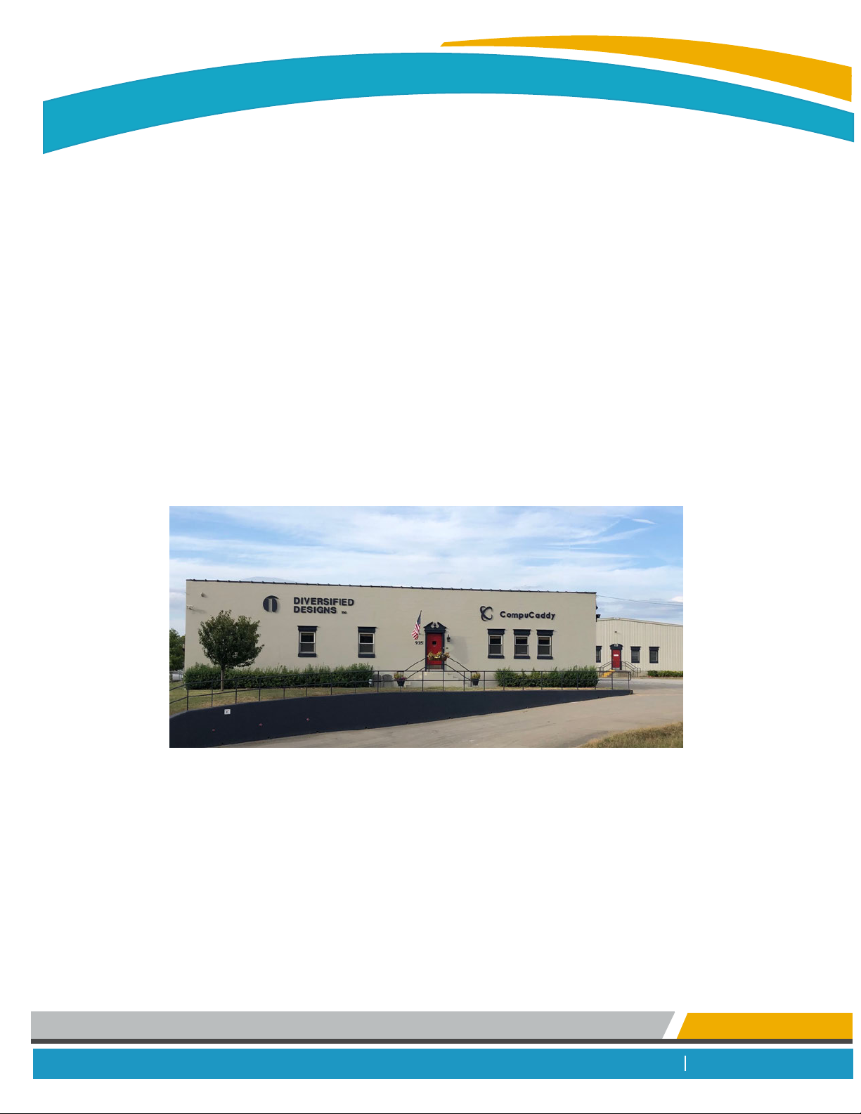
Very Proudly Made In the USA!
CompuCaddy manufacturing facility located in Louisville, KY
Thank you for selecting CompuCaddy for your mobile computer cart needs.
CompuCaddy Contact Information
Address: 935 West Oak Street Louisville, KY 40203
Telephone: (502) 561-0732
Email: sales@compucaddy.com
Tech Support: techsupport@compucaddy.com
Website: www.compucaddy.com

502.561.0732 www.compucaddy.com
MOBILE COMPUTER CARTS, POWER SYSTEMS, AND WALL MOUNTS
DISCLAIMER
While every precaution has been taken to ensure the accuracy of the contents of this guide, CompuCaddy assumes no
responsibility for errors or omissions. Specifications and product functionality may change without notice.
NOTICE OF COPYRIGHT
CompuCaddy Mobile Computer Cart Owner's Manual © 2014Diversified Designs Inc.
All rights reserved.

502.561.0732 www.compucaddy.com
MOBILE COMPUTER CARTS, POWER SYSTEMS, AND WALL MOUNTS
Table of Contents
1.Getting Started
1.1 Safety 4
1.2 Cart Storage 5
1.3 General Information 6
1.4 Unpacking the Cart 7
1.5 Start up Kit Contents 8
2. Initial Cart Setup
2.1 Monitor Arm Setup 9
2.2 Connecting Hardware 10
2.3 Wire Management 13
3. Initial Power System Setup
3.1 Lithium Iron Phosphate Start up 14
3.2 SLA Set up 16
3.3 Battery Software Installation 18
4. Cart and Power System Features
4.1 Cart Features 23
4.2 Add on Drawer 25
4.3 Power Meter Features 26

502.561.0732 www.compucaddy.com
MOBILE COMPUTER CARTS, POWER SYSTEMS, AND WALL MOUNTS
Table of Contents
5. Cart Care & Troubleshooting
5.1 Cart Care 2
5.2 Cart Troubleshooting 31
6. Specifications
6.1 Cart Specification Sheet 3
7. Warranty
7.1 Cart Warranty 35
7.2 Power System Warranty 36

502.561.0732 www.compucaddy.com
MOBILE COMPUTER CARTS, POWER SYSTEMS, AND WALL MOUNTS
Cart Safety
IMPORTANT WARNINGS
!
DO NOT use the mobile cart in or around water or any other liquid.
DO NOT operate the mobile cart outdoors. Mobile cart is for indoor use ONLY.
DO NOT use the mobile cart's power cord if damaged.
DO NOT remove, modify or bend prongs of mobile cart's power cord.
DO NOT modify any component of the mobile cart's power system.
DO NOT use any type of cleaning solvent or cloth to clean the mobile cart's power system.
Failure to do so can result in injury and/or death.
Contact CompuCaddy immediately if a problem arises with the mobile cart.
** (502) 561-0732 or techsupport@compucaddy.com **

502.561.0732 www.compucaddy.com
MOBILE COMPUTER CARTS, POWER SYSTEMS, AND WALL MOUNTS
Cart Storage
POWERED MOBILE CARTS:
If storing the cart for future deployment:
Step 1. Ensure cart is charged to "FULL" status.
Step 2. Power down all computer equipment and peripherals on cart.
Step 3. Ensure cart's power cord is unplugged from AC wall outlet.
Step 4. Remove fuse(s) from fuse holder(s), located on the side of the battery box. After removing fuse(s) ensure all
PowerTrac Battery Meter LED lights are off.
Step 5. Disconnect all power cables from hypertronic connections on cart's center column sleeve.
Step 6. Ensure cart is stored in a safe and dry location.
Note: STORE FUSE(S) IN A SAFE PLACE. Fuse(s) must be inserted back into the fuse holder(s), located on the cart's battery
box, upon restarting the cart.
IMPORTANT: Cart must be charged to "FULL" status at least once every
3 months while cart is being stored. Failure to do so could permanently
damage the battery and void the battery warranty.
!
NONPOWERED MOBILE CARTS:
If storing the cart for future deployment:
Step 1. Power down all computer equipment and peripherals on cart. (if applicable)
Step 1. Ensure cart is stored in a safe and dry location.

CompuCaddy www.compucaddy.com
Phone: (502) 561-0732
Cart
Serial # :
Configured
For :
Input :
Output :
Battery :
Circuit
Protection :
WARNING : To reduce the risk of fire, do not cover or obstruct the ventilation
openings. Overheating may result. Do not dismantle this device; it does not
contain any user-serviceable parts. Attempting to service the unit could result
an electrical shock. For indoor use only. Do not operate unit with damaged
AC power cords, DC output cords, plugs, or accessories. Device must be
properly connected to a grounded three-prong receptacle. Extension cords
should not be used.
®
FUS-AIO-SP450-1234-01
2x AGC 20amp / 32 VAC Fuse
12V 38.4Ah (2x19.2Ah)
12Vdc 20Adc
120Vac 50/60Hz
Rechargeable Lithium Iron Phosphate
502.561.0732 www.compucaddy.com
MOBILE COMPUTER CARTS, POWER SYSTEMS, AND WALL MOUNTS
General Information
Locate Your Cart's Serial No.
My Cart Information
Purchase Date :
Cart Serial No :
Cart Model & Style : Model = Fusion or Cynergy Style = All-In-One or Hybrid or Laptop
Cart Power System Style / Wattage & Battery Type / Ampage (if applicable) :
Cart Serial# Breakdown
Cart Model
FUS = Fusion Series
CYN = Cynergy Series
Example Serial#:FUS - AIO - SP450 - 1234 - 01
Cart Style
Power System Style
Cart Model
Cart Style
AIO = All-In-One Cart
L = Laptop Cart
H = Hybrid Cart
TC/USD = ThinClient/UltraSlim
Desktop Cart
EP = Epic Power
EPP = Epic Power Plus
PS = Powerstream Power
PSP = Powerstream Power Plus
SP = Stealth Power
SPP = Stealth Power Plus
SPL = Stealth Power Limited
NP = No Power
Wattage:
150 = 150watts
450 = 450watts
Power System Style & Wattage
Battery: Battery Type & Ampage
Example Battery: 12V 38.4Ah (2x19.2Ah)
Rechargeable Lithium Iron Phosphate
Power System
Total Battery Ampage
Power System
Battery Type
*If the mobile cart is nonpowered, this area will be left blank.

Unpacking the Cart
502.561.0732 www.compucaddy.com
MOBILE COMPUTER CARTS, POWER SYSTEMS, AND WALL MOUNTS
Step 1. After removing cardboard lid and packaging, slide
the cardboard sleeve up and remove from pallet.
See Figure A
Contents:
IMPORTANT!! Inspect contents immediately for damage.
Contact CompuCaddy @ ( immediately if damage is discovered.
*Keep original packaging for return of damaged goods.*
(1) Mobile Computer Cart Start-up Kit
( 1 Kit per 10 carts)
(1) Monitor Arm
Note: monitor arm is not
included with Laptop Cart.
Step 3. Locate the start-up kit, monitor arm and/or
accessories if applicable.
Step 2. Lift cart up and off pallet.
See Figure B
Note: this step requires 2 people.
Figure A
Figure B
Cardboard
Sleeve
CompuCaddy®

502.561.0732 www.compucaddy.com
MOBILE COMPUTER CARTS, POWER SYSTEMS, AND WALL MOUNTS
Velcro Dots
Wire Management
Clips
- Owner's Manual
- Power System Manual (applicable with powered carts)
- Add-On Drawer: Security Device Instruction Manual (if applicable)
- Accessories Catalog
*Applicable with Laptop Carts
- Apply to bottom of laptop to raise laptop screen to
desired viewing level
*Applicable with Lithium Powered Carts
- MUST be inserted into side of battery box prior to initializing
power system
- See Initial Power System Start Up instructions
USB Drive
(1) per 10 carts
(4) per cart
(4) per cart
(4) per cart
Bumpers
Fuse Cap and Fuse
(2) for 38.4amp
(3) for 57.6amp
- Use to secure keyboard to cart's keyboard tray
- Use to manage keyboard, mouse and computer wiring
Start-up Kit Contents

Step 1. Using the provided Allen Wrench, install
the threaded Bolt into the Monitor Arm via
the hole on the bottom of the monitor arm.
Step 2. Using a 9/16 wrench and the provided
mounting hardware, secure the monitor arm
to the cart via the pre-drilled hole in the
cart's worksurface. See Figure A
502.561.0732 www.compucaddy.com
MOBILE COMPUTER CARTS, POWER SYSTEMS, AND WALL MOUNTS
Initial Cart Setup - Hybrid Series
1. Mount Monitor Arm to Cart
Monitor Arm Installation
2.Attach Monitor to Monitor Arm Vesa Plate
Step 1. Remove the vesa plate from the monitor
arm via the slider knob. See Figure B
Step 2. Using a phillips screwdriver and the provided
(4) screws, secure the monitor to the vesa
mounting plate. See Figure C
1 RWH,I\ RXDUHHTXLSSLQJWKH0 RQLWRU0 RXQWHG6 FDQQHU%UDFNHW
SOHDVHSODFHLWLQSRVLWLRQEHWZ HHQWKH0 RQLWRUDQGWKH9 ( 6 $ 3 ODWH
EHIRUHLQVHUWLQJDQGVHFXULQJWKHVFUHZ V
Step 3. Secure the mounted monitor to the monitor
arm via the slider knob. See Figure D
Slider Knob
secure vesa plate
to monitor
with (4) screws
turn slider knob clockwise
to secure vesa plate with
monitor to monitor arm
turn slider knob counter
clockwise to release vesa
plate from monitor arm
Vesa Plate (black)
Figure A
Figure B
Figure C
Figure D
monitor arm
pre-drilled hole
in cart worksurface
(1) bolt
(1) large washer
(1) locking washer
(1) locking nylon nut

502.561.0732 www.compucaddy.com
MOBILE COMPUTER CARTS, POWER SYSTEMS, AND WALL MOUNTS
Initial Cart Setup - Hybrid Series continued
Step 1. Place thin client/laptop computer inside
the cart's locking computer compartment.
See Figure A
Step 2. Keyboard: Using the provided velcro dots,
secure the bottom of the keyboard to cart's
keyboard tray. Feed keyboard cord through
opening in back of the cart and up thru
opening in computer compartment, plug
into computer. See Figure B
Step 3. Mouse: Place mouse in mouse house. Feed
mouse cord through opening in back of the
cart and up thru opening in computer
compartment, plug into computer.
See Figure B
Step 4. Using provided wire management clips,
secure excess keyboard and mouse cords
inside cart top. This will prevent obstruction
to the retractable keyboard tray. See Figure C
3. Connect Keyboard and Mouse to the Computer
Connect Hardware & Peripherals
Figure A
Figure B
Figure C
**shown with a thin client computer
feed cord thru opening
in back of cart
feed cord up thru opening
in compartment
secure keyboard to
cart's keyboard tray
place mouse in
mouse house
&
then

502.561.0732 www.compucaddy.com
MOBILE COMPUTER CARTS, POWER SYSTEMS, AND WALL MOUNTS
Initial Cart Setup - Hybrid Series continued
Step 1. Using the Serial/DVI cable, connect the
monitor to the computer hardware.
See Figure A
4. Connect Monitor to the Computer
Connect Hardware & Peripherals
Step 1. Connect the DC Power Cable to the monitor.
See Figure C
Step 2. Confirm the DC Power Cable is installed into the
correct slot on the Dc Power "Snap" Box for
the device being installed.
(located behind the keyboard tray)
See Figure C
6. DC Powered Monitor - Connect the Monitor to the DC Power "Snap" Box
Step 1. Connect the monitor's AC Power Cord to
the Monitor. See Figure B
Step 2. Connect the monitor's AC Power Cord to the
AC Module located inside the
cart's hardware compartment. See Figure B
5. AC Powered Monitor - Connect the Monitor to the AC Module
or
Figure A
Figure B
monitor connection
Figure C
monitor connection
AC output connection
located inside cart compartment
AC Power Cord
AC
Module
DC output connection ("Snap" Box)
located behind keyboard tray wire panel.
DC
Power Cable
DC
Power "Snap" Box

502.561.0732 www.compucaddy.com
MOBILE COMPUTER CARTS, POWER SYSTEMS, AND WALL MOUNTS
Initial Cart Setup - Hybrid Series continued
Step 1. Connect the DC adapter to the computer.
See Figure A
Step 2. Connect the DC adapter to the DC output
connection (hypertronic) located on the
cart sleeve. See Figure A
7. Connect Computer Hardware to the Cart
Connect Hardware & Peripherals
7a. Computer Hardware with the DC Power "Snap" Box
Step 1. Connect the computer's AC power cord
to the computer and the other end to
the AC Module. See Figure B
7b. Computer Hardware with the AC Module
or
Figure A
Figure B
computer connection
computer connection DC output connection ("Snap" Box)
located behind keyboard tray wire panel.
DC
Power Cable
DC
Power "Snap" Box
AC output connection
located inside cart compartment
AC Power Cord
AC
Module

www.compucaddy.com
MOBILE COMPUTER CARTS, POWER SYSTEMS, AND WALL MOUNTS
Initial Cart Setup - Hybrid Series continued
Wire Management
8. Secure Excess Cords to Monitor Arm
**Before securing cables, ensure there is enough cable
slack to accommodate full range of peripheral and
monitor arm motion.
Step 1. Use the provided (2) monitor arm wire
management clips to neatly manage excess wires.
Insert end "A" of clip, into hole of paralink
locking bar (silver) located on the back
of the monitor arm. See Figure A
Step 2. Wrap end "B" of the (2) monitor arm wire
management clip around loose cables and
fasten into end "A". Cables are now secured
to the monitor arm. See Figure B
Figure A
Figure B
End "A"
End "B"
Monitor Arm Wire
Management Clips
Paralink Locking
Bar (silver)
Clips

&+ $ 5 * ( 6 7A78 6
6 <6 7( 0 6 7A78 6
LOW BATTERY
AUTO SHUTDOWN
RECOVERY
AC / TIME TO CHARGE
DC / TIME REMAINING
CHARGING
F
1/2
(
3/4
1/4
02:00
CompuCaddy
R
Step 1. Locate fuse(s) and fuse cap(s) in Start-up Kit.
Insert fuse(s) into fuse holder(s), located on
the side of the cart's battery box. 6HH) LJXUH&
Note: LiFePO4 38.4 amp power system will have (2) fuses/caps
LiFePO4 57.6 amp power system will have (3) fuses/caps
Step 2. Using the cart's power cord, plug cart into AC
wall outlet to activate the power system.
Ensure the PowerTrac Battery Meter, located
on the cart's worksurface, reads "AC/TIME TO CHARGE"
and the "CHARGING" light begins flashing after
the cart has been plugged in for approximately
30 seconds. See Figure D
Step 3. Unplug the cart from the AC wall outlet.
Ensure the PowerTrac Battery Meter, located
on the cart's worksurface, reads "DC/TIME REMAINING".
This will indicate that the power system
is working correctly. See Figure E
Note: if the PowerTrac Battery Meter is not
working as described in Step 2 and/or Step 3
contact CompuCaddy Tech Support @ (502 5610732
if the PowerTrac Battery Meter is working properly,
proceed to Step 4.
502.561.0732 www.compucaddy.com
MOBILE COMPUTER CARTS, POWER SYSTEMS, AND WALL MOUNTS
,QLWLDO3 RZ HU6\ VWHP 6WDUW8 S/ LWKLXP ,URQ3KRVSKDWH6WHDOWK3RZ HU
Figure C
Figure D
insert fuse into fuse holder,
push in & turn clockwise
to lock fuse into place
AC wall outlet &
cart's power cord
PowerTrac Battery Meter
&+ $ 5 * ( 6 7A78 6
6 <6 7( 0 6 7A78 6
LOW BATTERY
AUTO SHUTDOWN
RECOVERY
AC / TIME TO CHARGE
DC / TIME REMAINING
CHARGING
F
1/2
(
3/4
1/4
-- : --
CompuCaddy
R
Figure E
PowerTrac Battery Meter

&+ $ 5 * ( 6 7A78 6
6 <6 7( 0 6 7A78 6
LOW BATTERY
AUTO SHUTDOWN
RECOVERY
AC / TIME TO CHARGE
DC / TIME REMAINING
CHARGING
F
1/2
(
3/4
1/4
00:00
CompuCaddy
R
502.561.0732 www.compucaddy.com
MOBILE COMPUTER CARTS, POWER SYSTEMS, AND WALL MOUNTS
,QLWLDO3 RZ HU6\ VWHP 6 WDUW8 S/ LWKLXP ,URQ3KRVSKDWH6 WHDOWK3RZ HUFRQWLQXHG
For further power system information refer to the CompuCaddy Power System Manual.
Figure F
"F" indicates battery
is fully charged
CompuCaddy
POWER SOURCE
WALL / AC
BATTERY / DC
CHARGE STATUS
CHARGING
LOW BATTERY
SYSTEM STATUS
AUTO SHUTDOWN
RECOVERY
PowerTrac Battery Meter
Step 4. Using the cart's power cord, plug cart into AC
wall outlet until PowerTrac Battery Meter, located
on the cart's worksurface, reads battery "Full" and
the "AC/TIME TO CHARGE" digital clock reads "00:00".
See Figure F
Step 5. If deploying the cart immediately, proceed to
Initial Cart Setup section of this manual.
Step 6. If storing the cart for future deployment, ensure
cart's power cord is unplugged from AC wall outlet
and remove fuse(s) from fuse holder(s), located on
the side of the battery box. See Cart Storage section
of this manual for further information about storing the cart.
Note: STORE FUSE(S) IN A SAFE PLACE.
Fuse(s) must be inserted back into the fuse holder(s),
located on the cart's battery box, upon restarting the cart.
,0 32 5 7$ 1 7Cart must be charged to "Full" status at least
once every 3 months while cart is being stored. Failure to do so
could permanently damage the battery and void the battery warranty.

&+ $ 5 * ( 6 7A78 6
6 <6 7( 0 6 7A78 6
LOW BATTERY
AUTO SHUTDOWN
RECOVERY
AC / TIME TO CHARGE
DC / TIME REMAINING
CHARGING
F
1/2
(
3/4
1/4
-- : --
CompuCaddy
R
&+ $ 5 * ( 6 7A78 6
6 <6 7( 0 6 7A78 6
LOW BATTERY
AUTO SHUTDOWN
RECOVERY
AC / TIME TO CHARGE
DC / TIME REMAINING
CHARGING
F
1/2
(
3/4
1/4
02:00
CompuCaddy
R
Step 1. Ensure (1) fuse is secure in fuse holder, located on
the back left side of the battery box.
See Figure C
Step 2. Using the cart's power cord, plug cart into AC
wall outlet to activate the power system.
Ensure the PowerTrac Battery Meter, located
on the cart's worksurface, reads "AC/TIME TO CHARGE"
and the "CHARGING" light begins flashing after
the cart has been plugged in for approximately
30 seconds. See Figure D
Step 3. Unplug the cart from the AC wall outlet.
Ensure the PowerTrac Battery Meter, located
on the cart's worksurface, reads "DC/TIME REMAINING".
This will indicate that the power system
is working correctly. See Figure E
Note: if the PowerTrac Battery Meter is not
working as described in Step 2 and/or Step 3
contact CompuCaddy Tech Support @ (502 5610732,
if the PowerTrac Battery Meter is working properly,
proceed to Step 4.
502.561.0732 www.compucaddy.com
MOBILE COMPUTER CARTS, POWER SYSTEMS, AND WALL MOUNTS
,QLWLDO3 RZ HU6\ VWHP 6 WDUW8 S6 HDOHG/ HDG$ FLG3 RZ HUVWUHDP ( SLF3RZ HU
Figure C
Figure D
CompuCaddy
POWER SOURCE
WALL / AC
BATTERY / DC
CHARGE STATUS
CHARGING
LOW BATTERY
SYSTEM STATUS
AUTO SHUTDOWN
RECOVERY
AC wall outlet &
cart's power cord
PowerTrac Battery Meter
Figure E
PowerTrac Battery Meter
CompuCaddy
POWER SOURCE
WALL / AC
BATTERY / DC
CHARGE STATUS
CHARGING
LOW BATTERY
SYSTEM STATUS
AUTO SHUTDOWN
RECOVERY

&+ $ 5 * ( 6 7A78 6
6 <6 7( 0 6 7A78 6
LOW BATTERY
AUTO SHUTDOWN
RECOVERY
AC / TIME TO CHARGE
DC / TIME REMAINING
CHARGING
F
1/2
(
3/4
1/4
00:00
CompuCaddy
R
,QLWLDO3 RZ HU6\ VWHP 6 WDUW8 S6 HDOHG/ HDG$ FLG3 RZ HUVWUHDP ( SLF3RZ HUFRQWLQXHG
Step 4. Using the cart's power cord, plug cart into AC
wall outlet until PowerTrac Battery Meter, located
on the cart's worksurface, reads battery "Full" and
the "AC/TIME TO CHARGE" digital clock reads "00:00".
See Figure F
Step 5. If deploying the cart immediately, proceed to
Initial Cart Setup section of this manual.
Step 6. If storing the cart for future deployment, ensure
cart's power cord is unplugged from AC wall outlet
and remove fuse(s) from fuse holder(s), located on
the side of the battery box. See Cart Storage section
of this manual for further information about storing the cart.
Note: STORE FUSE(S) IN A SAFE PLACE.
Fuse(s) must be inserted back into the fuse holder(s),
located on the cart's battery box, upon restarting the cart.
,0 32 5 7$ 1 7Cart must be charged to "Full" status at least
once every 3 months while cart is being stored. Failure to do so
could permanently damage the battery and void the battery warranty.
502.561.0732 www.compucaddy.com
MOBILE COMPUTER CARTS, POWER SYSTEMS, AND WALL MOUNTS
For further power system information refer to the CompuCaddy Power System Manual.
Figure F
"F" indicates battery
is fully charged
PowerTrac Battery Meter

Step 1. Ensure USB cable is connected to host computer.
Insert provided USB drive into host computer.
Locate and open the "PS-RC-300-v6.25" file.
See Figure A
Note: USB drive is included in the cart's Start-Up Kit
Step 2. Double click on "setup.exe." file.
See Figure B
Step 3. Select "Next".
See Figure C
502.561.0732 www.compucaddy.com
MOBILE COMPUTER CARTS, POWER SYSTEMS, AND WALL MOUNTS
Power System Features Quick Glance - Install Battery Monitoring Software
Figure A
For further power system information refer to the CompuCaddy Power System Manual.
The Battery Monitoring Software provides extensive monitoring and diagnostic capabilities including event logging,
maintenance scheduling and email alerts. The Graphic User Interface (GUI) is an onscreen display that gives
end users and IT personnel easy access to vital power system information and a true state of charge.
To utilize the full potential of the cart's power system, CompuCaddy strongly recommends installing the Battery Monitoring
Software upon intial setup of the mobile cart. Please refer to the Power System Manual for detailed information regarding
the Battery Monitoring Software.
Figure B
Figure C
This manual suits for next models
3
Table of contents
Popular Outdoor Cart manuals by other brands

Better Homes and Gardens
Better Homes and Gardens BH47-021-099-27 Assembly instructions

STODDART
STODDART CH.BC.0611 Specification, installation and operation manual

SEVEN
SEVEN CHGCT30I-1E user manual

Gorilla Carts
Gorilla Carts GORMP-9 owner's manual

Tektronix
Tektronix K420 instructions

Tripp Lite
Tripp Lite DMCS60100XXCK owner's manual