Compur Monitors Statox 503 User manual

Manual
Statox 503
Control Module
Compur Monitors GmbH & Co. KG
Weissenseestrasse 101
D-81539 Münc en
P one: +49 (0) 89 62038 268
Fax: +49 (0) 89 62038 184
www.compur.com

Statox 503 Control Module
Page 2 of 46 Issue 10 / 2018
Content
Warning Signs ....................................................................................................................................... 4
Mounting .............................................................................................................................................. 6
Dismounting .......................................................................................................................................... 7
Connecting to power supply ................................................................................................................. 8
Start-up ................................................................................................................................................. 8
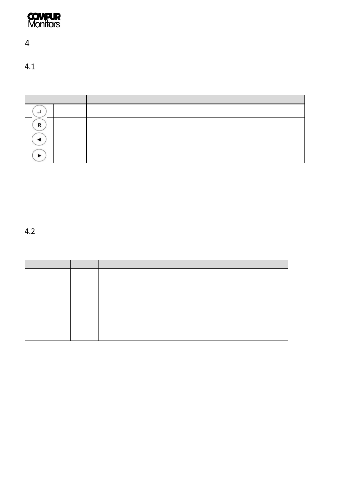
Controls ............................................................................................................................................... 10
LEDs ..................................................................................................................................................... 10
Display ................................................................................................................................................. 11
Communication bus ............................................................................................................................ 12
Electrical connections ......................................................................................................................... 12
Connecting t e external reset and analog output ................................................................... 14
Self Test Trigger for Statox 560 ................................................................................................ 14
Connecting t e internal relays ................................................................................................. 15
Password ............................................................................................................................................. 16
Main menu structure .......................................................................................................................... 17
Service Mode ...................................................................................................................................... 18
Selecting t e measuring program ....................................................................................................... 18
Calibration ........................................................................................................................................... 20
Reading t e bridge voltage ................................................................................................................. 22
Switc ing t e sensor power supply off............................................................................................... 23
Programming t e alarm relays ........................................................................................................... 24
Alarm relays configuration ................................................................................................................. 27
Functional test .................................................................................................................................... 28
Current output in Service Mode ......................................................................................................... 30
C anging t e operation mode – Control Module or Common Alarm Module .................................. 31
Status messages .................................................................................................................................. 34
Error messages.................................................................................................................................... 36
Control Module - Status diagram ....................................................................................................... 38
Common Alarm Module - Status diagram .......................................................................................... 38
Safety Functions .................................................................................................................................. 39
Diagnostic Time and Measuring Cycle ................................................................................................ 40
Installation and Parameter Settings ................................................................................................... 41
Sc edule Maintenance (Prooftest) ..................................................................................................... 41
Repair and Spare Parts ........................................................................................................................ 41
Failure Rates and Safe Failure Fraction .............................................................................................. 41
Average Probability of Failure on Demand ......................................................................................... 42
Classification of t e Safety Integrity Level (SIL) .................................................................................. 42

Statox 503 Control Module
Issue 10 / 2018 Page 3 of 46
Livetime ........................................................................................................................................ 42
Operating t e Statox 503 wit Statox 501 ARE or HRC Sensor .................................................... 43

Statox 503 Control Module
Page 4 of 46 Issue 10 / 2018
Safety notes
Read and observe t is manual prior to installation and start-up.
T e Statox 503 Control Module is only allowed to operate under t e given ambient conditions (see
Tec nical Data). In particular, it must not be operated in potentially explosive atmosp eres!
T e Statox 503 Control Module must be operated, maintained and repaired by trained and expert
personnel only. Use only Compur Monitors original parts for repair and maintenance.
Do not connect t e module directly to mains!
Do not modify t e product. Do not use if damaged or incomplete.
W en installing t is product observe all local standards and regulations.
Disregarding of t e above points represents a danger to people and property.
Warning Signs
Potential Danger
Note on an immediate danger to people and property.
Advice
Extra information for t e proper use of t e product.
!
!

Statox 503 Control Module
Issue 10 / 2018 Page 5 of 46
Product description
T e Statox 503 Control Module can be used in two different modes:
As a Control Module it supplies t e sensor eads for toxic or combustible gases wit energy and andles
t eir signal. It can be configured for different gases and measuring ranges. T e Statox 503 Control Module
displays t e concentration and converts it into a 4 – 20 mA signal at t e analog output. If one of t e
programmed alarm t res olds is exceeded, t e relevant LED goes on, t e relevant relay switc es and t e
relays status is communicated on t e communication bus. T e alarms can be set latc ing or non - latc ing.
Latc ing alarms can be reset by pus ing t e reset button or by an external contact.
Please note:
Sensor eads for toxic gases and oxygen (Statox 501/S, Statox 505 and Statox 506) are protected in
concept Ex i (intrinsic safety) and must be connected via an intrinsically safe repeater, as far as t ey
are intended to be installed in a azardous area (Zone 1 or 2).
Sensor eads for combustible gases and CO
2
(Statox 501 HRC, ARE, LCIR, MCIR and CO
2
) as well as
Statox 501 Infratox and Statox 560 are protected in concept Ex e (en anced safety) or Ex d
(flameproof). T ey can be connected directly to t e Control Module even if t ey are intended to
operate in Zone 1 or 2.
T e Statox 503 can also be operated as Common Alarm Module. It collects t e alarm signals (A1/A2/SF) of
up to 25 connected control modules and generates a common alarm on LEDs, relays and its analog output.
T is way you can set up a multi - c annel gas detection system. Prerequisite is t at all modules are connected
to eac ot er via bus adapter. An error from t e Control Module or t e connected sensor eads will appear
on t e respective Control Module as well as on t e Common Alarm Module.
If power supply is provided via t e optional bus plugs, it is possible to replace t e modules during operation
wit out effort.

Statox 503 Control Module
Page 6 of 46 Issue 10 / 2018
Getting started
T e Statox 503 control modules are designed for mounting on DIN rail TS 35. Due to t e tilted
mounting/dismounting of t e modules t e span between t e outsides of t e rail and t e wall below and
above t e Statox 503 Module must be at least 80 mm (3.15 “). Furt ermore at least 120 mm (4.72 “) must
be remain free between two rail lines.
Mounting
T e Control Module can be operated wit out bus adapter, t ey will be mounted on t e
DIN rail as s own in Figure 2. In t is case eac module must be powered separately wit
24 VDC.
1. Plug t e bus adapters toget er and snap t em on t e DIN rail as s own in Figure 1.
2. Incline t e module and move it to t e lower part of t e DIN Rail. See Figure 2.
3. Now pus t e module forward to t e rail against t e resistance of t e spring lock, until you ear
it snapping in.
Set wit 2 bus adapters, obligatory
for eac module in bus operation,
Art.# 557002
Connection set for bus adapter
(Bus plug left and rig t),
optional, Art.# 557003
DIN rail TS 35
Figure
1
: Requirements for bus operation sample installation
Control Module, Art.# 555500
Control Module, Art.# 555500, configured as Common Alarm Module
Power supply
24 VDC
!

Statox 503 Control Module
Issue 10 / 2018 Page 7 of 46
You can combine modules of t e Statox 503 series in any sequence. Adding or removing one module as no
impact on t e ot ers. You can save wiring effort starting wit t e power supply on t e outside and connecting
it to t e bus wit t e bus plug. Alternatively t e first module in a row can be connected to 24 ± 2 VDC, t e
ot ers will be supplied via bus. T e power rail is rated for 30 modules max. in one row. You can interconnect
multiple rows wit t e optional bus plugs (Connection set Art.# 557003, 1 set per rail is needed). For furt er
information see Accessories list chapter 12.
A combination of Statox 502 and Statox 503 Control Modules on one DIN Rail is possible.
Please observe t e different assignment of terminal 11.
Dismounting
Pull t e spring lock wit a screw driver and incline t e module simultaneously, see Figure 3. T is can be done
under operating conditions.
1
2
Figure
3
:
Dismounting from DIN rail
Figure
2
:
Mounting to DIN rail
!

Statox 503 Control Module
Page 8 of 46 Issue 10 / 2018
Connecting to power supply
Do not connect t e module directly to mains! Do not s ort circuit terminals! Bot can
destroy t e module!
T ere are two options connecting t e 24 VDC power supply, see Figure 4.
a) Via bus plug to t e communication bus
b) Directly to t e relevant Statox 503 Control Module terminal
In bot cases all subsequent modules are automatically connected to t e power supply via bus. T e terminals
are rated to take a max. diameter of 2,5 mm
2
. T e module starts operating as soon as it is connected to
power.
Start-up
In any case make sure to select t e appropriate program prior to connecting t e sensor
ead. Ot erwise t e sensor can be damaged.
Ex works t e Statox 503 is configurated to operate as Control Module. After connection to power, it performs
a self-test. It displays t e firmware version, t en for 5 seconds t e actual measuring program, t en “PLEASE
WAIT”. T e module remains in t e system fail mode until t e measuring mode as successfully been
activated. During t is process t e red LED “S” is on.
If no sensor ead is connected, an error message is generated (ERROR 2 or ERROR 5, depending on measuring
program). In t is case activate t e appropriate program as described in chapter 6.1. T en connect t e sensor
ead as described in chapter 9.
!
13
14
1
5
16
+24 VDC
0 V
17
18
19
20
a)
Bus plug (left)
b) Terminal block
5
4
3
2
1
0 V
+24 VDC
Figure
4
: Connecting the power supply
!

Statox 503 Control Module
Issue 10 / 2018 Page 9 of 46
If a sensor ead as been connected and t e appropriate program as been selected, t e measuring mode
will start.
Sensor eads for combustible gases, type HRC, ARE, LC IR, MCIR, CO
2
and PID must be
calibrated after being connected.
Exception: A line calibration as been done by Compur.
T e message „CALIB. REQUIRED“ alternating wit t e measured value, tells you t at t e
combination sensor ead / control module as not been calibrated toget er. T e control
module operates wit default sensor parameters. By pus ing ENTER, t e message „CALIB.
REQUIRED“ can be blanketed. By pus ing ENTER in t e measuring mode, t is message can
be recalled: if t ere was no initial calibration, “NO VALID CAL. DATA“ is s own for 5s.
!
Power ON
Actual firmware version is displayed 20 s
Actual operation program is displayed 5 s.
During t is time an access to t e main menu is possible.
Figure
5
:
Start
-
up
sequence
Measuring Mode

Statox 503 Control Module
Page 10 of 46 Issue 10 / 2018
Product c aracteristics
Controls
T e Statox 503 as four pus buttons.
Button Function
Enter Enter. C eck calibration status (see c apter 3.4).
Reset Deletes wrong entries, resets t e alarm relays, goes one step back in t e menu.
Left
*)
Navigates left in t e menu, reduces a programmed figure, c anges t e first
display line w en in t e measuring mode.
Rig t
*)
Navigates rig t in t e menu
,
increases a programmed figure, c anges t e firs
t
display line w en in t e measuring mode.
*)
In some menus a continuous pus activates t e fast mode
LEDs
T e Statox 503 as 4 status LEDs. T e function of t e individual LEDs is subsequently explained.
Description LED Function
ON Green
Power supply
:
„ON“ Power ON
„OFF“ Power voltage off or too low
A1
Yellow
Relays
1: Alarm t res old exceeded
A2
Yellow
Relays
2: Alarm t res old exceeded
S Red
Failure or service request
:
„Flas ing“ Service Mode
„ON“ System Failure
„OFF“ Measuring mode

Statox 503 Control Module
Issue 10 / 2018 Page 11 of 46
Display
In t e measuring mode t e display s ows t e target gas, t e actual measured value and t e unit.
Example 1 (Combustible gas)
E x p l . G
a s
1 0 0
%
L E L
Example 2 (Toxic gas)
S O
2
1 . 3 4
p p m
In case of an over range exposure, t e full scale value is going to flas .
T e ►- or◄-button c ange t e content of t e upper line to display t e serial number of t e module, t e
end of range value and t e actual program . After 20 seconds t e display goes back to t e standard content
– t e target gas.
Target gas
Serial number
Full Scale value Program active
◄
E
x
p
l
.
G
a
s
►◄
S
N
:
0
0
0
0
0
►◄
1
0
0
%
L
E
L
►◄
P
r
o
g
.
x
x
►
2
0
%
L
E
L
2
0
%
L
E
L
2
0
%
L
E
L
2
0
%
L
E
L
Gas
Measured value
Unit in % LEL (Lower Explosion Level)
Measured value
Unit in ppm (parts per million)
Gas

Statox 503 Control Module
Page 12 of 46 Issue 10 / 2018
Communication bus
T e bus interfaces t e 24 V-power supply and t e alarm signals from one module to t e next.
A Common Alarm Module can evaluate t e alarm signals.
Bus ports Description
0 V
Zero
-
0 V
+24 V
Positive
24 ±
2
VDC
A1
Exceeding alarm
t res old
1 se
ts t e signal on terminal A1 to
Low(0V)
A2
Exceeding alarm
t res old 2 set
s t e signal on terminal A2 to
Low(0V)
SF
A system failure sets t e signal on terminal SF to
Low
(0V)
Figure 6: Bus terminals
Electrical connections
T e Statox 503 operates at 24 ± 2 VDC. Hig er voltage or s ort circuits on t e terminals
may destroy t e module.
T e terminals are pluggable. To remove t e terminal blocks, set t e screwdriver directly over t e screws and
press t e block to t e front side.
T e terminals can take cable diameters up to 2.5 mm
2
.
!

Statox 503 Control Module
Issue 10 / 2018 Page 13 of 46
Terminal
Contact
Function
1
Extern
al
Reset
Remote Reset
2
GND (Extern
al
Reset)
3
0
–
2
2
mA
analog output
Analog output
(must be s ort – circuited if not in use)
4
GND (0
-
2
2
mA
output
)
*
5
Bridge supply
-
Sensor
ead
power supply
*
6
Bridge
Sense
-
Negative
s
ense
-
lead
for
5 wire operation
*
7
Bridge supply 19 ± 1 VDC
Sensor
ead
power supply
**
Sensor ead power supply wit
out
repeater
*
8
Bridge
Sense +
Positive Sense
-
lead for 5 wire operation
*
9
Bridge
center
Sensor
Signal
(mV)
**
10
0
–
2
2
mA
Current input
Sensor Head Transmitter
S
ignal (mA)
11
Statox 560 ST Trigger
Remote Trigger for selftest
(R +
)
**
12
GND
0 V Sensor Head (Transmitter)
13
24 V
Power supply
Power supply
+ 24 V DC
14
Relay
SF NC
System
failure
relay
-
break contact
15
Relay
SF NO
System failure
relay
-
make contact
16
Relay
SF C
System failure
relay
-
central contact
17
GND
Power supply negative
18
Relay
A2 NC
Alarm
relay
2
–
break contact
19
Relay
A2 NO
Alarm
relay
2
–
make
contact
20
Relay
A2 C
Alarm
relay
2
–
central contact
**
21
24
± 1
V Voltage output
S
ensor ead
power supply
wit repeater
22
Relay
A1 NC
Alarm
relay
1
–
break contact
23
Relay
A1 NO
Alarm
relay
1
–
make contact
24
Relay
A1 C
Alarm
relay
1
–
central contact
* Sensor eads type
- Statox 501 HRC
- Statox 501 ARE
- Statox 501 LCIR and CO
2
- Statox 501 MCIR
- Statox 501 PID
** Sensor eads type:
- Statox 501/S
- Statox 501 Infratox
- Statox 505
- Statox 506
- Statox 560
Detailed connection
advice in c apter 9 and in
t e manuals of t e
different sensor eads.
Figure
7
: Pluggable terminal blocks with terminal numbers

Statox 503 Control Module
Page 14 of 46 Issue 10 / 2018
Connecting t e external reset and analog output
A GND-signal on terminal 1 initiates a reset just as pus ing t e RESET button.
T e analog output generates a current analog to t e actual measured value wit 4 mA corresponding to
zero and 20 mA to end of scale. A measured value ig er t an end of scale generates 22 mA.
A system failure causes a current of 0 mA, t e service mode causes a current of 2 or 4 mA (selectable).
If the current output is not in use terminals 3 and 4 must be short - circuited in order to avoid an Error
13!
Self Test Trigger for Statox 560
Pus t e buttons R and Enter for 3 sec at t e same time connects terminal 11 to ground. T is will trigger a
self test on a Statox 560 sensor ead. T e display on t e control module s ows now „START SELFTEST“ for a
few seconds.
In order to activate t is function connect lead 5 of t e sensor ead to terminal 11 on t e control module.
1
2
3
4
0
–
22 mA
Figure
8
: Connections
external
reset and analog output
9
10
11
12
Statox 560
lead 5
Figure 9: Statox 560 Self Test Trigger
Connections

Statox 503 Control Module
Issue 10 / 2018 Page 15 of 46
Connecting t e internal relays
Statox 503 as t ree relays, eac equipped wit one make and one break contact. Two relays monitor
alarm t res old exceeding, one system failure.
System failure relay: T e SF-relay coil is always active and drops out in case of a system
failure or voltage drop.
T e alarm relay parameters can be set in t e main menu. T e SF-relay settings cannot be c anged.
Figure 10 s ows t e contacts:
13
14
1
5
16
NC NO C
SF
17
18
1
9
20
NC NO C
A2
21
22
23
24
NC NO C
A1
!
Figure
10
: Relay contacts (
coil
de
-
energized)

Statox 503 Control Module
Page 16 of 46 Issue 10 / 2018
Statox 503 main menu
Password
T e main menu is password protected. No matter if in t e measuring, t e failure or t e start mode: below
procedure gives access to t e main menu.
T e password is: 1994 (not c angeable)
Figure 91: Password menu
1. Pus ◄- and ► -button toget er for 2 s.
2. Enter t e first digit wit ◄ or ►. Use t e Reset button for corrections.
3. Confirm wit Enter.
4. Continue wit t e next 3 digits t e same way.
5. After confirming t e last digit wit Enter you ave access to t e main menu, provided t e correct
password as been entered.
If message „CODE INVALID“ appears, a wrong password as been entered. Try again after two
seconds.
Press
bot
buttons for 2 s to enter
Increase or decrease value
Next digit
Correction
C ange Menu item
MEASURING MODE

Statox 503 Control Module
Issue 10 / 2018 Page 17 of 46
Main menu structure
After pus ing ◄- and ► -button toget er for 2 s and entering t e password, you ave access to t e main
menu. It is structured as a ring wit 9 different submenus in w ic you can set parameters or perform a
calibration. See Figure . Pus ing t e Reset–button always brings you back into t e measuring mode.
Figure 12: Main menu structure
Submenu
Description Chapt.
CHOOSE PROGRAM
1)
Selecting t e appropriate program for t e relevant sensor ead 6.1
CALIB. ROUTINE
1) 2)
Calibration wit gas 6.2
SENSOR TEST
1) 2)
Display of t e bridge signal in % LEL or mV 6.3
SENSOR POWER
1) 2)
Switc es sensor power off or on 6.4
OUTPUT TEST Test of t e LEDs, relays, alarms and t e analog output 8.1
SERVICE OUTPUT Setting of t e analog output in t e service mode 8.2
MODE Altering t e operation mode (Common Alarm Module or Control Module) 8.3
ALARM 1 RELAY Setting Alarm 1 relays parameters 6.5
ALARM 2 RELAY Setting Alarm 2 relays parameters 6.5
1)
no access if t e Statox 503 is operated as Common Alarm Module.
2)
no access if a program for t e operation of a 4 – 20 mA transmitter is active.
„MENU NOT ACTIVE“ will be s own for 2 s if a menu is not accessible in t e actual mode or
program.
!
ME
ASURING MODE

Statox 503 Control Module
Page 18 of 46 Issue 10 / 2018
Service Mode
As soon as t e menu is entered, t e module goes into t e service mode. T e LED „S“ is flas ing. In t e service
mode t e analog output is locked at 2 or 4 mA. T e alarm LEDs and relays are in ibited.
If no button is pus ed wit in 30 seconds, t e module returns to measuring mode. T is time-out it not active
during zero adjustment and calibration in t e menu „CALIB ROUTINE“
w en switc ing t e sensor ead power supply on or off in t e menu „SENSOR POWER“
(display s ows „SENSOR ON“ or „SENSOR OFF“)
during t e program selection in t e menu „CHOOSE PROGRAM“
during t e bridge voltage is displayed in t e menu “SENSOR TEST”. In t is mode t e time - out is 60
minutes to allow enoug time for maintenance work.
Statox 503 in Control Module Operation
T e sensor eads for toxic gases, oxygen or combustible gases measure t e concentration of t e target gas
in t e field. Statox 503 evaluates t e signal and displays t e value. Any alarm t res old exceeding is signaled
by an LED and t e alarm relays is activated. T e alarm is also communicated on t e bus.
Selecting t e measuring program
In t is menu t e appropriate measuring program can be selected. T e program defines t e target gas, t e
measuring range, t e concentration window for span gas and t e ex - works settings of t e relays. See an
overview of all available programs in t e program listing enclosed wit eac module.
In any case t e first step is always to select t e appropriate program. T is must be done
before t e sensor ead is connected, ot erwise t e sensor can be damaged.
If a new program is selected, t e alarm settings and relay configurations according to t e
program listing are valid and t e calibration data for t e sensor eads type HRC, ARE, LCIR,
MCIR, CO
2
and PID will be erased. A new calibration is necessary.
!
!

Statox 503 Control Module
Issue 10 / 2018 Page 19 of 46
Figure 13: Program selection diagram
1. Pus t e - button to enter t e „CHOOSE PROGRAM“ menu.
2. T e active program is s own on t e display.
3. Pus t e - button to start t e program selection
Now t e time-out is deactivated!
4. Select your program wit t e ◄- or ►- button. Pus and old◄ or ► for t e fast mode.
5. Confirm by pus ing t e - button.
6. T e display s ows „Store“ for 2 seconds.
7. T en t e number of t e new program is s own.
8. Confirm by pus ing t e - button to start measuring wit t e new program.
!
Start
-
up
C ange Menu item
Active program
Select new program,
no Time-Out!
Displayed for 2 sec
New program number.
Pus ENTER to start.
MEASURING MODE
no c ange of program

Statox 503 Control Module
Page 20 of 46 Issue 10 / 2018
Calibration
In t is menu you can perform a calibration of sensor eads type Statox 501 HRC, ARE, LCIR, MCIR, CO
2
and
PID detecting combustible gases, carbon dioxide (CO
2
) and volatile organic compounds (VOC). T e test gas
concentration must be wit in t e permitted range, see program list.
CALIB.
ROUTINE
ZERO
ADJUSTM.
000
APPLY
SPAN GAS
GAS IS
ON
R
R
CALIB.
FINISHED
GAS CONC
(val e) ( nit)
FACTOR
x.yy
DONE
R
CALIB.
FAILED
GAS
(val e) ( nit)
R
R
GAS CONC
ERROR
R
ERROR 6
ERROR 7
ERROR 8
APPLY
SPAN GAS
R
Figure 14: Calibration menu diagram
C ange program
Start zeroing
Flas ing during zero procedure
Zero stable
Flas ing, span gas requested
Span gas detected
Plateau found. S ut off span gas
Enter span gas concentration
Enter response factor. Correctable wit
“R”. Confirm wit “ENTER”.
Displayed for 2 s , calibration successful
Actual concentration
Measuring Mode
Table of contents