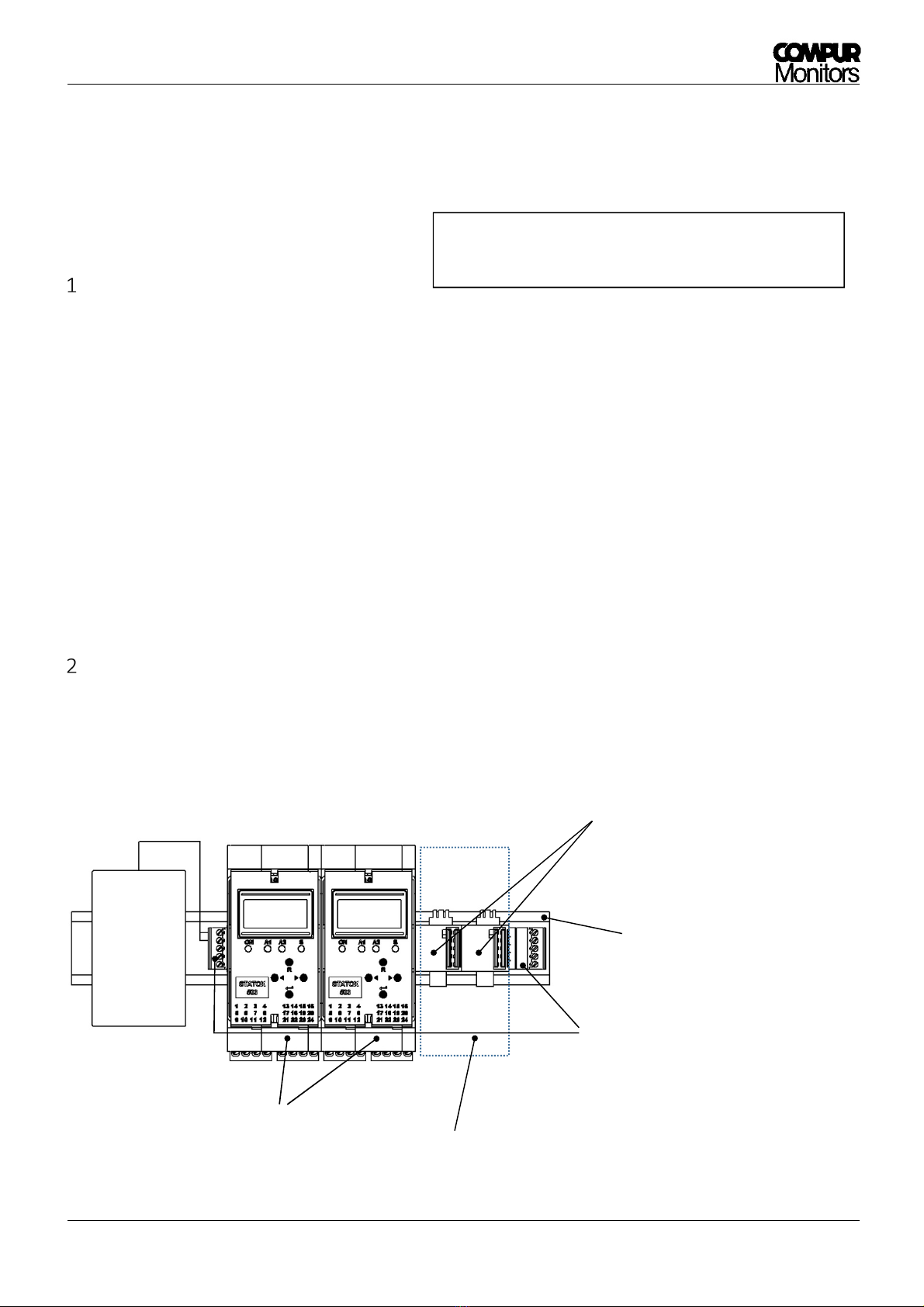
Statox 503 Control Module
Issue 9/2018 Page 9 of 10
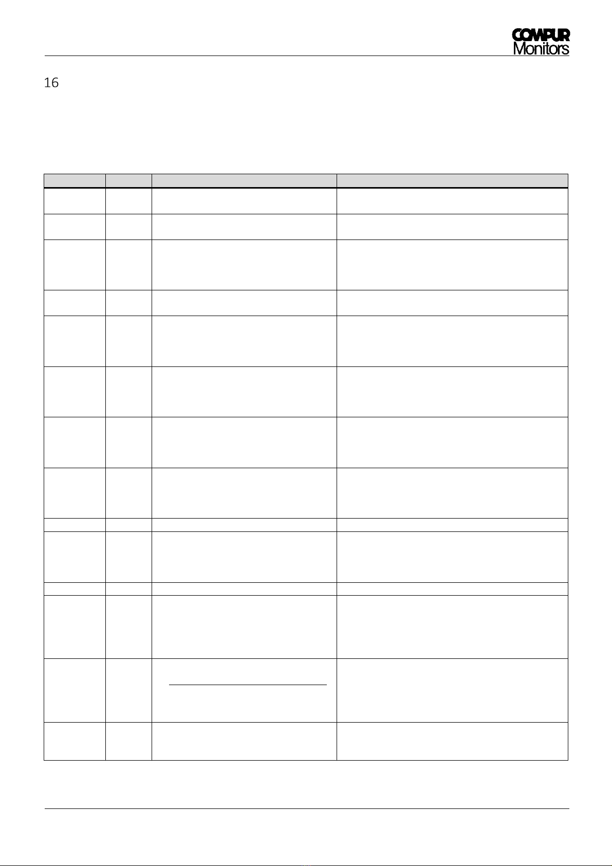
Error messages
In case the d splay stays dark, check the polar ty and the voltage of the power supply. The nternal fuse may be
damaged. In any case cr t cal errors lead to system fa lure.
Display Nature Description Measures
ERROR 1 Cr t cal Short c rcu t n the sensor head cable. Check w r ng and connect ons.
Push R button.
ERROR 2 Cr t cal Cable nterrupt on ( n current mode) or a
connected sensor head transm ts 0 mA.
Check w r ng and connect ons.
Automat c reset after error correct on.
ERROR 3 Cr t cal Cable too long
(only n voltage mode)
Check w r ng and connect ons.
Check selected program.
Connect sensor head and push R button. Eventually
change to 5 w re nstallat on.
ERROR 4 Cr t cal Sensor power supply voltage
cannot be controlled.
Push the R button. If error pers sts contact your
Compur serv ce partner.
ERROR 5 Cr t cal Cable nterrupt on
(only n voltage mode)
Check the sensor head power supply, connect on and
voltage.
Jumper mounted n 3 w re mode?
Connect sensor head and push R button.
ERROR 6 Non
cr t cal Zero not found dur ng t me l m t.
Check connect ons.
If gas s present use zero gas.
Push the Enter button and try aga n.
The old zero value rema ns val d.
ERROR 7 Non
cr t cal Zero sh ft out of spec f cat ons.
Check f gas s present.
Push the Enter button and try aga n.
The old zero value rema ns val d.
Eventually replace the sensor.
ERROR 8 Non
cr t cal
Sensor sens t v ty too low.
No gas or no plateau found dur ng
cal brat on.
Check f gas s on and gas adapter t ghtly connected.
Push ENTER and try aga n.
The old ga n value rema ns val d.
Eventually replace the sensor.
ERROR 9-12 Cr t cal Hardware error Contact your Compur serv ce partner.
ERROR 13 Cr t cal Output current out of spec f cat ons.
Check connect ons.
Term nals 3/4: evaluat on un t or jumper mounted?
Jumper mounted n 3 w re mode?
If error pers sts contact your Compur serv ce partner.
ERROR 14-15
Cr t cal Hardware error Contact your Compur serv ce partner.
GAS
CONC ERROR
Non
Cr t cal
The result of
gas concentrat on x response factor
s out of range.
Check gas concentrat on and response factor entry.
Eventually select another span gas concentrat on.
Push the Enter button and try aga n.
The old ga n value rema ns val d.
Eventually replace the sensor.
CALIB
FAILED
Non
Cr t cal
The result of
gas concentration response factor
s too low.
Check gas concentrat on and response factor entry.
Eventually select h gher span gas concentrat on.
Push the Enter button and try aga n.
The old ga n value rema ns val d.
Eventually replace the sensor.
CALIB
REQUIRED
Non
cr t cal
No val d cal brat on data, measurement
w th default sensor parameters (at start-
up or after change of program).
Blanket w th ENTER. “NO VALID CAL.DATA“ appears
for 5 s. Cal brate w th span gas!