COMSTOCK-CASTLE F3 Series User manual

NOTE: The equipment for which this Installation • Operation Manual is provided may be certified,
have certification pending or not be certified under the standards of one or more of the following
organizations: Intertek Testing Services (ETL) Please refer to the chart on page 3 for the status of each
specific unit.
INSTALLATION • OPERATION MANUAL
for
COMSTOCK-CASTLE FOOD SERVICE EQUIPMENT
FORYOUR SAFETY
Do not store or use gasoline or other flammable vapors or liquids
in the vicinity of this or any other appliance.
WARNING
Improper installation, adjustment, alteration, service, operation or
maintenance can cause property damage, injury or death. Read the
installation, operating and maintenance instructions thoroughly
before installing, operating or servicing this equipment.
NOTICE
Instructions must be posted in a prominent location that will provide
the user of this equipment with procedures, in the event he/she
smells and/or detects gas. This information must be obtained by
consulting the local gas utility.
READ CAREFULLYAND KEEP FOR FUTURE REFERENCE!

COMSTOCK-CASTLE STOVE COMPANY
119 WEST WASHINGTON
QUINCY, ILLINOIS 62301
217-223-5070 (Voice)
217-223-0007 (Fax)
www.castlestove.com
Comstock-Castle Stove Co. suggests that the
user read this Installation/Operation Manual in
its entirety before installing this equipment.
REMEMBER
Follow the instruction manual steps for installation.
Use a qualified gas technician for installation.
Check the unit every time you move for loose fittings
and for being level.
Call the factory if you have any questions about installation or need
the name of a qualified service/installation agent.
CONTENTS: PAGE NO.
Definitions and Shipping Damage..............................................................3
General Information ............................................................................... 3-4
Installation.............................................................................................. 4-5
Gas Connection & Conversion Procedure.................................................5
Lighting Instructions............................................................................... 5-8
Calibration and Adjustments .................................................................. 6-7
Thermostat Calibration........................................................................... 8-9
Manual Pilot and Thermocouple........................................................... 9-13
Preparation...............................................................................................13
Griddle Plate/Broiler Option ............................................................... 13-15
Lava or Radiant Broiler Option.................................................................15
Maintenance and Service Instructions.....................................................15
Drawings............................................................................................ 16-33
Troubleshooting Chart..............................................................................34
Comstock-Castle Warranty .......................................................Back Cover

3
IN THE EVENT YOU SMELL GAS: Turn off gas supply. Open
Windows, Do Not Touch Electrical Switches, Extinguish All Open
Flame, and IMMEDIATELY CALLYour Gas Utility.
DEFINITIONS
QUALIFIED AND/OR AUTHORIZED OPERATING
PERSONNEL
Qualified or authorized operating personnel are those who have
carefully read this manual and are familiar with the functions of
the equipment. Those who have had previous experience with the
functions and operations of similar equipment should also read
this manual to acquaint themselves with the unique characteristics
of this equipment.
QUALIFIED INSTALLATION OR SERVICE PERSONNEL
Qualified Installation and/or Service Personnel are defined as
those who, either in person or through a representative, are
engaged in and are responsible for:
The installation or replacement of gas piping from the outside of
the meter, (or service regulator when a meter is not provided), and
the connection, installation, repair, or servicing of the equipment.
Qualified personnel must be experienced in such work, be
familiar with all precautions required, and be able to comply with
all requirements of state or local authorities having jurisdiction.
Reference: National Fuel Gas Code ANSI Z223.1-latest edition
(NFPA Code 54).
SHIPPING DAMAGE CLAIM PROCEDURE
UNPACKING:
Inspect the crating for posible damage. Carefully remove the
gas appliance from the crate and inspect the unit for concealed
damage. (Preform applicable steps.)
1. Remove top grates and the range griddle plate if applicable.
2. Open oven door, remove rack(s), and oven bottom.
3. All packing material and burner tie down wire, if applicable, must
be removed.
4. If stainless steel, remove the protective covering.
5. Properly install the legs or casters on the range.
NOTE: For proper operation and combustion, the legs or casters
MUST be installed. 10 series, 11 series, & CFHP FHP1-2-3-4.
SUFHP counter units do not have legs.
6. Locate the oven door handle and associated screws. Before
mounting handle, clear the insulation around the mounting
holes on the oven door. Using the two screws, mount handle to
oven door.
Upon receipt and during installation of your new Comstock-Castle
equipment, inspect it thoroughly for damage that may have
incurred during shipment. If damage is evident, contact the carrier
immediately.
FOR YOUR PROTECTION, IF SHIPMENTARRIVES DAMAGED:
NOTE: FILE CLAIM FOR DAMAGES IMMEDIATELY, regardless
of the extent of the damage. Time limits are in effect.
1. VISIBLE LOSS OR DAMAGE - Be certain this is noted on the
freight bill or express receipt and signed by the person making
the delivery.
2. CONCEALED LOSS OR DAMAGE - If damage is unnoticed
until merchandise is unpacked, notify transportation company
or carrier immediately, and file a “concealed damage” claim with
them. This should be done within 15 days of the date delivery is
made to you. Be sure to retain container for inspection.
Comstock-Castle cannot assume responsibility for damage or loss
incurred in transit. Comstock-Castle will, however, be glad to assist
you and furnish you with any necessary documentation to support
your claim.
GENERAL INFORMATION
TOAVOID POSSIBLE INJURY, FIRE, and/or EXPLOSION, the
following precautions must be read, understood, and followed
explicitly.
CERTIFICATION STATUS * MINIMUM CLEARANCE
Combustible Non-combustible
Model Back Side Back Side
OVENS &
RANGES
F3 Series 2” 2” 0” 0”
(ETL)
FK4 Series 6” 6” 0” 0”
(ETL)
P Series 6” 6” 0” 0”
(ETL)
B Series 6” 6” 0” 0”
(ETL)
HOT PLATES
FHP Series 5” 4” 0” 0”
(ETL)
SUFHP Series 6” 6” 2” 2”
(ETL)
KFHP Series 6” 6” 2” 2”
(ETL)
CSP Series 6” 6” 4” 0”
(ETL)
SP Series 6” 6” 4” 0”
(ETL)
GRIDDLES
FHP Series 5” 4” 0” 0”
(ETL)
10 Series 6” 6” 0” 0”
(ETL)
9 Series 6” 6” 0” 0”
BROILERS
FHP Series 5” 4” 0” 0”
(ETL)
9 Series 6” 6” 0” 0”
(ETL)
FRYERS
2932SF 6” 6” 6” 2”
(ETL)
J01HG 6” 6” 6” 2”
(ETL)
2616HG 6” 6” 6” 2”
(ETL)
H Series 6” 6” 6” 2”
All F3 and FK4 Series Ranges of this series are suitable for
installation on combustible floors. Counter equipment is for use on
non-combustible counters.

4
NOTE: The Model No. KFHP Series Hot Plates are not ETL
Certified Designs.
All FHP Series, STFHP Series, and KFHP Series Hot Plates
are for use in combustible and non-combustible locations when
installed on a non-combustible counter.
The BTU input rating on all equipment is calibrated for elevations
up to 2,000 feet above sea level. All orifice drill sizes are
referenced for operation at or below this altitude. For operation
at elevations above 2,000 feet, the BTU rating must be reduced
4% for each 1,000 feet of elevation or the orifice drill size must be
changed appropriately. For high altitude drill sizes, call your local
gas company or Factory Authorized Service Center.
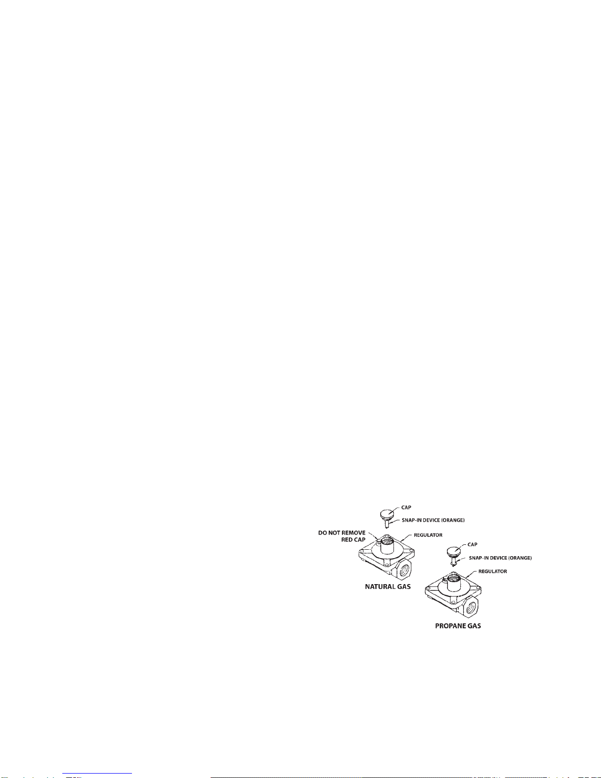
All units are equipped with fixed orifices and cannot be adjusted.
If converting the gas appliance from natural to propane, or vice
versa, all orifices and the regulator must be changed. The correct
type of gas, for which the unit is configured, is noted on the
name plate. The type of gas specified MUST be used. For proper
conversion, contact a qualified service technician or your Factory
Authorized Service Center.
When installed with casters, adequate means of restraint must
be provided to limit the movement of the appliance without
depending on the connector and the quick disconnect device or its
associated piping to limit the units movement. The restraint should
be securely fastened to the back of the unit. If disconnection of
the restraint is necessary, the restraint must be reconnected after
the appliance has been returned to its original installation position.
For a gas appliance that is equipped with casters, the installation
shall be made with a connector that complies with the Standard
for Connectors for Moveable Gas Appliances, ANSI Z21.69 -1987,
and addenda Z21.69a -1989, and a quick disconnect device
the complies with the Standards for Quick Disconnect Devices
for Use With Gas Fuel, Z21.69 latest edition and Z21.41 - latest
edition.
Provisions shall be made in the design of the kitchen, to
ensure an adequate fresh air supply for proper ventilation and
combustion.
Do not obstruct the flow of combustion gases or ventilation air.
Never enclose the bottom of the unit with a raised curb and /or
any other construction that would obstruct the air flow into unit.
One of the most important considerations in the installation of this
unit is ventilation. A commerical gas appliance must be installed
so that the products of combustion are efficiently removed.
However, the kitchen ventilation system must not produce a draft
that would interfere with the proper operation of the burners.
The area around this and any other appliance must always
be kept free and clear of combustibles such as: grease, food
particles, fuel, solvents, cleaning fluids, gasoline, mops, rags, and
etc.
During installation, use thread compound sparingly. Always
use a compound that is impervious to chemical reaction with
propane gases. NEVER put any of the compound on the first two
outer threads. This will minimize the possibility of the compound
breaking free and clogging the pilots, burner orifices, and controls.
When a commerical gas appliance is first installed, the gas
pressure must be checked with a manometer by a qualified
service technician. This will ensure that the existing gas facilities
will deliver the BTU’s of gas required on the rating plate.
WARNING - If the appliance in configured for LP Gas, never
connect the equipment directly to the pressure tank. Damage
will result to the appliance if the tank pressure is not properly
regulated. The regulator supplied with your unit is a low pressure
(1/2 PSI max.) appliance regulator. For proper pressure regulation
specifications, consult your local Factory Authorized Service
Agency or an LP Gas Distributor.
INSTALLATION
THIS APPLIANCE IS INTENDED FOR OTHER THAN
HOUSEHOLD USE
All Comstock-Castle commerical gas appliances are manu-
factured by skilled craftsman using the finest quality materials.
PROPER installation by qualified personnel is essential for safe,
efficient, and trouble-free operation of the unit. Any alteration
and/or tampering, without proper knowledge, tools, and test
equipment, is DANGEROUS and will void all warranties.
The installation must conform with local codes, or in the absence
of locel codes, with the National Fuel Gas Code, ANSIZ223.1
- latest edition.
PRESSURE TESTING:
FAILURETO INSTALL PRESSURE REGULATOR WILLVOID
WARRANTY. (Most units have a convertible regulator.)
The appliance and its indivdual shut-off valve must be dis-
connected from the gas supply piping system during any
pressure testing of that system at test pressure in excess of
1/2 psig (3.45 kPa).
The appliance must be isolated from the gas supply piping
system by closing its individual manual shut-off valve during
any pressure testing of the gas supply piping system at test
pressures equal to or less than 1/2 psig (3.45 kPa).
NOTICE
The proper installation of this gas appliance is the total
responsibility of the end user.
It is the responsibility of the purchaser to determine that the
installer is qualified in installation procedures. Conversion,
connecting gas lines, calibrating thermostats, burners, lighters,
setting gas pressure with manometer, and etc., is all part of
normal installation and will not be paid for under warranty. If a
warranty technician is called out and finds the unit improperly
installed, the end user may be subject to billing.
FOR MAINTENANCE, SERVICE, REPAIRS, OR
INSTALLATION - Contact your dealer or the factory, for your
local Factory Authorized Service Agency.
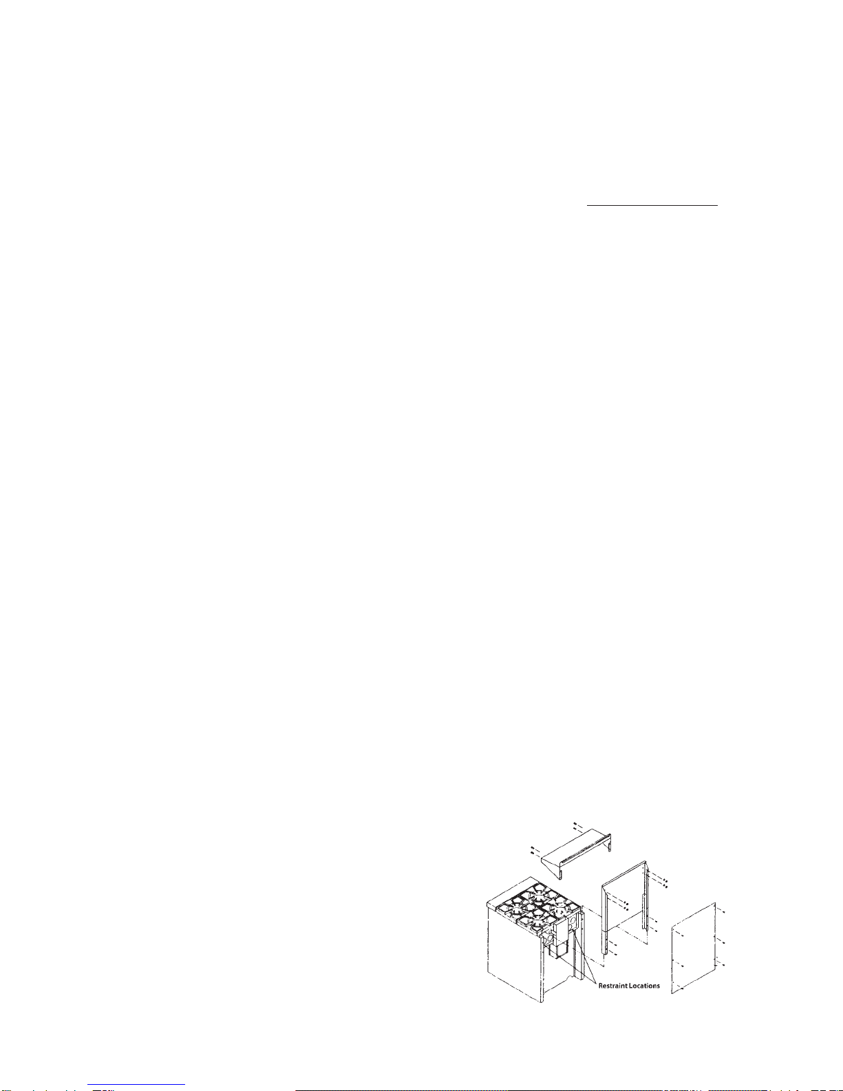
INSTALLING THE BACKSPLASH OR HIGH SHELF:
To install a backsplash or high shelf on a Comstock-Castle Range,
proceed as follows:
1. Ensure back of unit is easily accessible.
2. If mounting low back (backsplash), slide into supports on back
of unit, and secure with #10 x 5/8” sheet metal screws.
3. If mounting high shelf, mount shelf to high back using #24 x
3/4” machine screws with nut and washer.
4. Slide backsplash into the side-supports on back of unit, and
secure with #10 x 5/8” sheet metal screws. (Fig. 1)
Figure 1

4 5
HOOK-UP PROCEDURE FOR COMBINATION UNITS:
Units prefixed with a “2” may be shipped separately. For
connection, set the units side by side. Install backsplash. Install
hook-up strip in the front center of the two units. Ensure that
everything is aligned properly. Install and tighten all screws.
GRIDDLE PLATE INSTALLATION:
Griddle plate front trim must be placed under the plate rest
to prevent plate from moving. Rear of plate must be lifted to
allow front edge under the plate rest. If unit is equipped with
thermostat, sensing bulbs need to be installed under the
plate prior to placing front trim under plate rest.
GAS CONNECTION & CONVERSION
PROCEDURE
GAS CONNECTION:
The size of the gas line is extremely important. If the
line is too small, the gas flow in the manifold will be low.
This inadequate flow will cause slow recovery and delayed
ignition. If in doubt about the proper size of your service line,
consult your local gas utility company.
DO NOT connect appliance before testing the pressure of
the gas service supply piping system.
FOR NATURAL GAS - Fixed orifices are set at 4” W.C.
(water column). If a pressure regulator is supplied, it must be
installed when the unit is connected to the gas supply.
FOR PROPANE GAS - Fixed orifices are set at 10” W.C.
(water column). If a pressure regulator is supplied, it must be
installed when the unit is connected to the gas supply.
Pressure regulator must be tested in a full condition (all
valves “ON”). A condensation/paniculate trap must be pro-
vided in the supply line, with a separate shut-off valve up-
stream of the regulator. These items are customer installation
responsibilites.
Your Comstock-Castle appliance is equipped with a 3/4” NPT
entrance pipe. Level the appliance under station exhaust
hood and connect the gas line from the service gas shut-off
valve to the inlet side of the gas pressure regulator using 3/4”
pipe. DO NOT use a domestic type gas flexible connector. If
a flexible or semi-flexible connector is used, an AGA Certified
Flexible Connector with an inside dimension equal to 3/4” must be
used. Always aviod sharp bends that could restrict the gas flow to
the appliance. All piping must be installed in accordance with local
codes, or in the absence of
local codes, with the National Fuel Gas Codes: ANSI Z223.1
latest edition - NFPA No. 54.
IMMEDIATELY CHECK the plumbing with a concentrated
soap solution or an approved gas dector. Coat all joints
associated with the gas distribution system. Bubbles indicate
leaks and the appliance MUST NOT be operated until the
leak is corrected. NEVER use an open flame to test for
leaks. Be sure to check all gas connections with the main
burner “ON” and “OFF”. Check and, if necessary, adjust the
manifold pressure.
GAS CONVERSION:
A qualified service technician must be used to safely
convert the appliance from natural gas to propane gas,
or vice versa. The regulator, burner orifices, pilot orifices,
and possibly the pilot lighter bar orifice, if applicable, must be
converted. The appliance must be retested for proper align-
ment, calibration, and gas pressure.
Caution: Never attempt conversion when the unit is hot!
For all manually and thermostatically controlled equipment:
If a regulator has been shipped with the unit, it MUST be installed
properly. If not factory installed, connect regulator with arrow
pointing in the direction of gas flow. Use thread compound
sparingly. NOTE: DO NOTAPPLY thread compound to the female
threads of any part.
Some larger models may have two gas inputs for the manifold
system. If this is the case, all gas inputs to the unit MUST have a
factory approved regulator.
IMPORTANT NOTICE FOR UNITSWITH
CONVERTIBLE PRESSURE REGULATORS
PROPANE GAS CONVERSION INSTRUCTIONS
A griddle is equipped with fixed orifice hoods and shipped from
the factory for use on natural gas. To convert to propane gas,
install the propane burner orifice hoods supplied as follows:
1. Remove the griddle plate by lifting with two people and set
aside.
2. Slide the burners back off of the valve orifice hoods a couple of
inches and let it rest.
3. Remove the natural gas orifice hoods with a 1/2” wrench.
4. Apply a very little bit of pipe dope on the threads of the valve.
DO NOTAPPLY PIPE DOPE INTO ORIFICE HOOD.
5. Attach the supplied propane burner orifice hoods with a 1/2”
wrench.
6. Convert the pressure regulator from Natural to Propane gas by
inverting the snap-in device beneath the cap on the regulator.
This will require a fair amount of pressure. Do not remove the
spring. When replacing the cap make sure the snap-in insert
goes down on top of the middle of the spring. (Fig. 2)
7. Test for proper pressure; 10” W.C. (water column) using a
manometer.
8. Slide burners back onto the orifice hoods.
9. Apply the Propane “Notice” stickert to the front of the unit for
futer reference.
Figure 2
LIGHTING INSTRUCTIONS
NOTE: While lighting a manual pilot system, sufficient time
must be allowed for the proper pilot flame to heat the thermo-
couple that will hold the safety valve open. If lighting for the
first time, allow some time for air to be purged from the gas
distribution system.
This manual suits for next models
14
Table of contents
Popular Commercial Food Equipment manuals by other brands

Diamond
Diamond AL1TB/H2-R2 Installation, Operating and Maintenance Instruction

Salva
Salva IVERPAN FC-18 User instructions

Allure
Allure Melanger JR6t Operator's manual

saro
saro FKT 935 operating instructions

Hussmann
Hussmann Rear Roll-in Dairy Installation & operation manual

Cornelius
Cornelius IDC PRO 255 Service manual

Moduline
Moduline HSH E Series Service manual

MINERVA OMEGA
MINERVA OMEGA DERBY 270 operating instructions

Diamond
Diamond OPTIMA 700 Installation, use and maintenance instructions

Diamond
Diamond G9/PLCA4 operating instructions

Cuppone
Cuppone BERNINI BRN 280 Installation

Arneg
Arneg Atlanta Direction for Installation and Use