manuals.online logo
Brands
  1. Home
  2. •
  3. Brands
  4. •
  5. Conbraco Industries
  6. •
  7. Control Unit
  8. •
  9. Conbraco Industries APOLLOPRESS Owner's manual

Conbraco Industries APOLLOPRESS Owner's manual

Conbraco Industries Inc. Pageland S.C. 29728 Telephone (704) 847-9191 Apollovalves.com
I893900 REV. E
APOLLOPRESS
®
BALL VALVE
INSTALLATION, OPERATION, & MAINTENANCE GUIDE
INSTALLATION
APOLLOPRESS
®
ball valves are bi-directional and are a quick, convenient way to connect copper pipe. They are compatible
with all standard press tools and jaws. They may be installed in vertical or horizontal pipe runs without regard to flow direction
and without regard to stem orientation. All APOLLOPRESS
®
ball valves have EPDM seals and are designed for operating
temperatures between 0°F to 250°F
Note: Special considerations must be taken with respect to pipe line expansions and contractions and the media expansions
and contractions within the piping system. Adequate clearance for the press tools must also be considered when planning an
installation.
Preparing the Tube
Cut the desired length of tubing using a tubing cutter squarely. De-burr the inside and outside diameter of the tube with a
rounded file or de-burring tool. Clean the tube of all dirt, oil, grease or foreign matter.
Inserting the Tube
Make sure that the O-ring seals are in place and free of dirt, oil, grease or other foreign matter. Insert the tube into the valve
using a twisting motion. Make sure that the tube is fully inserted until it stops.
Warning: Do no lubricate the seal in the valve with petroleum based
lubricants as this will cause damage to the O-rings.
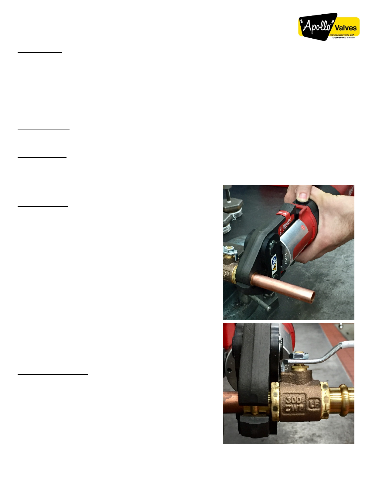
Pressing the Valve
1. Place open jaws around valve connection. Make sure the contour
of the jaw set is properly aligned with the seal bead of the valve
connection
2. Actuate press tool. The pressing cycle takes 4-8 seconds,
depending on the press tool. Once a press cycle begins, and the
rollers contact the jaw arms, the tool will lock-on and automatically
complete the press cycle.
3. Press jaw arms to pen jaw set. If tool malfunctions, please refer to
specific tool operator’s manual.
4. Remove the press tool and jaw connection.
Caution: Jaw set must be square to the tube and properly aligned with the
contour of the valve. Inspect the press tool to verify it is in good working
condition. Inspect the ring/jaw sets and verify that they are clean and do
not display excessive wear. For battery operated units verify that the
battery has an adequate charge. Most quality press tools require re-
calibration after 32,000 cycles. See press tool manufacture’s operating
instructions.
Warning: To avoid pinch point injury, keep hands and fingers away from
jaws. Avoid sharp edges the may have formed on the valves during the
pressing operation.
Inspecting the Connection
1. Check the valve and confirm the presence of the press mark.
2. Inspect the press connection for the following: Misaligned tubes,
tubes not fully inserted, check depth marks, loose connection,
incorrect jaw alignment with the fitting.
3. If one or more of these problems are found, then a new section of
tubing and a new valve will have to be prepared, inserted and
pressed.
4. Test the system for leaks in accordance with normal practice and
local codes.
Conbraco Industries Inc. Pageland S.C. 29728 Telephone (704) 847-9191 Apollovalves.com
Troubleshooting
SYMPTOM POSSIBLE REASONS SOLUTION
Press cycles
produced are
not complete.
Wron jaw set or press rin for the
tube size or material. Install correct jaw set.
The jaw set or rin was not square
to the tube.
Redo the joint with new tube and
valve and make sure that the jaw set
or rin is square to the valve.
Jaw contour was not ali ned with
the valve contour.
Redo the joint with new tube and
valve and make sure that the jaw set
or rin is square to the valve.
The jaw set or rin has exceeded life
expectations and may have failed.
If cracked, replace old jaw set with a
new jaw set and redo the joint usin
a new tube and valve.
Excessively lar e
or sharp fins
present at press
joint partin line
where jaw or
rin tips come
to ether.
Copper material build-up on jaws or
rin s in the contoured profile area
near jaw or rin tips.
Clean jaw sets or rin s in the
contoured area usin metal
polishin pads such as Scotch-Brite®.
Refer to the press tool's
maintenance section for proper
instructions
Excessively worn or dama ed jaw
sets or rin s.
Discard jaws or press rin and
replace with a new jaw set.
Jaws stick to
valve excessively
after completin
joint.
Copper material build-up on jaws or
rin s in the contoured profile area
near jaw or rin tips.
Clean jaw sets or rin s in the
contoured area usin metal
polishin pads such as Scotch-Brite®.
Refer to the press tool's
maintenance section for proper
instructions
OPERATION
The valve handle is marked showing proper rotation direction for “ON” and “OFF” positions. Standard rotation is clockwise for
“OFF” (closed) and counterclockwise for “ON” (open).
MAINTENANCE
Normal stem packing wear can be compensated for by tightening the packing gland nut. The top nut and the lever
may need to be removed for easy access to the packing nut. Tighten the packing nut clockwise in 1/8 turn increments until
observed leakage stops. (Packing wrench part number H371400 is available to ease this operation.) Reinstall the handle
and handle nut after adjustment.
FOR NON-LEAD FREE VALVES: It is illegal to use this product in the United States for potable water services
(water intended for human consumption).
FOR LEAD FREE VALVES: This product complies with U.S. Safe Drinking Water Act (SDWA). Suitable for potable
water applications intended for human consumption.

Other Conbraco Industries Control Unit manuals

Conbraco Industries Apollo 70-600 Series Technical Document

Conbraco Industries

Conbraco Industries Apollo 70-600 Series Technical Document

Popular Control Unit manuals by other brands

GEM B26 operating instructions

GEM

GEM B26 operating instructions

IMI PNEUMATEX Ferro-Cleaner Installation & operation

IMI PNEUMATEX

IMI PNEUMATEX Ferro-Cleaner Installation & operation

SMARTFOX Pro 2 operating instructions

SMARTFOX

SMARTFOX Pro 2 operating instructions

AMX DCE-1 instruction manual

AMX

AMX DCE-1 instruction manual

Weco 4K4LT installation manual

Weco

Weco 4K4LT installation manual

HEROSE 06401 operating instructions

HEROSE

HEROSE 06401 operating instructions

Murata SEM2411D quick start guide

Murata

Murata SEM2411D quick start guide

Nidec Commander C200 Power Installation Guide

Nidec

Nidec Commander C200 Power Installation Guide

Hunter HYDRAWISE X2 quick start guide

Hunter

Hunter HYDRAWISE X2 quick start guide

Gefa DG1 Original instructions

Gefa

Gefa DG1 Original instructions

National Instruments NI 9375 Getting started guide

National Instruments

National Instruments NI 9375 Getting started guide

Canvas 151-7105-0 instruction manual

Canvas

Canvas 151-7105-0 instruction manual

Telnova F6088 user manual

Telnova

Telnova F6088 user manual

Altronix MOM5 installation instructions

Altronix

Altronix MOM5 installation instructions

Lorenz trapeo installation manual

Lorenz

Lorenz trapeo installation manual

OMEX OMEM200 Tuning Manual

OMEX

OMEX OMEM200 Tuning Manual

Rockwell Automation 1734-OE4C installation instructions

Rockwell Automation

Rockwell Automation 1734-OE4C installation instructions

KROHNE Display and adjustment module for OPTISOUND... operating instructions

KROHNE

KROHNE Display and adjustment module for OPTISOUND... operating instructions

manuals.online logo
manuals.online logoBrands
  • About & Mission
  • Contact us
  • Privacy Policy
  • Terms and Conditions

Copyright 2025 Manuals.Online. All Rights Reserved.