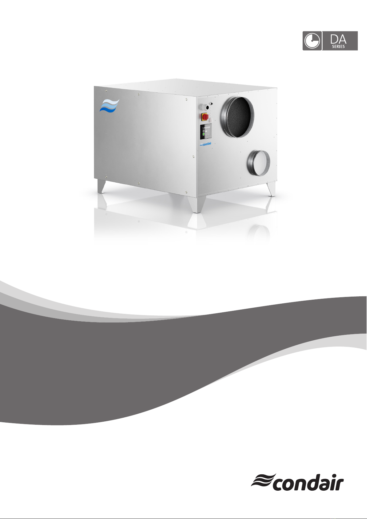
Condair DA 500-4000 Freezer Installation and operating instructions

2606314-0 EN 2306
Dehumidication and Drying
READ AND SAVE THESE INSTRUCTIONS
Desiccant dryer
Condair DA 500-4000 Compact
ADDENDUM MANUAL

Thank you for choosing Condair
Installation date (MM/DD/YYYY):
Commissioning date (MM/DD/YYYY):
Site:
Model:
Serial number:
Proprietary Notice
This document and the information disclosed herein are proprietary data of Condair Group AG. Neither this docu-
ment, nor the information contained herein shall be reproduced, used, or disclosed to others without the written
authorization of Condair Group AG, except to the extent required for installation or maintenance of recipient's
equipment.
Liability Notice
Condair Group AG does not accept any liability due to incorrect installation or operation of the equipment or due
to the use of parts/components/equipment that are not authorized by Condair Group AG.
Copyright Notice
© Condair Group AG, All rights reserved.
Technical modications reserved

3Contents
Contents
1 Introduction 5
1.1 To the very beginning 5
1.2 Notes on the addendum manual 5
2 For your safety 7
3 Important notes 8
4 Product overview 9
4.1 Product designation 9
4.2 Applications 10
4.3 Operation principle 10
4.4 Product description 11
4.4.1 Casing 11
4.4.2 Rotor 11
4.4.3 Air lters 11
4.4.4 Fans for process- and reactivation air 11
4.4.5 Heater for reactivation air 12
4.4.6 Electrical cabinet 12
4.4.7 Operation Options 12
5 Installation 13
6 Commissioning 14
7 Maintenance 15
8 Troubleshooting 16
9 Productspecication 17
9.1 Technical Data 17
9.2 Dimensions DA 500-4000 Compact 18
10 Spare parts 19
11 Built-in components 20
12 EU declaration of conformity 21
13 Appendix 1 – electrical wiring diagram 22

4Introduction
1 Introduction
1.1 To the very beginning
We thank you for having purchased a Condair DA 500 - 4000 Compact desiccant dryer (for short:
Condair DA).
The Condair DA desiccant dryers incorporate the latest technical advances and meets all recognized
safety standards. Nevertheless, improper use of the Condair DA desiccant dryer may result in danger
to the user or third parties and/or damage to property.
To ensure a safe, proper, and economical operation of the Condair DA desiccant dryer, please observe
and comply with all information and safety instructions contained in this addendum manual.
If you have questions after reading this documentation, please contact your Condair representative.
They will be glad to assist you.
1.2 Notes on the addendum manual
Limitation
This addendum manual is a supplement to the Condair DA 500-4000 installation and operation manual
to cover the special properties of the Compact devices.
This installation and operation manual is restricted to the installation, operation and maintenance of
the Condair DA desiccant dryer and is meant for well-trainedpersonnelbeingsufcientlyqualied
for their respective work.

5Introduction
Symbols used in this manual
NOTE!
The catchword “NOTE” used in conjunction with the hand symbol designates important notes in this
manual that require special attention.
CAUTION!
The catchword "CAUTION" used in conjunction with the caution symbol in the circle designates notes
in this operation manual that, if neglected, may cause damage and/or malfunction of the unit or
other material assets.
WARNING!
The catchword "WARNING" used in conjunction with the general caution symbol designates safety
and danger notes in this operation manual that, if neglected, may cause to injury to persons.
DANGER!
The catchword "DANGER" used in conjunction with the general caution symbol designates safety and
danger notes in this operation manual that, if neglected, may lead to severe injury or even death
of persons.
Safekeeping
Please safeguard this addendum manual together with the Condair DA installation and operation manual
in a safe place, where it can be immediately accessed. If the desiccant dryer changes hands, the ad-
dendum manual and the installation and operation manual must be passed on to the new operator.
If the documentation gets misplaced, please contact your Condair representative.
Language versions
This addendum manual is available in other languages. Please contact your Condair representative for
information.

6For your safety
2 For your safety
Note: It is mandatory that you observe and follow all the safety information in section 2 of the installation
and operation manual for the Condair DA 500-4000 desiccant dryer.

7Important notes
3 Important notes
Note: It is mandatory that you observe and follow the information on delivery, transport and storage in
section 3 of the installation and operation manual for the Condair DA 500-4000 desiccant dryer.

8Product overview
4 Product overview
4.1 Product designation
The product designation and the most important unit data of the DA desiccant dryer are found on the
specication label xed below the operation panel (see Fig. 1):
Model DA 500
Serial no. 1927 1901
Manuf. 2022
Voltage 400 V, 50 Hz
Power 4,5 kW
Weight 185 kg
Condair Group AG
Gwattstrasse 17
8808 Pfäfkon
Switzerland
Fig. 1: Specication label

9Product overview
4.2 Applications
The Condair desiccant dryers are based on the sorption principle (see description of the operating
principle in the installation and operation manual for the Condair DA 500-4000 desiccant dryer), which
removes unwanted humidity from the air at normal atmospheric pressure.
The desiccant dryer can be used at air temperatures from 0 °C to 40 °C and humidity values of up to
100 %RH.
Typical elds of application for desiccant drying are:
– Control of humidity in production processes.
– Drying of temperature-sensitive products.
– Maintaining the correct humidity in storage rooms.
– Protection of corrosion-sensitive equipment.
– Humidity control in museums and archives.
– Drying after water damage and drying buildings during construction.
– Climatic improvements in humid rooms.
Compared to the normal design, DA 500-4000 Compact desiccant dryers are characterized by a single-
walled housing without any insulation material. This particular construction offers an excellent solution
for applications where there are not large temperature differences, e.g. with heavily pre-cooled process
air and where noise emissions do not have top priority. In addition, this construction leads to a more
compact device with a signicantly lower weight.
4.3 Operation principle
The operation principle of the DA Compact desiccant dryer is identical to that of the Condair DA 500-4000
standard devices. Please note the information in section 4.3 of the installation and operation manual for
the Condair DA 500-4000 desiccant dryer.

10 Product overview
4.4 Product description
The Condair DA 500-4000 Compact desiccant dryers with applied ducting meet the requirements of IEC
protective class IP23. The electrical panel meets the requirements of IEC protective class IP44.
4.4.1 Casing
The housing is powder coated in RAL7035 and is made from 1 mm thick Aluzinc®. The construction with
sealing material on the panel and internal construction achieves high tightness.
The service-friendly design allows easy access to internal components via a removable front panel. All
air duct connections are prepared for the connection of standard spiral ducts.
4.4.2 Rotor
The desiccant dryer has a drying rotor made of 82% desiccant silica gel, 16% breglass and 2% adhe-
sive sealant. The rotor has a matrix of corrugated and at heat resistant sheets, which houses the Silica
Gel desiccant agent. This matrix creates a large number of axial utes through the rotor, which together
builds up an immense surface area for moisture adsorption in a small volume. The rotor is manufactured
and processed to be able to withstand moisture-saturated air without being damaged. Furthermore, the
rotor will not be damaged even if the fan or the heater for reactivation should fail during operation. The
desiccant rotor is tested according to ASTM E84-18b, and the results are Flame Spread Index (FSI) 0
and Smoke Developed Index (SDI) 0.
Rotor sealings
The rotor has two peripheral seals (PTFE/Silicone) on the rotor casing and four radial seals (PTFE)
Rotor drive system
An electrical gear motor and a belt drive achieve the slow rotation of the rotor. The belt sits on the outer
rim of the rotor and is driven by a pulley on the drive motor. A belt tension device keeps the belt in place
and maintains tension to prevent belt slip. Correct operation of the drive system, and direction of rotation
can be checked by opening the front panel.
The centre hub of the rotor is equipped with ball bearings. The rotor shaft is made from stainless steel.
4.4.3 Airlters
Two separate air lters class ISO coarse ≥65% are installed on the inlet of each air ow. These lters
protect primarily the internal components from dust.
4.4.4 Fans for process- and reactivation air
The device is equipped with two directly driven centrifugal fans, IP54 and ISO F, installed in the device.
The exact type can be found in the respective wiring diagram.

11Product overview
4.4.5 Heater for reactivation air
For the units with electrical reactivation air heating, the reactivation heater is of the PTC-type (Posi-
tive Temperature Coefcient). These special PTC heating elements offer the usual protection against
overheating.
From the DA 1400 onwards, the electrical reactivation heating has a 2-stage control as standard. A
modulated control of the reactivation heater is available as an option.
4.4.6 Electrical cabinet
The electrical cabinet is located in a separate compartment on the service side of the desiccant dryer.
The main switch and PLC display are located on the front on the right-hand side.
4.4.7 Operation Options
The operation of the desiccant dryer with a description of the built-in PLC can be found in the separate
PLC controller manual.

12 Installation
5 Installation
Note: For the installation of the DA desiccant dryer observe and follow the information on installation in
section 5 of the installation and operation manual for the Condair DA 400-5000 desiccant dryer.

13Commissioning
6 Commissioning
Note: For the commissioning of the DA desiccant dryer observe and follow the information on commis-
sioning in section 6 of the installation and operation manual for the Condair DA 400-5000 desiccant dryer.

14 Maintenance
7 Maintenance
Note: For the maintenance of the DA desiccant dryer observe and follow the information on maintenance
in section 7 of the installation and operation manual for the Condair DA 400-5000 desiccant dryer.

15Troubleshooting
8 Troubleshooting
Note: For the troubleshooting, observe the information on troubleshooting in section 8 of the installation
and operation manual for the Condair DA 500-4000 desiccant dryer.

16 Product specication
9 Productspecication
9.1 Technical Data
DA 500 DA 700 DA 1000 DA 1400 DA 2400 DA 3400 DA 4000
Drying capacity at 20°C - 60%rh kg/h 3.3 5.1 7.1 10 13.5 14.5 20
Process air ow nominal m3/h 500 700 1000 1400 2400 3400 4000
Reactivation air ow nominal m3/h 150 220 350 400 500 550 850
Static pressure process air side Pa 300 200 300 200 300 300 200
Static pressure reactivation air side Pa 300 250 200 300 250 200 200
El. power consumption kW 4.5 7.5 11 13.6 19 20.6 28.7
El. power consumption reactivation heater kW 47 10.2 13 17.5 18 26
Admissible temperature °C 0 to 40
Admissible humidity %rF 0 to 100
Power supply V/Ph/Hz 400/3/50
External fuse A 16 16 16 35 50 50 50
Connection diameter process air mm 400
Connection diameter dry air mm 315
Connection diameter reactivation air mm 200
Connection diameter wet air mm 200
Filter class process air 1) ISO Coarse 65%
Filter class reactivation air 1) ISO Coarse 70%
Dimensions (H x W x D) mm 886 x 1145 x 941
Weight kg 120 125 125 130 135 135 140
1) Classication according to ISO 16890

17Product specication
9.2 Dimensions DA 500-4000 Compact
866
1145
941
481.5
233 698.5
284
675
293
ø315
ø200
ø400
ø200
492
344
Process Air In
ø400 mm
Dry Air Out
ø315 mm
Wet Air Out
ø200 mm React. Air In
ø200 mm
Dry Air Out
React. Air In
Wet Air Out
Process Air In
Fig. 2: Dimensions DA 500-4000 Compact

18 Spare parts
10 Spare parts
Note: Information on spare parts for the DA adsorption dryer can be found in section 10 of the installation
and operation manual for the Condair DA 400-5000 desiccant dryer.

19Built-in components
11 Built-in components
Note: Information on built-in components of the DA adsorption dryer can be found in section 11 of the
installation and operation manual for the Condair DA 400-5000 desiccant dryer.

20 EU declaration of conformity
12 EU declaration of conformity
EU declaration of conformity
Condair Group AG
Gwattstrasse 17
8808 Pfäffikon SZ
Switzerland
declare under own responsibility that the product:
Condair Dehumidifier DA 500, DA 700, DA 800, DA 1000, DA 1100, DA 1400, DA 2400,
DA 3400, DA 4000, DA 4400, DA 6000, DA 6400, DA 7400, DA 8000, DA 9400,
DA 13000, DA 19000 and DA 27000 from unit no 128 1512
which is detailed in this declaration complies to the following harmonized European
standards and technical specifications:
EN ISO 12100:2010 Safety of machinery - General principles for design -
Risk assessment and risk reduction (ISO
12100:2010)
EN 60204-1:2018 Safety of machinery - Electrical equipment of machines - Part
1: General requirements
EN 61000-6-3:2007/A1:2011/AC:2012
Electromagnetic compatibility (EMC) - Part 6-3: Generic standards -
Emission standard for residential, commercial and light-industrial
environments
EN 61000-6-2:2005/C1:2005 Electromagnetic compatibility (EMC) - Part 6-2: Generic standards -
Immunity for industrial environments
according to conditions in directive:
2006/42/EC Machinery Directive
2009/125/EC Ecodesign requirements for fans driven by motors with an
electric input power between 125 W and 500 kW
2014/30/EU Electromagnetic Compatibility (EMC) Directive
Pfäffikon 2018-12-12
The manufacturer:
Condair Group AG
Robert Merki
Other manuals for DA 500-4000 Freezer
1
Table of contents
Other Condair Dryer manuals
Popular Dryer manuals by other brands

GE
GE GFDS150EDWW installation instructions

Electrolux
Electrolux T5130 Service manual

Inalto
Inalto IHPD80 user manual

Alliance Laundry Systems
Alliance Laundry Systems 513257R1 Installation & operation

Whirlpool
Whirlpool AWZ 7303 Quick reference guide

Podab
Podab BaseLine TS 4 VP Installation and operation manual