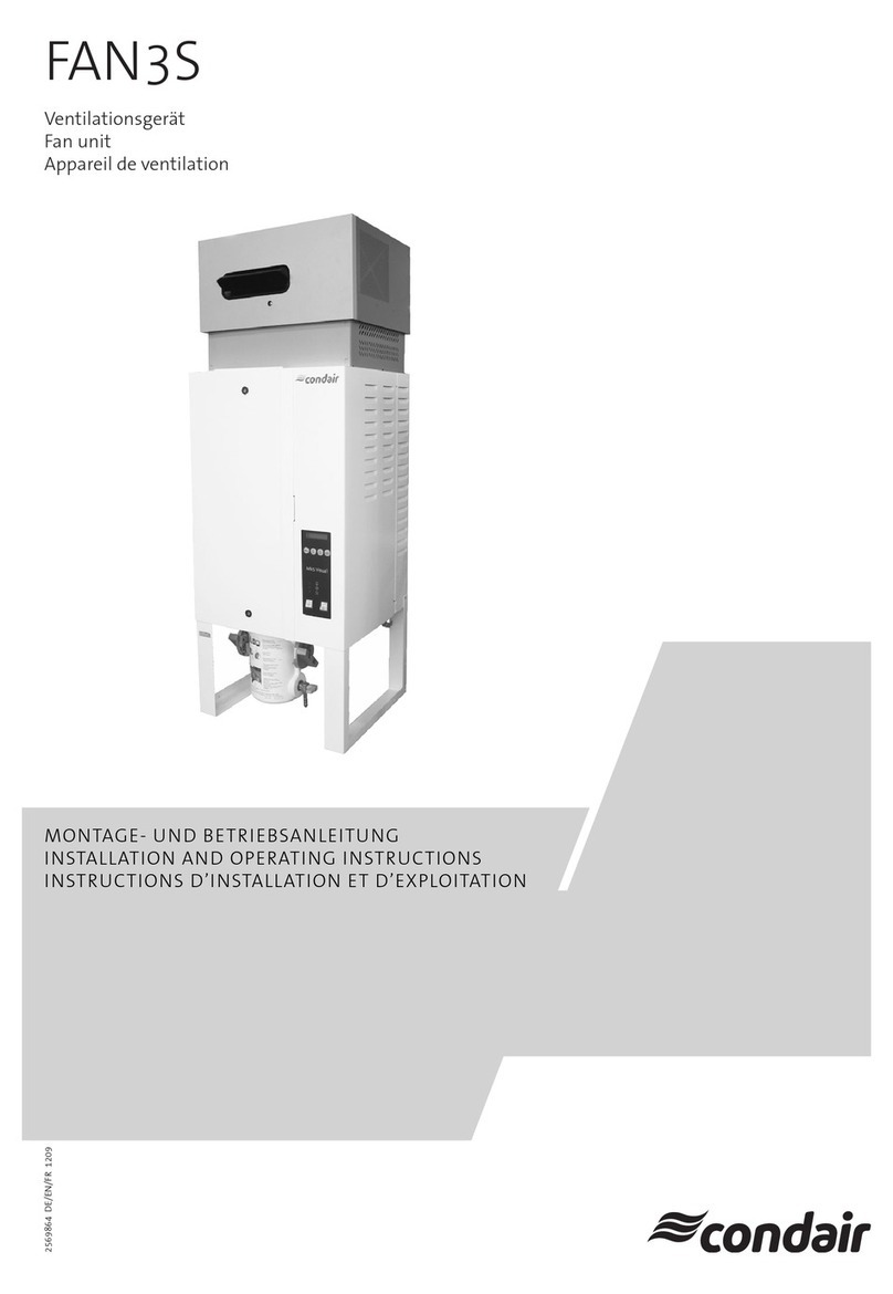
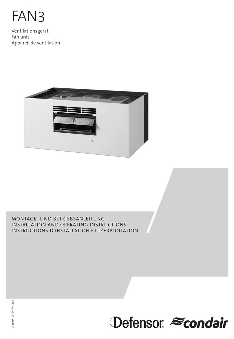
Condair MD Series User manual

2603114-B EN 2112
Humidication and Evaporative Cooling
INSTALLATION MANUAL
Condair HumiLife – the efcient ERV solution
Condair MD

Thank you for choosing Condair
Important!
Please enter the system data listed below during commissioning.
Installation date (DD/MM/YYYY):
Commissioning date (DD/MM/YYYY):
Installation site:
Model:
Serial number:
Supply water hardness at the installation site:
Supply water pH value at the installation site:
Proprietary rights
This document and the information disclosed herein are proprietary data of Condair Group AG. This manual (in-
cluding extracts hereof) may not be reproduced or passed on, nor may the contents thereof be used or passed
on to any third party without the written permission of Condair Group AG. Any infringements are punishable and
entail a liability for damages.
Liability
Condair Group AG is not liable for any damages incurred as a result of poorly executed installation, improper
operation or the use of components or equipment not approved by Condair Group AG.
Copyright notice
© Condair Group AG, All rights reserved
Technical modications reserved

3Table of Contents
Table of Contents
1 Introduction 5
1.1 First things rst! 5
1.2 Notes on installation manual 5
2 For your safety 7
3 Product overview 9
3.1 Model overview 9
3.2 Product labelling 9
3.3 System overview Condair MD 10
3.4 Scope of delivery 11
3.5 Options 11
3.6 Accessories 12
4 Checking delivery/storage and transport 13
4.1 Checking delivery 13
4.2 Storage and transport 13
5 Installation overview 14
5.1 Safety instructions for the installation work 14
5.2 Installation overview Condair MD 15
5.3 Requirements for the installation room 16
5.4 Humidier unit mounting 17
5.4.1 Instructions for positioning the humidier unit 17
5.4.2 Insert the base panel and attach the adapters 20
5.4.3 Attach humidier housing to ceiling or wall 21
5.5 Hydraulic unit mounting 25
5.5.1 Instructions for positioning the hydraulic unit 25
5.5.2 Hydraulic unit mounting 25
5.6 Create hose connections between hydraulic unit and humidier unit 27
5.7 Installation of the fresh water supply and water drain 28
5.7.1 Fresh water supply 28
5.7.1.1 Fresh water supply requirements 28
5.7.1.2 When is a Condair RO-HS reverse osmosis system required? 29
5.7.1.3 Installation of fresh water supply 30
5.7.2 Water drain 31
5.8 Installing the heating water 32
5.9 Humidity control 34
5.10 Positioning and installation of the sensors 36
5.10.1 Positioning sensors 36
5.10.1.1 Installation of the humidity and temperature sensor as well as the max. humidistat 37
5.10.1.2 Mounting the airow monitor 37

4Table of Contents
5.11 Electrical installation 38
5.11.1 Notes on electrical installation 38
5.11.2 Condair MD wiring diagram 39
5.11.3 Connection work for external connections 40
5.11.3.1 Connection of the humidity sensor with humidity control via the integrated humidity controller 40
5.11.3.2 Connection of an external controller 0-10 V 41
5.11.3.3 Connection of the optional maximum humidistat in the supply air or extract air duct 41
5.11.3.4 Connection of the optional airow monitor and the optional oor leak sensor 42
5.11.3.5 Connection of the leak sensor of the humidier unit 42
5.11.3.6 Mains connection (mains socket) 43
5.11.4 Cable entry 43
6 Product specications 44
6.1 Technical data of the hydraulic unit 44
6.2 Technical data of humidier unit 45
7 Appendix 46
7.1 Dimensional drawing of humidier unit 46
7.2 Dimensional drawings of adapters 46
7.3 Dimensional drawing of hydraulic unit 47

5Introduction
1 Introduction
1.1 First things rst!
Thank you for choosing the Condair MD.
The Condair MD has been built using state-of-the-art technology and in accordance with the latest safety
regulations. However, improper use of the Condair MD may put users and/or third parties at risk and/or
may also cause damage to material assets.
Please observe and comply with all information and safety instructions in this documentation and in the
instructions to the components built into the humidier system to ensure safe, proper and cost-efcient
operation of the Condair MD.
Should you have any questions after reading these instructions, please contact your local Condair
partner. We will be happy to assist.
1.2 Notes on installation manual
Delimitations
The subject of this installation manual is the Condair MD. Options and accessories are only de-
scribed insofar as is necessary for proper operation. Please see the relevant instructions for additional
information on the options and accessories.
The information in this installation manual is restricted to the installation of the Condair MD and is
aimed at correspondingly trained specialist staff that has been adequately trained for the cor-
responding activity.
This installation manual is supplemented by various separate documentation (operation manual, spare
parts list, etc.), which are also included in the scope of delivery. Where necessary, this installation manual
may refer to these publications.

6Introduction
Symbols used in this manual
CAUTION!
The signal word "CAUTION" together with the hazard symbol in a circle indicates information provided
in this documentation which, if ignored, could lead to damage and/or the failure of the device or
other equipment.
WARNING!
The signal word "WARNING", together with the general hazard symbol, indicates safety and hazard
information given in this documentation which, if ignored, could lead to injury to people.
DANGER!
The signal word "DANGER", together with the general hazard symbol, indicates safety and hazard
information given in this documentation which, if ignored, could lead to serious injury or even death
to people.
Storage
Please keep this installation manual in a safe place where they can be accessed at all times. If the
product changes owner, the installation manual must be handed over to the new operator.
If this installation manual are lost, please contact your Condair partner.
Language versions
This installation manual are available in various languages. For more information, please contact your
Condair partner.

7For your safety
2 For your safety
General information
Any persons assigned to installing the Condair MD must have read and understood the installation
manual as well as the operation manual of the Condair MD before starting work on the unit.
An understanding of the content of this installation manual and the operation manual is a basic pre-
requisite for protecting personnel from danger, avoiding improper installation and operating the device
safely and properly.
All pictograms, signs and labelling applied to the Condair MD must be observed and kept in a clearly
legible condition.
Personnel qualications
All actions described in this installation manual may be performed by trained and adequately qualied
specialist personnel authorised by the operator only.
Furthermore, for safety and warranty reasons, interventions may only be undertaken by specialist per-
sonnel authorised by Condair.
It is assumed that all persons entrusted to work on the Condair MD are familiar with and abide by the
regulations on occupational health and safety and accident prevention.
Intended use
The Condair MD is exclusively intended for duct air humidication together with Energy Recover
Ventilation (ERV) within the specied operating conditions. Any other use without the written
permission of Condair is deemed to be improper use and can render the Condair MD hazardous. Any
unintended use shall render guarantee claims void.
Intended use also includes the following: observing all information contained in this documentation
(particularly all safety and hazard warnings).
Danger that may arise from the device:
DANGER!
Risk of electrocution!
The hydraulic unit of the Condair MD operates using mains voltage. If the hydraulic unit is open,
users may come into contact with live parts. Touching live parts may cause severe injury or death.
For this reason: Do not connect the Condair MD hydraulic unit to the power supply until all installation
work has been completed, all installations have been checked for correct operation and the hydraulic
unit has been correctly closed and locked again.

8For your safety
Avoidance of hazardous operating conditions
All persons entrusted to work on the Condair MD are obliged to report to the appropriate ofce or person
representing the operator on any changes to the system that affect safety, and secure the Condair MD
against being switched on accidentally.
Unauthorized modications to the device
No additions or modications must be made to the Condair MD without the written permission of Condair.
When replacing any defective components on the unit, use only genuine accessories and spare parts
provided by your Condair partner.

9Product overview
Condair Group AG, Gwattstrasse 17, 8808 Pfäfkon SZ, Switzerland
Type: Condair MD Serial no.: XXXXXXX 11.19
Voltage: 230V/1~/50-60Hz El. output: 800.0 VA 3.4 A
Humidier output: 2 kg/h
Water pressure: 1.5 to 5 bar, <30°C Code: MD-EL-2HE
Engineered in Switzerland, made in Germany
3 Product overview
3.1 Model overview
The Condair MD consists of a hydraulic unit and a humidier unit for installation in horizontal ventila-
tion ducts and has a maximum humidication output of 2 kg/h. The humidication water is heated via
the integrated heat exchanger, which is connected to the heating water system (35 ° C… 60 ° C) of a
connected to a oor/wall-based heating system with a circulation pump or a convection circuit with a
circulation pump.
Note: The stated humidication output is the maximum value, measured at an air throughput rate of
180 m3/h. The effective humidication output depends on the heating source output, the condition of the
supply air and the adjusted humidity setpoint. The output has been veried by Fraunhofer Institute for
Solar Energy Systems (ISE), Freiburg, Germany.
The functionality of the Condair MD can be enhanced using various options. Different accessories and
consumables are also available.
3.2 Product labelling
The type plate features the product labelling:
Type designation Serial number (7 digits)
Production date,
month/year
Connection voltage
Maximum humidication output
Permissible water connection pressure
Electrical output
Field with test marks
Variant code

10 Product overview
3.3 System overview Condair MD
Fig. 1: System overview Condair MD
1Fresh water supply shut-off valve
2Water treatment (optional)
3Fresh water supply connection
4Drain connection
5 Drain funnel with siphon
6Service uid connection
7 Humidier unit supply
8 Humidier unit return
9 Hydraulic unit
10 Mains connection cable
11 Mains socket (230V/1~/50Hz)
12 Mains connection adapter CH
13 Humidier unit
14 Humidity sensor with humidity limitation
15 Air ow monitor
16 Maximum humidistat supply or extract air duct (optional)
17 Energy recovery ventilation (ERV)
18 Heating water supply connection
19 Heating water return connection
20 On-site heating water installation
17
13
16 14
17
12
10
11
16
20
5
3 4
1
2
9
18 19
6
8
7
15
Abluft
Zuluft
Water treatment (optional)
Reverse osmosis system
Condair RO-HS
Supply and return of
existing oor/wall-
based heating or
convection circuit

11Product overview
3.4 Scope of delivery
Condair MD is supplied with:
Material Scope of delivery
Condair MD
Humidier unit
Humidier housing 2 kg/h x
Humidier insert 2 kg/h x
Adapters ventilation duct incl. seals x
Screws and wall plugs for wall installation x
Hydraulic unit
Hydraulic unit 2 kg/h with power cable and ø40/ø32 mm reduction
screw connection for water drain connection x
Control Components
Humidity sensor for duct installation incl. connecting cable x
Connecting cable leakage sensor humidier unit x
Installation set
"Large" installation set (all necessary hoses, insulation hoses, hose
connectors, etc.) for establishing the hydraulic connections between
the hydraulic unit and humidier unit
x
3.5 Options
The following options are available for Condair MD:
Option Description
Air ow monitor Air ow monitor with connection cable for duct
installation for monitoring the air ow in the supply
air duct (see also humidity control in Section 5.9).
Max. humidistat Maximum humidistat with connection cable for duct
installation for monitoring the maximum humidity in
the supply air duct or in the exhaust air duct (see
also humidity control in Section 5.9).
Leakage monitoring room Leakage monitoring for rooms without oor drain
consisting of oor sensor and connection cable.
Filter humidier unit Air lter for installation in the humidier unit.
Condair RO-HS reverse osmosis system External reverse osmosis system for supplying
reverse osmosis water to the Condair MD.

12 Product overview
3.6 Accessories
The following accessories are available for the Condair MD:
Accessories Description
Adapters ventilation duct
Adapters for humidier unit incl. seal. The adapters
are available with different connection diameters:
DN125, DN160 or DN180.
Service kit
Service kit for descaling/disinfection of Condair
MD. The service kit includes: A dosing bottle with
quick coupling, a funnel, a container with descaler
granules and a bottle with 1 l disinfectant.

13Checking delivery/storage and transport
4 Checking delivery/storage and transport
4.1 Checking delivery
Following receipt of the delivery:
– Check the packaging for damage.
Any damage must be immediately reported to the transport company.
– Use the delivery note to check whether all components have been delivered.
Report missing components to your Condair partner within 48 hours. Condair Group AG assumes
no responsibility for missing material beyond this period.
– Remove the components from their packaging and check them for any damage. Notify the transport
company immediately should you nd any damaged parts/components.
WARNING!
For hygiene reasons, the humidier insert packaging may only be opened before the humidier
insert is installed.
– Check, according to the device data on the type plate, whether the supplied components are suitable
for installation at the installation location.
4.2 Storage and transport
Storage
The Condair MD components must be stored in the original packaging in a place secured against drip-
ping water under the following conditions until installation:
– Room temperature: 5 to 40°C
– Room humidity: 10 to 75% RH (non-condensing)
Transport
Where possible, always transport the device and components in the original packaging and use a suit-
able means of transport or suitable lifting device.
WARNING!
The customer is responsible for ensuring that staff are trained on handling heavy goods and are aware
of and adhere to the relevant provisions on occupational safety and accident prevention.
Packaging
If the packaging should be disposed of, follow local environmental protection guidelines. Recycle the
packaging material wherever possible.

14 Installation overview
5 Installation overview
5.1 Safety instructions for the installation work
Personnel qualications
All installation work may be carried out by qualied, trained personnel only. It is the responsibility of the
operator to check the qualications.
General information
All information in this installation manual for installation of the device as well as for water and electrical
installation must be observed and complied with.
All local regulations for the installation of the water and electrical systems must be observed and adhered to.
Safety
For some of the installation work, the cover of the hydraulic unit must be removed. It is therefore es-
sential to note the following:
DANGER!
Risk of electrocution!
The hydraulic unit of the Condair MD operates using mains voltage. If the hydraulic unit is open,
users may come into contact with live parts. Touching live parts may cause severe injury or death.
For this reason: Do not connect the hydraulic unit to the mains until all installation work has been
completed, all installations have been checked for correct operation and the hydraulic unit has been
correctly closed and locked again.
CAUTION!
Electronic components on the inside of the Condair MD hydraulic unit are very sensitive to
electrostatic discharge.
For this reason: To protect the electronic components, measures must be taken against damage
due to electrostatic discharge (ESD protection) when the hydraulic unit is open for installation work.

15Installation overview
5.2 Installation overview Condair MD
Fig. 2: Installation overview Condair MD
Max. humidistat sup-
ply air (optional)
Max. humidistat extract air
(optional)
Air ow monitor
Service uid connection JG ø10 mm
Humidier unit return connection JG ø10 mm
Humidier unit supply connection JG ø10 mm
Drain connection ø40 mm
Drain funnel with
siphon
Supply connection G 3/4" (ET)
Drain pipe ø40 mm (min. slope 15%)
by others
by others
Mains socket
(230V/50Hz,
10 A slow-blow, FI 30 mA)
Minimum distance for service
liquid lling
min. 300 mm
307 mm
288 mm
610 mm
430 mm
min. 200 mm min. 300 mm
Free access: at min. 800 mm
min. 200 mm
min. 350 mm
Extract air
Supply air
Shut-off valve
1.5 to 5.0 bar
8 to 30 °C
Max. hose length 3 m
(hoses with a continuous slope of at
min. 15% routed to the hydraulic unit)
Max. cable length 5 m
Heating or hot water installation (by others)
For details see Section 5.8
Heating water return
Heating water supply
Water treatment (optional)
Condair RO-HS
Reverse Osmosis System
50% scaled
Humidity sensor with
humidity limitation

16 Installation overview
5.3 Requirements for the installation room
The humidier unit and the hydraulic unit have been designed for installation in protected indoor spaces.
Please note the following regarding the requirements for the installation site:
– The humidier unit must be installed together with the hydraulic unit in a utility room that has been
protected against unauthorized access.
– The installation room must have a oor drain connected to the on-site wastewater pipe.
Note: If there is no oor drain, the installation of the optional "leakage monitoring" is recommended.
– The room temperature must be between +7°C and +30°C all year round and the humidity between
15% rH and 50% rH (non-condensing) and the room must be ventilated.
– There must be a sufciently large, free ceiling or wall surface at the installation location for mounting
the humidier unit and a sufciently large, free wall surface for mounting the hydraulic unit.

17Installation overview
5.4 Humidier unit mounting
5.4.1 Instructions for positioning the humidier unit
Note: When positioning the humidier unit in the air duct, the air ow direction need not be taken
into account!
Please observe and follow the instructions for positioning the humidier unit:
– The ceiling/wall on which the humidier unit or the hydraulic unit is mounted must have sufcient
load-bearing capacity and be suitable for fastening (see Fig. 3, Fig. 4 and Fig. 5).
Ceiling mounting with threaded rods
Ventilation pipe
Ventilation pipe
Adapter
DN125 (L= 90 mm)
DN160 (L= 73 mm)
DN180 (L= 63 mm)
Adapter
DN125 (L= 90 mm)
DN160 (L= 73 mm)
DN180 (L= 63 mm)
Installation length: 547 mm (DN200)
Installation length: 727 mm (DN125)/693 mm (DN160)/673 mm (DN180)
563 mm
620 mm
L
170 mm
288 mm
Operating weight, humidier unit: approx. 18 kg
Fig. 3: Dimensions ceiling mounting with threaded rods

18 Installation overview
Alternative ceiling mounting with pipe clamps
Ventilation pipe
Ventilation pipe
Adapter
DN125 (L= 90 mm)
DN160 (L= 73 mm)
DN180 (L= 63 mm)
Adapter
DN125 (L= 90 mm)
DN160 (L= 73 mm)
DN180 (L= 63 mm)
577 mm
620 mm
L
288 mm
Operating weight, humidier unit: approx. 18 kg
Installation length: 547 mm (DN200)
Installation length: 727 mm (DN125)/693 mm (DN160)/673 mm (DN180)
Fig. 4: Dimensions ceiling mounting with pipe clamps
Wall mounting
Ventilation pipe
Ventilation pipe
Adapter
DN125 (L= 90 mm)
DN160 (L= 73 mm)
DN180 (L= 63 mm)
Adapter
DN125 (L= 90 mm)
DN160 (L= 73 mm)
DN180 (L= 63 mm)
620 mm
L
288 mm
Operating weight, humidier unit: approx. 18 kg
Installation length: 547 mm (DN200)
Installation length: 727 mm (DN125)/693 mm (DN160)/673 mm (DN180)
Fig. 5: Dimensions wall mounting

19Installation overview
– The installation site must not be exposed to direct sunlight and must be sufciently far away from
other heat sources.
– The humidier unit must be installed at minimum 0.3 m and at maximum 3.0 m above the hydraulic
unit in the supply air duct of the ERV. The pipe lengths between the humidier unit and the hydraulic
unit must not exceed 3 m. In order to avoid standing water in the pipes, it must be taken into account
that the pipes between the humidier unit and the hydraulic unit must be routed with a constant
slope.
– A lter with at least ISO Coarse 80% class (recommended: ISO ePM1 50%) must be installed in the
supply air of the ERV and regularly serviced to ensure hygienic operation. This lter reliably protects
the humidier insert from contamination by dust particles and thus extends the service life of the
humidier insert.
– Position the humidier unit in such a way that it is easily accessible and has sufcient space for ser-
vicing. Minimum distances according to the installation overviews in Section 5.2 must be observed.
– The humidier unit is installed with the enclosed adapters in the central supply air line upstream of
the distributor and downstream of any silencer.
Ceiling mounting with threaded rods: The humidier unit is fastened to the ceiling with four
threaded rods and nuts (see Fig. 3). The fastening material is not included in the scope of delivery.
Alternative ceiling mounting with pipe clamps: The humidier unit is fastened to the ceiling with
two ø200 mm pipe clamps (see Fig. 4). The fastening material is not included in the scope of delivery.
Wall mounting: The humidier unit is attached to the wall with 4 dowel pins and screws (enclosed)
(see Fig. 5).
The total installation length is:
– When using DN125 adapters: 727 mm
– When using DN160 adapters: 693 mm
– When using DN180 adapters: 673 mm
– Without adapters (DN200): 547 mm
– The ceiling or wall on which the humidier unit is mounted must have sufcient load-bearing capacity
as well as stability and be suitable for fastening. The operating weight of the humidier unit is approx.
18 kg.
– To ensure correct operation of the air ow monitor and the max. humidistat, a straight duct section
with a minimum length of 550 mm must be provided upstream of the humidier unit and a straight
duct section with a minimum length of 300 mm downstream of the humidier unit must be provided
for the integration of the air ow monitor and the max. humidistat.

20 Installation overview
5.4.2 Insert the base panel and attach the adapters
1. Disengage the snap fasteners and remove the humidier housing cover.
2. Clean humidier housing, base panel and adapters.
3. Insert the base panel into the humidier housing.
4. Slide the adapters on both sides onto the connection nozzle as far as they will go.
5. Attach the humidier housing cover and fasten with the snap fasteners.
4
4
1
5
3
ø200 mm
2
Adapter
Adapter
Humidier housing
Base panel
Fig. 6: Insert the base panel and attach the adapters
Other manuals for MD Series
7
This manual suits for next models
1
Table of contents
Other Condair Fan manuals