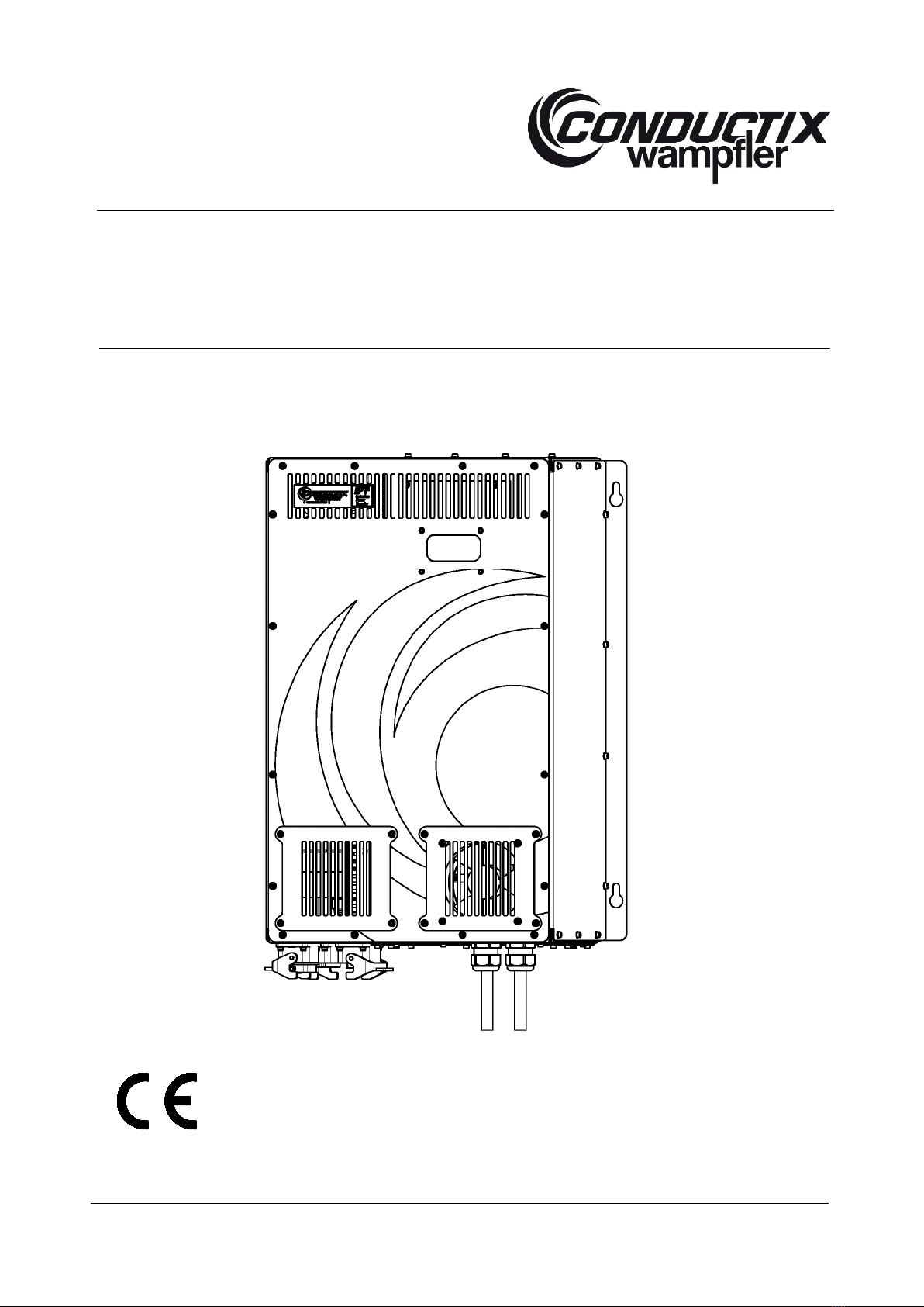
Conductix-Wampfler 91008-111-3090673 User manual

Operation Manual
Track Supply 16 kW Module
80 A/125 A at 400-415 V/440 V/480 V/277 V
BAL9100-0123g-EN
www.conductix.com translated document page 1/56
Part Number
91008
-111-3090673 ( 80 A, 400-415 V, RAL 7016)
91012
-111-3090674 (125 A, 400-415 V, RAL 7016)
91008
-111-3090675 ( 80 A, 480/277 V, RAL 7016)
91012
-111-3090676 (125 A, 480/277 V, RAL 7016)
91000
-111-3090677 (configurable version)

Operation Manual
Track Supply 16 kW Module
80 A/125 A at 400-415 V/440 V/480 V/277 V
BAL9100-0123g-EN
www.conductix.com translated document page 2/56
Index
1General Advice ........................................................................................................................................................................... 5
1.1. Information to these Operating Instructions................................................................................................................. 5
1.2. Limitation of Liability .................................................................................................................................................... 5
1.3. Copyright ..................................................................................................................................................................... 6
1.4. Spare Parts.................................................................................................................................................................. 6
1.5. Warranty...................................................................................................................................................................... 6
1.6. Customer Service ........................................................................................................................................................ 6
2Symbols and Hints ...................................................................................................................................................................... 7
2.1. Requirements Regarding Personnel ........................................................................................................................... 8
2.1.1. Qualification.................................................................................................................................................................. 8
2.1.2. Unauthorized Persons.................................................................................................................................................. 8
2.2. Application in Accordance with the Regulations.......................................................................................................... 9
3Advisory Information for the User ............................................................................................................................................. 10
4Brief Technical Description ....................................................................................................................................................... 11
5Appearance............................................................................................................................................................................... 11
6Technical Data .......................................................................................................................................................................... 12
6.1. Electrical Data | Specifications .................................................................................................................................. 12
6.1.1. Electrical Power Data | Specifications for all Versions............................................................................................... 12
6.1.2. Electrical Input Values | Specifications for Versions with 400-415 V ......................................................................... 12
6.1.3. Electrical Input Data | Specifications for Versions with 440 V.................................................................................... 13
6.1.4. Electrical Input Data | Specifications for Versions with 480 V / 277 V........................................................................ 13
6.2. Physical Data............................................................................................................................................................. 13
6.3. Environmental Data ................................................................................................................................................... 14
6.4. Mechanical Data........................................................................................................................................................ 16
6.5. Interfaces................................................................................................................................................................... 18
6.6. General Features....................................................................................................................................................... 19
6.7. Design Standards...................................................................................................................................................... 19
6.7.1. Design Standards for 400-415 V and 440 V Versions................................................................................................ 19
6.7.2. Additional Design Standards for 480/277 V Versions ................................................................................................ 19
6.8. Protection Features of Track Supply ......................................................................................................................... 19

Operation Manual
Track Supply 16 kW Module
80 A/125 A at 400-415 V/440 V/480 V/277 V
BAL9100-0123g-EN
www.conductix.com translated document page 3/56
6.9. Grounding.................................................................................................................................................................. 20
7Control Board Hardware and Fault Indication........................................................................................................................... 20
7.1. Track Supply Control Board (for specially trained personnel only)............................................................................ 20
7.1.1. Control Board LED Indication..................................................................................................................................... 21
7.2. Track Supply Display Board ...................................................................................................................................... 21
7.2.1. LED Indication............................................................................................................................................................ 22
7.2.2. Software Version Number .......................................................................................................................................... 24
7.2.3. Modes of Operation.................................................................................................................................................... 24
7.2.4. Setting Language, Time and Date.............................................................................................................................. 25
7.2.5. Warning Messages..................................................................................................................................................... 26
7.2.6. Error Codes................................................................................................................................................................ 26
8Fuses ........................................................................................................................................................................................ 29
9Transport, Packaging and Storage ........................................................................................................................................... 30
9.1. Transport ................................................................................................................................................................... 30
9.1.1. Safety Instructions for Transport ................................................................................................................................ 30
9.1.2. Transport Inspection................................................................................................................................................... 30
9.2. Packaging.................................................................................................................................................................. 31
9.3. Storage of Packages ................................................................................................................................................. 31
10 Installation................................................................................................................................................................................. 32
10.1. Who is allowed to do the Installation? ....................................................................................................................... 32
10.2. General Installation Recommendations..................................................................................................................... 32
10.3. Place and Conditions of Installation .......................................................................................................................... 33
10.4. Electrical Regulations ................................................................................................................................................ 33
10.5. Electrical Connection................................................................................................................................................. 34
10.5.1. Mains Connection (X2)............................................................................................................................................... 34
10.5.2. Configuration of Control Plug (X3) ............................................................................................................................. 35
10.5.3. Connection Track Cable (X1)..................................................................................................................................... 36
10.5.4. Layout of the External Connections (X1, X2, X3, X4, X5).......................................................................................... 37
10.5.5. Wiring of the Track Supply ......................................................................................................................................... 38
11 Warnings and Precautions........................................................................................................................................................ 41
12 Commissioning ......................................................................................................................................................................... 42
12.1. Safety ........................................................................................................................................................................ 42
12.2. System Conditions..................................................................................................................................................... 43

Operation Manual
Track Supply 16 kW Module
80 A/125 A at 400-415 V/440 V/480 V/277 V
BAL9100-0123g-EN
www.conductix.com translated document page 4/56
12.3. System Protection ..................................................................................................................................................... 43
13 Start and Operation................................................................................................................................................................... 44
14 Switching-off ............................................................................................................................................................................. 46
15 Emergency Measures ............................................................................................................................................................... 46
16 Fault Diagnosis ......................................................................................................................................................................... 47
17 Maintenance and Servicing....................................................................................................................................................... 48
18 Repair ....................................................................................................................................................................................... 49
19 Disassembly and Disposal........................................................................................................................................................ 50
19.1. Safety ........................................................................................................................................................................ 50
19.2. Reuse ........................................................................................................................................................................ 50
19.3. Disassembly .............................................................................................................................................................. 51
19.4. Disposal..................................................................................................................................................................... 51
20 Spare Parts ............................................................................................................................................................................... 52
21 Tools ......................................................................................................................................................................................... 53
22 Commissioning Report.............................................................................................................................................................. 54
23 Inspection Report...................................................................................................................................................................... 55
This Operating Instruction is based on the following IPT-Technology-Documentation-No.: OM9100-0123f-EN!
Important:
This manual refers solely to the appliance described. See the system description document for information about the complete IPT®
system and the interaction between components.
Company names mentioned in this manual that are registered and protected trade names by copyright remain the property of the
companies themselves.
In order to improve the energy supply system and its function, we reserve the right to carry out technical modifications of illustrations
and statements in this operation manual.
Please find details related to a whole IPT®system in the system manuals. Always refer to the system documentation before starting
any work on the system or components within the system or before operating the system.
Reprint and duplication (even partially) are only allowed with permission from Conductix-Wampfler.
© Conductix-Wampfler GmbH 2016

Operation Manual
Track Supply 16 kW Module
80 A/125 A at 400-415 V/440 V/480 V/277 V
BAL9100-0123g-EN
www.conductix.com translated document page 5/56
1General Advice
1.1. Information to these Operating Instructions
This document describes the component specified on the cover only. The manual does not include details about the interaction of
this component with other IPT®components within a system.
For information relating to the system please read the system and project documentation. Follow these instructions during any work
on the system or operation of the system.
These installation and operating instructions allow the safe and efficient handling of the equipment.
The installation and operating instructions are part of the equipment and must be stored close to the equipment and always
available to the personnel. The personnel must have read carefully and understood these installation and operating instructions
prior to starting work. The basic requirement for safe working is the observance of all safety advice and guidelines specified in
these installation and operating instructions. Moreover you have to observe the local accident prevention guidelines and the
general regulations for the application of the equipment.
Illustrations in this documentation are for basic comprehension and can deviate from the real design of the equipment.
All stated values are based on the metric system. If units of measurement have been omitted, millimetres (mm) apply.
Complementary instructions given in track installation manuals for specific applications, i.e. MV9100-0038 for EMS systems, must
be observed at all times, if of relevance for the installation and operation of the equipment.
1.2. Limitation of Liability
All information and instructions of this operating manual have been compiled with due regard to the standards and regulations in
force, best engineering practice and the findings and experience we have accumulated over many years.
The manufacturer does not accept liability for damage due to:
-Non-observance of the operating instructions
-Improper use
-Use by untrained personnel
-Unauthorized modifications
-Technical modifications
-Use of unauthorized spare parts and accessories
-Improper installation by unqualified installation personnel
The effective volume of delivery may deviate from these explanations and descriptions in case of special design, the utilization of
additional order options or on account of the latest technical modifications.
The commitments of the supply contract, the general terms and conditions as well as the manufacturer’s terms of delivery and the
legal regulations at the time of the conclusion of contract have to be observed.
We reserve the right of technical modifications in the context of revision of useful properties and further developments.

Operation Manual
Track Supply 16 kW Module
80 A/125 A at 400-415 V/440 V/480 V/277 V
BAL9100-0123g-EN
www.conductix.com translated document page 6/56
1.3. Copyright
These installation and operating instructions are subject to copyright and intended for customer internal use only.
Providing third parties with the installation and operating instructions, duplications in any form - even in extracts - as well as reuse
and/or disclosure of the contents are not permitted without written approval of the manufacturer, except for customer internal
purposes.
Violations will be subject to damages. This will not exclude additional claims. The manufacturer is the holder of the copyright.
We reserve the right for technical modifications of illustrations and specifications in these operating instructions that serve for the
improvement of the systems and their functions.
1.4. Spare Parts
WARNING!
Safety risk due to wrong spare parts!
The utilization of wrong or faulty spare parts may cause danger to persons as well as damage,
malfunctions or total failure.
- Use only original spare parts of the manufacturer or spare parts approved by the manufacturer!
- If uncertain always contact the manufacturer.
ADVICE!
The product warranty expires with the use of unauthorized spare parts. Spare parts must be
ordered from your licensed dealer or directly from the manufacturer. Address see last page of
these instructions.
1.5. Warranty
The regulations about warranty are listed in the general business conditions of the manufacturer.
1.6. Customer Service
Our customer service is available for technical questions. For contact data see last page of these instructions. Moreover our staff is
constantly interested in new information and experiences, which will arise from the application and which might be valuable for the
improvement of our products. Please also contact our customer service in this context.

Operation Manual
Track Supply 16 kW Module
80 A/125 A at 400-415 V/440 V/480 V/277 V
BAL9100-0123g-EN
www.conductix.com translated document page 7/56
2Symbols and Hints
Warning of voltage
This symbol can be found in several places in the operating instructions where special care has to be
taken due to a voltage presence which is hazardous to people. Please observe these instructions and be
careful in those cases. Please apply all health and safety regulations to other users as well. Always
disconnect the system from the main supply prior to carrying out any work on the energy supply system.
Attention - some hints
This sign draws the attention to parts of the operating instructions where the regulations, advice and
correct operational sequence must be observed to avoid any damage or destruction to the energy supply
system and its components.
Temperature
This sign draws the attention to parts of the operating instructions, where special care must be taken
because of hot surfaces or where inductive heating of ferromagnetic material may occur and where
special measures have to be taken.
Please pass on the advice to other users as well.

Operation Manual
Track Supply 16 kW Module
80 A/125 A at 400-415 V/440 V/480 V/277 V
BAL9100-0123g-EN
www.conductix.com translated document page 8/56
2.1. Requirements Regarding Personnel
2.1.1. Qualification
WARNING!
Risk of injury due to insufficient qualification!
Incorrect handling can cause serious injuries to persons and heavy damage to property.
- All activities must be carried out by qualified staff!
The operating conditions indicate the following qualifications for the various fields of activity:
-Electrician
When the cables have been terminated correctly by authorized personnel having received instruction exclusively from
Conductix-Wampfler, further work may be performed by an electrician.
-Instructed personnel/operators
have been instructed by the operator about the tasks assigned to them and the possible dangers in case of improper
behaviour.
-Specialized staff
is able to carry out the work assigned to them and realize and avoid any dangers in this regard, based on their training,
knowledge, experiences and knowledge of the respective regulations.
-Only those persons are authorized for these works, who are expected to do their work properly. Persons with restricted
responsiveness, e.g. due to drugs, alcohol or medication, are not permitted.
-For the selection of personnel observe the age-specific and job-related prescriptions effective at the place of installation.
2.1.2. Unauthorized Persons
WARNING!
Danger caused by unauthorized personnel!
Unauthorized personnel, who do not meet the requirements described hereunder, are not familiar with
the dangers that might occur within the working area.
- Keep unauthorized personnel away from the working area.
- In case of doubt clarify authorization and qualification and dismiss unauthorized persons from the
working area in case there are any doubts remaining regarding authorization and qualification.
- Interrupt the work as long as there are unauthorized persons within the working area.

Operation Manual
Track Supply 16 kW Module
80 A/125 A at 400-415 V/440 V/480 V/277 V
BAL9100-0123g-EN
www.conductix.com translated document page 9/56
2.2. Application in Accordance with the Regulations
The equipment has been exclusively designed and constructed for the intended purpose.
WARNING!
Danger caused by application not in accordance with regulations!
Each application of the equipment not in accordance with and/or different from the regulations can
result in dangerous situations.
Only use the equipment in accordance with the regulations.
Any details of these operating instructions must be strictly observed.
The following applications of the equipment are prohibited. Applications not in accordance with
regulations are as follows:
-Application of the equipment with accessories not permitted or authorized by the manufacturer.
-Operation of the equipment by not instructed personnel.
-Operation of the equipment outdoors.
-Operation of the equipment with installation on an improper foundation/subsurface.
Any claims due to improper application are excluded.
The operator is responsible for any damage due to improper application.

Operation Manual
Track Supply 16 kW Module
80 A/125 A at 400-415 V/440 V/480 V/277 V
BAL9100-0123g-EN
www.conductix.com translated document page 10/56
3Advisory Information for the User
DANGER!
Electric shock and/or burns and other damage due to improper use!
The device is operated with high voltage and high currents.
- Do not open the device during operation.
- Do not remove covers.
- Do not insert any objects into the device.
The Track Supply has a weight of approx. 56 kg and must not be lifted or moved by an individual person. To move and position it
use only suitable equipment and follow the according instructions (see chapter 6 “Technical Data“).
WARNING!
Risk of injury due to insufficient qualification!
Improper use can result in serious injury to persons or property damage.
- All electric installation and commissioning work as well as repair work and disassembly have to be
carried out by qualified staff (IEC 364 respectively CENELEC HD 384 or DIN VDE 0100 and IEC 664
or DINVDE 0110 and national safety rules).
All installation and commissioning work as well as repair work and disassembly have to be done according to the present operation
manual. The specifications of this document have to be strictly observed. In addition, national regulations and whenever they apply
regulations specific to the industry are to be taken into account.
ADVICE!
Qualified staff, according to the safety regulations, are persons who are familiar with the
installation, assembly, commissioning and operation of the energy supply system and who have
the appropriate qualifications.
Conductix-Wampfler cannot be responsible for damage or breakdowns that have been caused by not observing the instruction
manual.
These operating instructions contain exclusively details of the Track Supply component.
We reserve the right to carry out technical modifications of illustrations and statements in this instruction manual. References to
other documents specifying the document number do not include the revision index. Refer to the project handbook for a list of
relevant documents.

Operation Manual
Track Supply 16 kW Module
80 A/125 A at 400-415 V/440 V/480 V/277 V
BAL9100-0123g-EN
www.conductix.com translated document page 11/56
4Brief Technical Description
The Track Supply serves to supply energy to the secondary components of the IPT®system in a defined segment.
The Track Supply converts the mains voltage to a constant 20 kHz sinusoidal current. The alternating output current into the
primary track of an IPT®system produces a local magnetic field over which power is transferred. So the galvanically isolated power
transfer to the consumers is possible (e.g. to the Pickups).
5Appearance
(1) Main air outlet
(2) Air outlets
(3) Access Track Cable
(4) Power and Control Plugs
(5) Access fuses
(6) Display-window
Status-LEDs
1
2
3
4
5
6

Operation Manual
Track Supply 16 kW Module
80 A/125 A at 400-415 V/440 V/480 V/277 V
BAL9100-0123g-EN
www.conductix.com translated document page 12/56
6Technical Data
6.1. Electrical Data | Specifications
6.1.1. Electrical Power Data | Specifications for all Versions
Output power (cont.) 16 kW
at max. 40 °C for 400-415 V and 480 V versions
at max. 35 °C for 440 V versions
Power De-rating -3% / °C
between 40 °C and 55 °C for 400-415 V and 480 V versions
between 35 °C and 55 °C for 440 V versions
Peak power 137% (22 kW) for a maximum of 1 minute every 10 minutes and an
average load reduction to 13 kW
at max. 40 °C for 400-415 V and 480 V versions
at max. 35 °C for 440 V versions (up to 55 °C with power derating)
Output current
80 A or 125 A ±2 A @ 20 kHz ±50 Hz
Optimal load track inductance 58 µH (up to 60 µH) for 80 A Track Supply
26 µH (up to 28 µH) for 125 A Track Supply
Nominal output voltage range 560 - 665 V rms (80 A), 380 - 475 V rms (125 A).
Overloads will increase the voltage.
Impedance output to PE
180 Ohm (capacitive reference)
Connection to primary cable Stainless Steel M8 bolts for 35 mm² and 20 mm² HF Litz cables.
Torque see chapter 10.5.3.
6.1.2. Electrical Input Values | Specifications for Versions with 400-415 V
Input nominal supply voltage
400-415 V / 50 Hz, 3-phase symmetric, neutral grounded
Supply voltage tolerance -10% to + 10%, with proportional continuous power de-rating for input
voltages other than nominal value
(For acceptable transient voltage see chapter 12.2)
Efficiency at rated load
94%
Power factor (cos φ)
0.89
Supply current
29 A at rated power / voltage
Input connector Supplied HAN-6HSB with M32 cable gland.
Maximum outside cable diameter is 18 mm.
Use flexible cable 6 mm
2
.
Input leakage current 16 mA rms in standby. Occasional 200 mA peak pulses for 250 μsec at
rated load. Ground leakage equipment must be rated accordingly if used.
Internal fuses 35 A. Semiconductor and wiring protection, see chapter 20 “Spare
Parts”.
Harmonic currents (rated load) 5th -8.5dB, 7th -18.7dB, 11th -23.2dB, 13th -32.6dB (on fundamental)
Values can vary depending on the mains impedance.

Operation Manual
Track Supply 16 kW Module
80 A/125 A at 400-415 V/440 V/480 V/277 V
BAL9100-0123g-EN
www.conductix.com translated document page 13/56
6.1.3. Electrical Input Data | Specifications for Versions with 440 V
Input nominal supply voltage
440 V / 50 Hz, 3-phase symmetric, neutral grounded
Supply voltage tolerance -10% to +10%, with proportional continuous power de-rating for input
voltages other than nominal value
(For acceptable transient voltage see chapter 12.2)
Efficiency at rated load
94%
Power factor (cos φ)
0.89
Supply current
27 A at rated power / voltage
Input connector Supplied HAN-K12/2 with M32 cable gland.
Maximum outside cable diameter is 18 mm. Use flexible cable 6 mm².
Input leakage current 19 mA rms in standby. Occasional 200 mA peak pulses for 250 μsec at
rated load. Ground leakage equipment must be rated accordingly if used.
Internal fuses 35 A. Semiconductor and wiring protection, see chapter 20 “Spare
Parts”.
Harmonic current (rated load) 5. -6.8dB, 7. -15.0dB, 11. -24.8dB, 13. -28.6dB (on fundamental)
Values can vary depending on the mains impedance.
6.1.4. Electrical Input Data | Specifications for Versions with 480 V / 277 V
Input nominal supply voltage
480 V / 277 V / 60 Hz, 3-phase symmetric, neutral grounded
Supply voltage tolerance -10% to + 10%, with proportional cont. power de-rating for input voltages
other than nominal value
(For acceptable transient voltage see chapter 12.2)
Efficiency at rated load
94%
Power factor (cos φ)
0.89
Supply current
24 A at rated power / voltage
Input connector Supplied HAN-K12/2 with M32 cable gland.
Maximum outside cable diameter is 18 mm.
Use flexible cable 6 mm
2
.
Input leakage current 19 mA rms in standby. Occasional 200 mA peak pulses for 250 μsec at
rated load. Ground leakage equipment must be rated accordingly if used.
Internal fuses 30 A. Semiconductor and wiring protection, see chapter 20 “Spare
Parts“.
Harmonic current (rated load) 5. -8.5dB, 7. -17dB, 11. -21.4 dB, 13. -28.4dB (on fundamental)
Values can vary depending on the mains impedance.
6.2. Physical Data
Noise levels
During operation 65 dBA (at 1 m distance standing in front of the device)
Air volume moved
50 m³ / hour (air recirculation)
Fan
3 axial fans

Operation Manual
Track Supply 16 kW Module
80 A/125 A at 400-415 V/440 V/480 V/277 V
BAL9100-0123g-EN
www.conductix.com translated document page 14/56
6.3. Environmental Data
Ambient temperature +5 °C to +55 °C, see chapter 6.1.1 “Electrical Power Data |
Specifications for all Versions“ regarding power de-rating
WARNING!
Damage due to extreme differences in temperature!
Frozen and very cold internal components might be the cause for damage of the device or its
components at the moment of switch-on or with fast/strong loads.
If the storage temperature or ambient temperature is lower than the specified operating temperature,
proceed as follows prior to commissioning the device:
- Store the device at least 12 hour in the range of the operating temperature. Do not operate the
device during this time!
WARNING!
Damage due to strong and frequent temperature changes!
Strong and immediate temperature changes will result in a reduction of the life time.
If the device is exposed to strong and frequent temperature changes during operation, the following
measures must be taken:
- Demand-oriented heating/cooling of the device.
- Avoid condensation of the humidity.
- Avoid pumping effects due to temperature changes.
Humidity
< 90% non-condensing
Ambient air No salt water, no conductive dry or wet dust! (E.g. carbon fibers). Avoid
extreme environment conditions (e.g. very dusty, oily and/or chemical
influences)
Altitude de-rating 1% of power / 100 m above 1000 m, up to a max. of 3000 m above sea
level
IP classification
IP 20 (limited by exhaust vents on top and other ventilation openings)
Pollution Degree PD = 2. Non conducting pollution present, that may become temporarily
conducting if moisture is present after switching off.
Storage temperature
-20 °C to +60 °C
Transport temperature
-20 °C to +70 °C
Maximum Vibration
3 mm at 2 - 9 Hz, max. acceleration 0,5 g at 9 – 200 Hz
Maximum operating shock
8 g, 11 ms
Maximum shipping shock
15 g, 11 ms in packaging / transport box

Operation Manual
Track Supply 16 kW Module
80 A/125 A at 400-415 V/440 V/480 V/277 V
BAL9100-0123g-EN
www.conductix.com translated document page 15/56
Air out The Track Supply requires a sufficient air flow for correct cooling. Ensure
free air flow at all times and, if Track Supply is mounted in a cabinet,
inspect filters for dust and oil blockage regularly.
Shielded control cables are not strictly required but recommended to use
in order to improve the EMC.
In order to avoid induced voltages at 20 kHz, the control cables and other
cables should not be run close to the IPT®track cable and especially not
over distances > 5 m. Shielded twisted pair cable will help reduce the
capacitive coupling effect. The shield should be grounded at one end
only.
Air in
Space around cabinet Sufficient air flow has to be guaranteed!
Recommended clearances:
200 mm over the Track Supply
200 mm in front of the Track Supply
100 mm sides of the Track Supply

Operation Manual
Track Supply 16 kW Module
80 A/125 A at 400-415 V/440 V/480 V/277 V
BAL9100-0123g-EN
www.conductix.com translated document page 16/56
6.4. Mechanical Data
Cabinet Sheet
Metal housing
Dimensions
See the following drawing
Nom. color housing (outside)
RAL XXXX; delivered color see type plate on Track Supply
1
Weight
~ 56 kg
Dimensions
1Colors are configurable prior to production.
400
454
286

Operation Manual
Track Supply 16 kW Module
80 A/125 A at 400-415 V/440 V/480 V/277 V
BAL9100-0123g-EN
www.conductix.com translated document page 17/56
296
9
703
654
540
425

Operation Manual
Track Supply 16 kW Module
80 A/125 A at 400-415 V/440 V/480 V/277 V
BAL9100-0123g-EN
www.conductix.com translated document page 18/56
6.5. Interfaces
X1: Track connection (all versions)
– Screwed connections
Pin
Function
Remarks
1
Track cable 1
20 mm² (80 A) – 35 mm² (125 A) IPT HF litz cables
Cable lugs with M8 opening – soldering only!
2
Track cable 2
X2: Connection to AC mains supply (400-415 V version)
- Harting HAN-6HSB / Han-16B housing
Pin
Function
Rating
Remarks
1
L1
35 A
Current depending on load and input voltage
2
L2
35 A
Current depending on load and input voltage
3
L3
35 A
Current depending on load and input voltage
PE
PE
X2: Connection to AC mains supply (440 V and 480/277 V versions)
- Harting HAN-K12/2 / Han-16B housing
Pin
Function
Rating
Remarks
1
L1
40 A
Current depending on load and input voltage
2
L2
40 A
Current depending on load and input voltage
3
L3
40 A
Current depending on load and input voltage
PE
PE
X3: Control and Synchronization (all versions)
- Harting HAN-10E
Pin
Function
Rating
Remarks
1
Start +
24 V
24 V present = start
2
Start -
0 V
3
/Reset +
24 V
0 V = reset
4
/Reset -
0 V
5
Error Relay
1 A
24 V
Normally closed, open on error
6
Error Relay
7
24 V supply
100 mA Not for external distribution!
8
0 V
9
Synchronization
+15 V
10
Synchronization
X4 – X5: for commissioning only
For more details on X1, X2 and X3 and their connection refer to chapter 10.5 “Electrical Connection“.

Operation Manual
Track Supply 16 kW Module
80 A/125 A at 400-415 V/440 V/480 V/277 V
BAL9100-0123g-EN
www.conductix.com translated document page 19/56
6.6. General Features
Input line chokes
Will drop 4% from the mains voltage at rated load
EMC filtering
Built in line filter included
Start-up inrush current
< 10 A
Mains to output isolation
High frequency isolation transformer
Internal cooling fans
3 axial fans
6.7. Design Standards
6.7.1. Design Standards for 400-415 V and 440 V Versions
EN 50178 Equipment of power plants with electronic equipment; German version
EN 50178: 1997
EN 61000-6-2 Electromagnetic compatibility (EMC) - part 6-2: General information
Standards - interference resistance in the industrial sector
EN 55011 Industrial, scientific and medical high frequency units (ISM-units) – radio
interference Limit values and measurement process (IEC/ CISPR 11:
1997)
6.7.2. Additional Design Standards for 480/277 V Versions
UL 508A
Standards for Industrial Control Panels
6.8. Protection Features of Track Supply
Over temperature
4 built-in temperature sensors and switches
Over load
Output load monitoring
Over current
Internal current monitoring
Output over voltage
Output voltage monitoring
Input over voltage
Built-in varistors against external voltage transients (see chapter 12.2)
Ground fault monitoring
Monitoring of leakage current to ground
Current sensor failure detect
Detects if track current sensor is not functioning correctly
Track detuning
Monitors track and detects if the tuning is out of range
Input line loss
Detects if line phase is missing
Fuses
Integrated fast fuses
Input to output isolation
2500 V AC for 1 min

Operation Manual
Track Supply 16 kW Module
80 A/125 A at 400-415 V/440 V/480 V/277 V
BAL9100-0123g-EN
www.conductix.com translated document page 20/56
6.9. Grounding
The Track Supply has to be grounded professionally at the installation place and connected preferably to a symmetrical neutral
grounded three-phase WYE supply. Although the Track Supply may well function in supply systems with other grounding, such as
grounded delta, the electromagnetic compatibility and reliability may be compromised.
Metal structures which run close and parallel to the IPT®primary track cable over significant distances have to be grounded
professionally too. For best results multiple grounding should be applied. In order to avoid induced voltages at 20 kHz, the control
cables and other cables should not be run close to the IPT®track cable and especially not over distances > 5 m. Shielded twisted
pair cable will help reduce the capacitive coupling effect, but the shield should be grounded at one end only.
7Control Board Hardware and Fault Indication
7.1. Track Supply Control Board (for specially trained personnel only)
ADVICE!
Because of potential safety hazard and/or damages due to ESD, the front cover should
only be removed if absolutely necessary and only by trained and qualified personnel!
The control board is located in the upper part of the Track Supply and is visible if the front cover is removed.
There are 2 PCB’s:
Control board
Display board sitting on top of the control board, see chapter 7.2
WARNING!
Risk of damage, fire or explosion!
Replace battery by same type only! Use of other battery may present a risk of damages, fire or
explosion.
This manual suits for next models
4
Table of contents
Other Conductix-Wampfler Control Unit manuals
Popular Control Unit manuals by other brands

AVANCIS
AVANCIS PowerMax Strong Safety, installation, and operation manual

intatec
intatec ZERO001 Installation and maintenance instructions

Emerson
Emerson Alco Controls TIH Series Operating instruction

Carel
Carel PlantWatch Installation and user manual

EOS
EOS 94 00 Series Installation and operating instructions

Allen-Bradley
Allen-Bradley 1791-16BC manual