Operating Instructions
Four indent crimping tool SelectorCrimp
Rev.: 2017-03-03 4 / 7
EN
Icons are used to mark sections of text as described below. Ensure you follow these instruc-
tions and take especial care in such situations. Also provide other users and technicians with
a full set of health and safety instructions!
2 Work steps when crimping
· Decisive for a good quality crimp is the setting of the indenters depending on the contact
cable combination used.
· Set the crimping depth of the indenters with the adjusting disc as described in the section
“Indenter setting”.
· Place the contact in the crimp position up to the stop.
· Insert the stripped cable into the contact in the tool up to the stop and close the tool over
the last ratchet pawl.
· Open the tool.
· Remove the crimped contact from the tool.
Please note!
The information in this section is of particular relevance to the description of a
function or an operating procedure.
WARNING!
This section warns the reader about a potentially dangerous situation that can lead
to death or serious physical injury.
CAUTION!
This section cautions the reader about a potentially dangerous situation that can
lead to minor or moderate physical injury and/or damage to property.
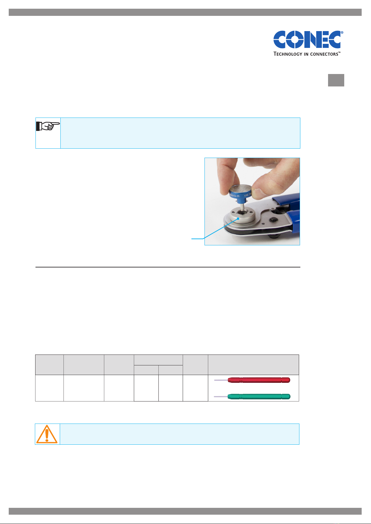
3 Premature opening of the crimping tool (emergency unlocking)
· To release the pawl, lightly press together the shanks of the tool.
· Use a suitable tool (e.g. screwdriver, Allen key etc.) and press the pawl upwards,
asshown in Figure 2.
· Open the tool.