ZU25201c_e.doc / Jan-12 Page 3 / 34
Table of Contents
1. Compatibility Hint ........................................................................................................ 4
2. Introduction.................................................................................................................. 5
3. Applicable Encoders and Sensors ................................................................................ 6
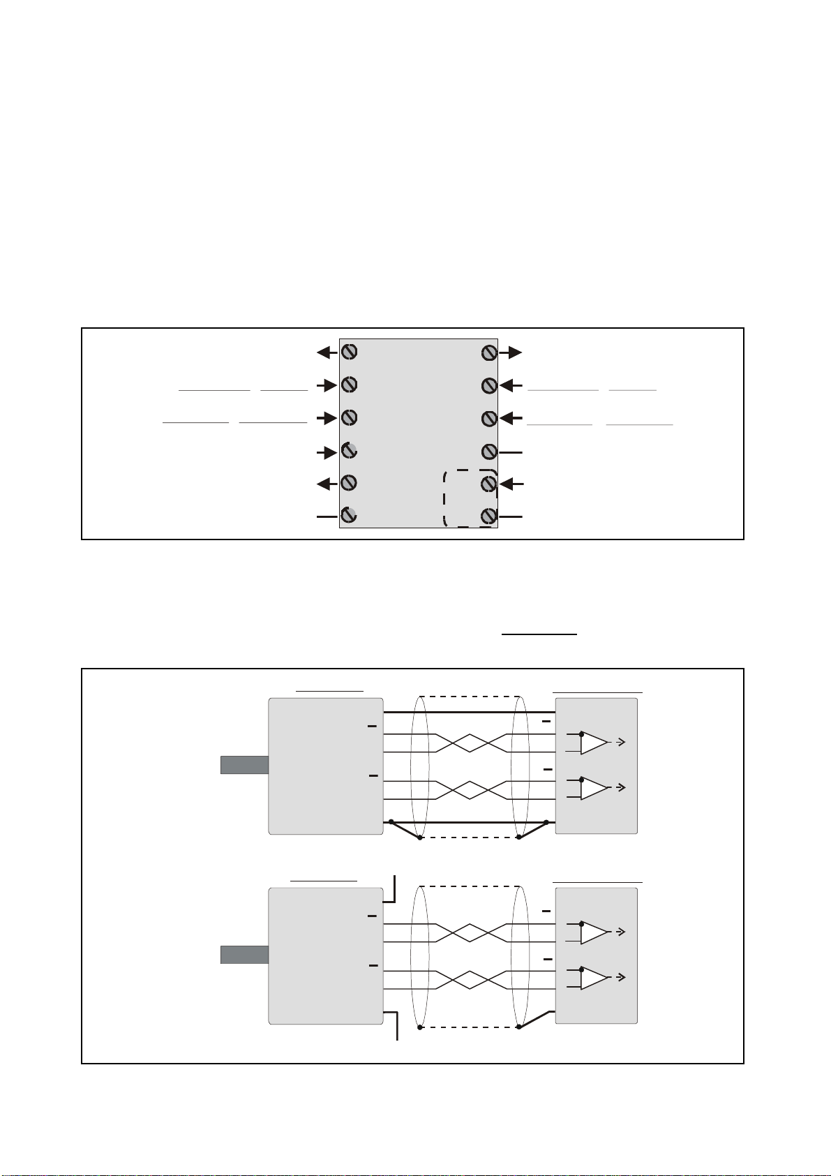
4. Terminal Assignment ................................................................................................... 7
4.1. Incremental encoders TTL / RS 422 ......................................................................7
4.2. Incremental encoder HTL / 12-30V........................................................................8
4.3. Proximity switches, photocells etc........................................................................8
4.4. Control Input..........................................................................................................8
4.5. Analogue outputs ..................................................................................................8
4.6. Serial interfaces ....................................................................................................9
5. DIL Switch Settings.................................................................................................... 10
5.1. Basic mode of operation and power-down memory setting...............................10
5.2. Impulse levels and symmetric / asymmetric input formats ................................11
5.3. Analogue output format ......................................................................................12
5.4. Selecting the RS232 or the RS485 serial interface.............................................13
5.5. Teach function, Test function, loading of default settings .................................13
6. Setup Procedure......................................................................................................... 14
6.1. Operation as single channel counter (without direction signal)
or as positional counter (with direction signal)...................................................15
6.2. Operation as a summing or differential counter with
two independent impulse inputs (A+B, A-B) .......................................................15
7. Readout of the Actual Counter State by Serial Communication................................ 16
8. PC Setup Using the OS3.2 Operator Software............................................................ 17
9. Displays and Softkeys................................................................................................ 18
10. Parameter Settings .................................................................................................... 19
11. Free Programmable Linearization ............................................................................... 25
12. Monitor Functions...................................................................................................... 27
13. Data Readout via Serial Interface .............................................................................. 29
14. Test Functions............................................................................................................ 30
15. Dimensions ................................................................................................................ 31
16. Technical Specifications ............................................................................................ 32
17. Parameter List............................................................................................................ 33
18. Setup Form................................................................................................................. 34