2CTVIMPO03_IG_en-GB_v1
PRIOR TO INSTALLATION
Read the manual prior to installation. Technical knowledge is necessary for installation. The place of installation
must be free of moisture and away from heat sources. Please ensure that the correct tools are used during the
installation to avoid damage to the vehicle or product. Connects2 can not be held responsible for the installation
of this product.
Important!
By law, watching moving pictures while driving is prohibited, the driver must not be distracted. We do not
accept any liability for material damage or personal injury resulting directly or indirectly, from installation
or operation of this product. This product should only be used while standing or to display xed menus or
rear-view-camera video when the vehicle is moving, for example the MP3 menu for DVD upgrades.
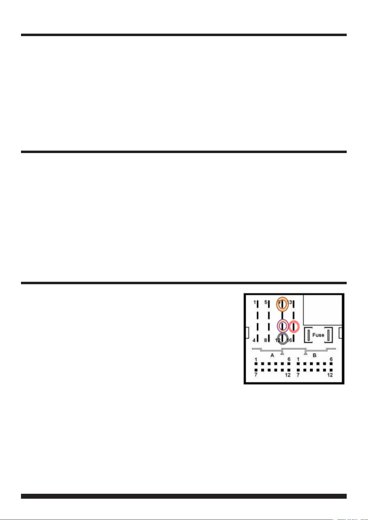
In Vehicle Connector (Quadlock)
● Red +12V Permanent Pin 15
● Black Ground Pin 12
●●Orange/Purple CAN High Pin 9
●●Orange/Brown CAN Low Pin 11
In Interface Connector (8 Pin Molex)
Yellow Pin 4 CAN-HIGH – connection to the head-unit
Blue Pin 3 CAN-LOW – connection to the head-unit
Yellow/Black Pin 8 CAN-HIGH – connection to the vehicle
Blue/Black Pin 7 CAN-LOW – connection to the vehicle
Red Pin 1 +12V permanent
Black Pin 5 Ground
Green Pin 6 Activation of the video-in-motion function
(+12V = TV-free activated)
White Pin 2 Trigger output (+12V DC 500mA)
PIN ASSIGNMENTS
SETTING THE DIP SWITCHES
Vehicle/ navigation DIP 1 DIP 2 DIP 3 DIP 4 DIP 5 DIP 6
Vehicles without rear-view camera ON* OFF OFF OFF ON ON
Vehicles with aftermarket rear-view camera ON* OFF OFF OFF ON ON
Vehicles with factory rear-view camera ON* ON OFF OFF ON ON
*If using the green cable to trigger the video in motion function, set DIP 1 to ‘OFF’


