LME49810 Audio Amplifier Module v1.0
Page 4
the CLPFLAG output is an open collector output, and it should never be left to float under normal operation. If
CLPFLAG pin is not used, then it should be connected through a resistor to a reference voltage so that IFLAG is
below 10mA. For example, a resistor of 1k can be used with a 5V reference voltage. This will give the IFLAG of
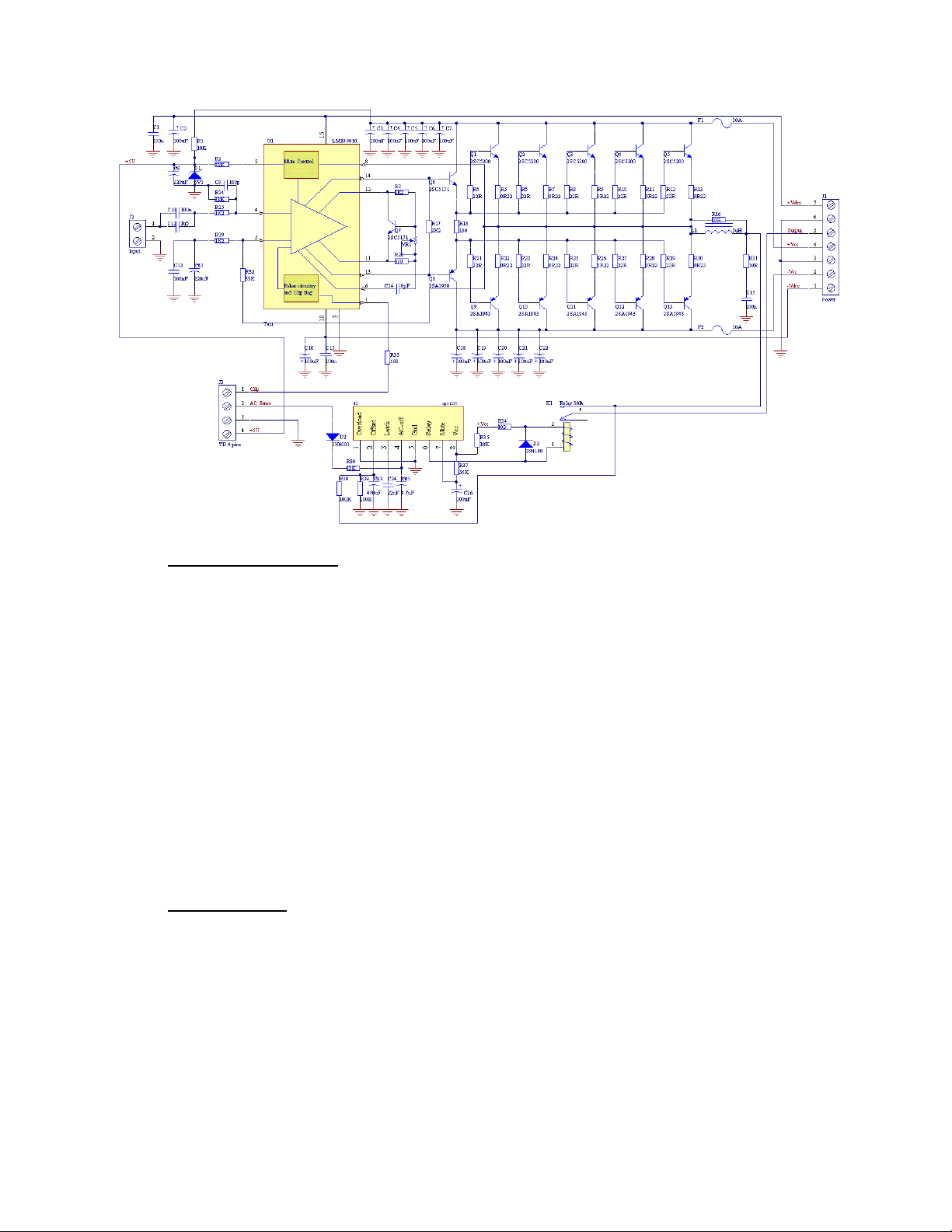
4.7mA. In a typical LED setup, if +5V reference voltage is not available, the following circuit using a Zener diode can
be used to power the CLPFLAG pin from the higher supply voltage rails of the LME49810. The power dissipation
rating of RZ will need to be at-least ½W if using a 5V Zener Diode. Alternately, the following basic formula can be
used to find the proper power rating of RZ : PDZ = (VCC -VZ)2/RZ (W). This formula can also be used to meet the
design requirements of any other reference voltage that the user desires.
Thermal Protection:
The LME49810 has a thermal protection scheme to prevent long-term thermal stress of the device. When
the temperature on the die exceeds 150°C, the LME49810 goes into thermal shutdown. The LME49810 starts
operating again when the die temperature drops to about 145°C, but if the temperature again begins to rise,
shutdown will occur again above 150°C. Therefore, the device is allowed to heat up to a relatively high
temperature if the fault condition is temporary, but a sustained fault will cause the device to cycle between the
thermal shutdown temperature limits of 150°C and 145°C. This greatly reduces the stress imposed on the IC by
thermal cycling, which in turn improves its reliability under sustained fault conditions. When in “play” mode, the
LME49810 draws a constant amount of current, regardless of the input signal amplitude. Consequently, the power
dissipation is constant for a given supply voltage and can be computed with the equation PDMAX = ICC * (VCC –
VEE). For a quick calculation of PDMAX, approximate the current to be 11mA and multiply it by the total supply
voltage (the current varies slightly from this value over the operating range). Since the die temperature is directly
dependent upon the heat sink used, the heat sink chose in the 300W and 500W LME49810 Amplifier versions has
low enough thermal resistance, so that thermal shutdown is not activated during normal operation.
Choosing the proper heatsink for the amplifier modules:
A Power Audio Amplifier must use a heat sink for it’s power dissipating components, such as Output
Power transistors, to keep the working temperature within normal limits. There are few aspects which must be
considered. First, the total dissipated power, which can be determined as a difference of power between the
Supply Power and the load delivered power. Such calculation is not very easy to make, so approximation can be
used. Class AB Power Audio Amplifiers has maximum theoretical Efficiency of about 70%. This value is almost
impossible to achieve in practice with good THD values and linearity. So, a compromise should be made, in favor of
the sound quality. This will lead to a lower electrical efficiency, especially at low Output Power. The main reason
for lower efficiency is the idle current and losses which occur in the signal and driving stages of the amplifier. The
maximum dissipated power, will occur at High Output Power Levels, when the amplifier drives low impedance
loads with high signal amplitude. It was calculated that with +/-61V supplies for the power stage, worst case
dissipation occurs at 170W into 8Ω load Impedance, of 145W. Most of this dissipated power is dissipated by the
output transistors, which share equally the dissipated power. However, audio signal power spectrum is much
poorer than the pure sine wave signal, usually just ⅛ of the power of the pure sine wave and with peaks of ⅓ of the
pure sine wave. In order to remove the heat generated by this power dissipation, an external heat sink with
thermal resistance of maximum 0.6 ˚C/W is required.
The choice of a heat sink for a high-power audio amplifier is made entirely to keep the die temperature at
a level such that the thermal protection circuitry is not activated under normal circumstances. The thermal
resistance from the die to the outside air, θJA (junction to ambient), is a combination of three thermal resistances,
θJC (junction to case), θCS (case to sink), and θSA (sink to ambient). The thermal resistance, θJC (junction to case),
of the LME49810 is 4°C/W. Using Thermalloy Thermacote thermal compound, the thermal resistance, θCS (case to
sink), is about 0.2°C/W. Since convection heat flow (power dissipation) is analogous to current flow, thermal
resistance is analogous to electrical resistance, and temperature drops are analogous to voltage drops, the power
dissipation out of the LME49810 is equal to the following: PDMAX = (TJMAX−TAMB) / θJA (2) where TJMAX = 150°C,
TAMB is the system ambient temperature and θJA = θJC + θCS + θSA. Once the maximum package power
dissipation has been calculated using Equation 2, the maximum thermal resistance, θSA, (heat sink to ambient)
in °C/W for a heat sink can be calculated. This calculation is made using Equation 3 which is derived by solving for
θSA from Equation 2. θSA = [(TJMAX−TAMB)−PDMAX(θJC +θCS)] / PDMAX (3). Again it must be noted that the
value of θSA is dependent upon the system designer's amplifier requirements. If the ambient temperature that the
audio amplifier is to be working under is higher than 25°C, then the thermal resistance for the heat sink, given all
other things are equal, will need to be smaller, resulting a larger heat sink needed.