Contacta Limited SecuriCom User guide

SecuriCom™
SPEECH TRANSFER SYSTEM
SYSTEM MANUAL
Contacta Limited
Head Office: Imex House, Sales Office: 50 Churchill Square,
VIP Trading Est., Anchor & Hope Lane, King’s Hill, West Malling,
Charlton, London SE7 7TE. UK Kent ME19 4YU. UK
Tel: 020 8858 2123 • Fax: 020 8858 4866 Tel: 01732 223900 • Fax: 01732 223909

Contents Page
4Product Overview
5System Components
6System Options
7Configuration: Bridge Bar System
8Configuration: Surface Mounting System
9Configuration: Flush Mounting System
10 Installation
13 Fitting Instructions: Bridge Bar System
14 Fitting Instructions: Surface Mounting System
15 Fitting Instructions: Flush Mounting System
16 Fitting Instructions: Staff Unit
17 Operation: Instructions
18 Operation: Optional Hearing Aid Induction Loop
19 Other Contacta Products
SECURICOM SPEECH TRANSFER SYSTEM CONTENTS
3

Product Overview TheSecuriComSpeechTransferSystemisatwo-wayintercomspecificallydesignedtoaid
communications where normal speech is impaired by the use of glass security screens or
other similar barriers.
Every system is controlled and powered individually and operates on a stand-alone basis.
Each system comprises a twin-channel audio amplifier, power supply unit, a microphone
and speaker for the staff and a microphone and speaker for the customer. The microphone
and speaker modules are supplied in various formats to enable the system to be installed
in differing locations.
The system operates on an “Open Duplex” basis, i.e. microphones and speakers are live
simultaneously, similar to a telephone, with no manual or automatic switching of the voice.
This means that clipping of speech is not encountered whilst still allowing users to
operate the system “Hands-Free”. Sophisticated electronic circuitry in the amplifier and
purpose designed speaker and microphone modules ensure that the risk of acoustic
coupling or “Feedback” is kept to a minimum.
Securicom also offers an induction loop facility which is built into the system for users of
hearing aids.
SecuriCom is offered either in a system kit format, or as individual modules, thus allowing
maximum flexibility to “tailor” systems to individual requirements.
SECURICOM SPEECH TRANSFER SYSTEM PRODUCT OVERVIEW
4

Part No. Amplifier Power Supply Staff Unit Customer Unit
STS-K001 STS-A20 STS-P41 or STS-F70 STS-B80
STS-P42 Staff Unit Audio Bridge
1a Bridge Bar System with Loop Facility
STS-K001-L STS-A30 STS-P43 STS-F70 STS-B80
Staff Unit Audio Bridge
Induction Loop
IL-E97 Induction Loop Sign
Part No. Amplifier Power Supply Staff Unit Customer Unit
STS-K002 STS-A20 STS-P41 or STS-F70 STS-M54 Microphone
STS-P42 Staff Unit and STS-S60 Speaker
2a Surface Mounting System with Loop Facility
STS-K002-L STS-A30 STS-P43 STS-F70 STS-M54 Microphone
Staff Unit and STS-S60 Speaker
Induction Loop
IL-E97 Induction Loop Sign
SECURICOM SPEECH TRANSFER SYSTEM SYSTEM COMPONENTS
5
1 Bridge Bar System
2 Surface Mounting System
Part No. Amplifier Power Supply Staff Unit Customer Unit
STS-K003 STS-A20 STS-P41 or STS-F70 STS-M56 Microphone
STS-P42 Staff Unit and STS-S61 Speaker
3a Flush Mounting System with Loop Facility
STS-K003-L STS-A30 STS-P43 STS-F70 STS-M56 Microphone
Staff Unit and STS-S61 Speaker
Induction Loop
IL-E97 Induction Loop Sign
3 Flush Mounting System
The STS-F70 Staff Unit comprises loudspeaker and close talking gooseneck microphone
in one discreet unit. An On/Off button mutes the microphone if required for privacy reasons.
4 Staff Unit (common to all systems)

SECURICOM SPEECH TRANSFER SYSTEM SYSTEM OPTIONS
6
Customer Options
Customer’s side 1
Surface mounting components
STS-M54 Microphone
and STS-S60 Loud speaker
Customer’s side 2
Flush mounting components
STS-M56 Microphone
and STS-S61 Loud speaker
Customer’s side 3
Surface mounting components
STS-B80 Audio Bridge
Close talking Microphone
and twin Loud speakers
Staff Option
Staff side 1
STS-F70 Staff Unit
STS-M54 Microphone STS-S60 Speaker
Cash Tray
contacta
Hearing loop is installed
here. Switch your hearing
aid to the T-position.
Optional IL-E93/94/95 Induction Loop
STS-M56 Microphone STS-S61 Speaker
Cash Tray
contacta
Hearing loop is installed here.
Switch your hearing aid to the
T-position.
Optional IL-E93/94/95 Induction Loop
Cash Tray
contacta
Hearing loop is installed here.
Switch your hearing aid to the
T-position.
Speaker
Speaker
STS-B80 Audio Bridge
with goose neck close
speaking microphone
Optional IL-E93/94/95 Induction Loop
Cash Tray
contacta
Hearing loop is installed here.
Switch your hearing aid to the
T-position.
STS-F70 Staff Unit comprising close speaking
microphone, loudspeaker and mute switch
Customer side
Staff side

SECURICOM SPEECH TRANSFER SYSTEM CONFIGURATION
Security Screen
STS-P41/42
Power
Supply
Unit
STS-B80 Customer Audio Bridge
Customer
Staff
STS-A20 Amplifier
STS-F70 Staff Unit
Cabling
A: From Amplifier to
Bridge - Twin
‘Figure of eight’
(2 No.) and one
single core
shielded
B: From Amplifier to
Staff Unit - Combined
speaker and Mic.
cables
220/240 VAC
50Hz
CUSTOM STAF
POWE
contacta
STS-A 20/30
1: Bridge Bar System
Customer: Customer Audio Bridge
Staff: Staff Unit
Security Screen
STS-P43 Power
Supply Unit
STS-B80 Customer Audio Bridge
Customer
Staff
STS-A30 Amplifier
STS-F70 Staff Unit
220/240 VAC
50Hz
Cabling
A: From Amplifier to
Bridge - Twin
‘Figure of eight’
(2 No.) and one
single core
shielded
B: From Amplifier to
Staff Unit - Combined
speaker and Mic.
cables
C: From Amplifier to
Induction Loop -
Twin wire cable
IL-E93/94/95
Induction
Loop
Aerial
CUSTOM STAF
POWE
contacta
STS-A 20/30
1a: Bridge Bar System with
Induction Loop Aerial
Customer: Customer Audio Bridge
Induction Loop Aerial
Staff: Staff Unit
7

SECURICOM SPEECH TRANSFER SYSTEM CONFIGURATION
Security Screen
STS-P41/42
Power
Supply
Unit
STS-M54 Microphone
Customer
Staff
STS-A20 Amplifier
STS-F70 Staff Unit
Cabling
A: From Amplifier to
Speaker - Twin
‘Figure of eight’
B: From Amplifier to
Microphone -
Single core shielded
C: From Amplifier to
Staff Unit - Combined
speaker and Mic.
cables
220/240 VAC
50Hz
STS-S60 Speaker
CUSTOM STAF
POWE
contacta
STS-A 20/30
2: Surface Mounting System
Customer: Microphone and Speaker
Staff: Staff Unit
Security Screen
STS-P43 Power
Supply Unit
STS-M54 Microphone
Customer
Staff
STS-A30 Amplifier
STS-F70 Staff Unit
220/240 VAC
50Hz
Cabling
A: From Amplifier to
Speaker - Twin
‘Figure of eight’
B: From Amplifier to
Microphone - Single
core shielded
C: From Amplifier to
Staff Unit - Combined
speaker and Mic.
cables
D: From Amplifier to
Induction Loop -
Twin wire cable
IL-E93/94/95
Induction
Loop
Aerial
STS-S60 Speaker
CUSTOM STAF
POWE
contacta
STS-A 20/30
2a: Surface Mounting System with
Induction Loop Aerial
Customer: Microphone and Speaker
Induction Loop Aerial
Staff: Staff Unit
8

SECURICOM SPEECH TRANSFER SYSTEM CONFIGURATION
Security Screen
STS-P41/42
Power
Supply
Unit
STS-M56 Microphone
Customer
Staff
STS-A20 Amplifier
STS-F70 Staff Unit
Cabling
A: From Amplifier to
Speaker - Twin
‘Figure of eight’
B: From Amplifier to
Microphone - Single
core shielded
C: From Amplifier to
Staff Unit - Combined
speaker and Mic.
cables
220/240 VAC
50Hz
STS-S61 Speaker
CUSTOM STAF
POWE
contacta
STS-A 20/30
3: Flush Mounting System
Customer: Microphone and Speaker
Staff: Staff Unit
Security Screen
STS-P43 Power
Supply Unit
Customer
Staff
STS-A30 Amplifier
STS-F70 Staff Unit
220/240 VAC
50Hz
Cabling
A: From Amplifier to
Speaker - Twin
‘Figure of eight’
B: From Amplifier to
Microphone - Single
core shielded
C: From Amplifier to
Staff Unit - Combined
speaker and Mic.
cables
D: From Amplifier to
Induction Loop -
Twin wire cable
IL-E93/94/95
Induction
Loop
Aerial
STS-M56 Microphone STS-S61 Speaker
CUSTOM STAF
POWE
contacta
STS-A 20/30
3a: Flush Mounting System
with Induction Loop Aerial
Customer: Microphone and Speaker
Induction Loop Aerial
Staff: Staff Unit
9

System Components
Siting and Installing the Amplifier
Siting and Installing
Microphones and Speakers
1. STS A20 audio amplifier (or A30 version for loop facility)
2. STS-P41/P42 12V DC power supply (or P43 PSU for loop facility)
3. STS-F70 Staff Unit comprising close speaking microphone and loud speaker
4. A microphone for the Customer
5. A loudspeaker for the Customer
6. Induction Loop Aerial (optional)
N.B. Microphones and Loudspeakers are available in flush or surface mounting formats.
The STS-F70 Staff Unit for the staff side is supplied as standard. An alternative option comprising
separate microphones and loudspeakers is also available.
A Customer Audio Bridge with twin surface mounted loudspeakers and a centrally fitted close
speaking microphone is available for the Customer’s side.
Each SecuriCom system requires one Audio Amplifier (STS-A20 or STS-A30) with its associated Power
Supply (STS-P41/42 or STS-P43). The Amplifier connects on a plug and socket basis to other system
components via individual cables.
TheAmplifier shouldbe mountedon aflat surfacewithin closeproximity tothe othersystem com-
ponents and conveniently to hand for the operator. For example, on the staff side under the desk-top
or counter-top would be suitable. Ensure there is also access to the Microphone and Induction Loop
gain controls located on the side of the amplifier and also to the rear connection sockets before fix-
ing. Twin flanges each with two screw holes are formed at the top of the amplifier housing.These are
used to fix the amplifier under the counter top with small self tapping screws.. The Amplifier housing
need not be opened as all connections are external.
Customer Microphones and Loud Speakers may be flush or surface mounted depending on individual
requirements.Seefollowing pagesforfitting instructions.Surfacemountedcomponents arebestsited
atthejunction betweenthe counter-topandthe glasspartition.Forbestperformance, theMicrophone
should be mounted at least 30 centimetres away from the Loudspeaker. Each component comes with
a 3 metre lead and two-way plug. It is advisable to remove the plug before fixing as this enables a
neater installation to be achieved using smaller diameter holes through which to feed the cables.
However, the cables and plugs must be re-connected correctly or the system will not operate. If in
doubt, identify and mark the wires before disconnecting the plug(s).
SECURICOM SPEECH TRANSFER SYSTEM INSTALLATION
Security Screen
Power
Supply
Unit
STS Amplifier mounted
below counter-top
220/240
VAC
50Hz
Cash Tray
Minimum distance between loudspeaker
and microphone 30 cms
Staff side
Customer side
Typical SecuriCom set up using flush mounted components on the Customer’s side
and combined Staff Unit for Staff.
CUSTOM STAF
POWE
contacta
STS-A 20/30
STS-F70
Staff Unit
10

Siting and Installing the Staff Unit
Amplifier Connections
Connecting Components
to the Amplifier
Controls
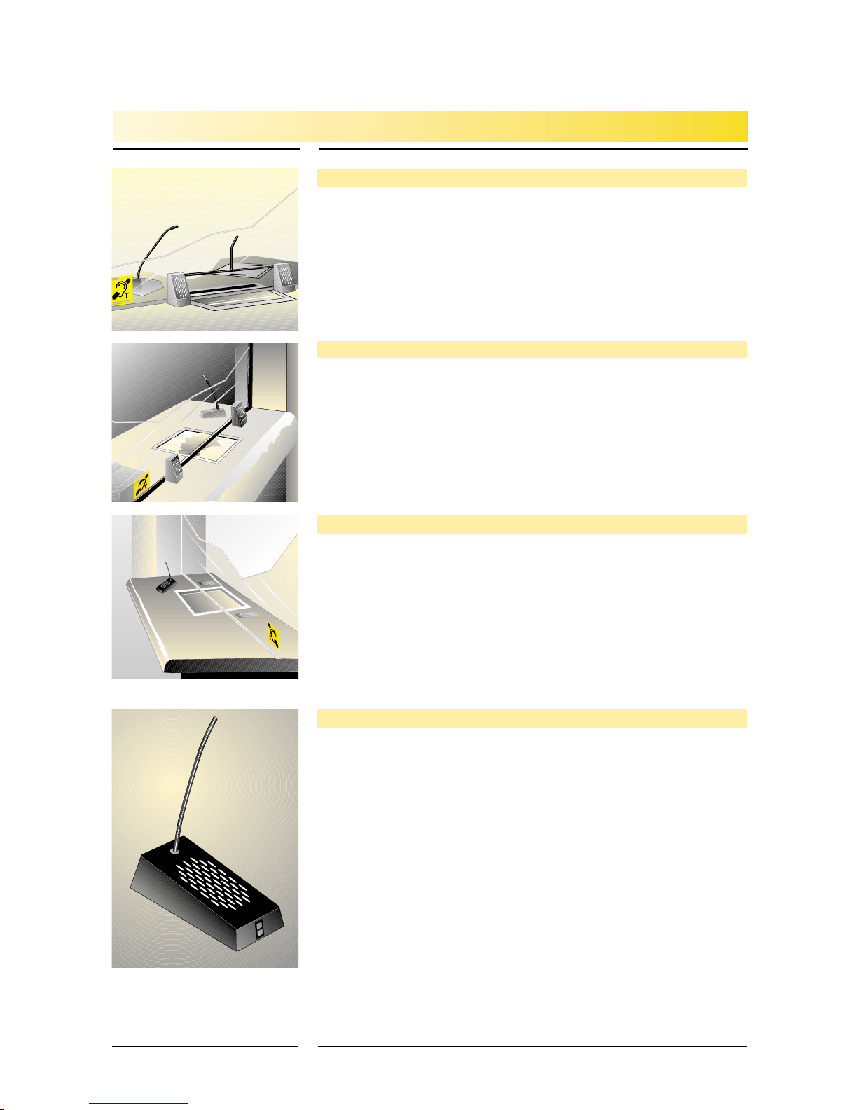
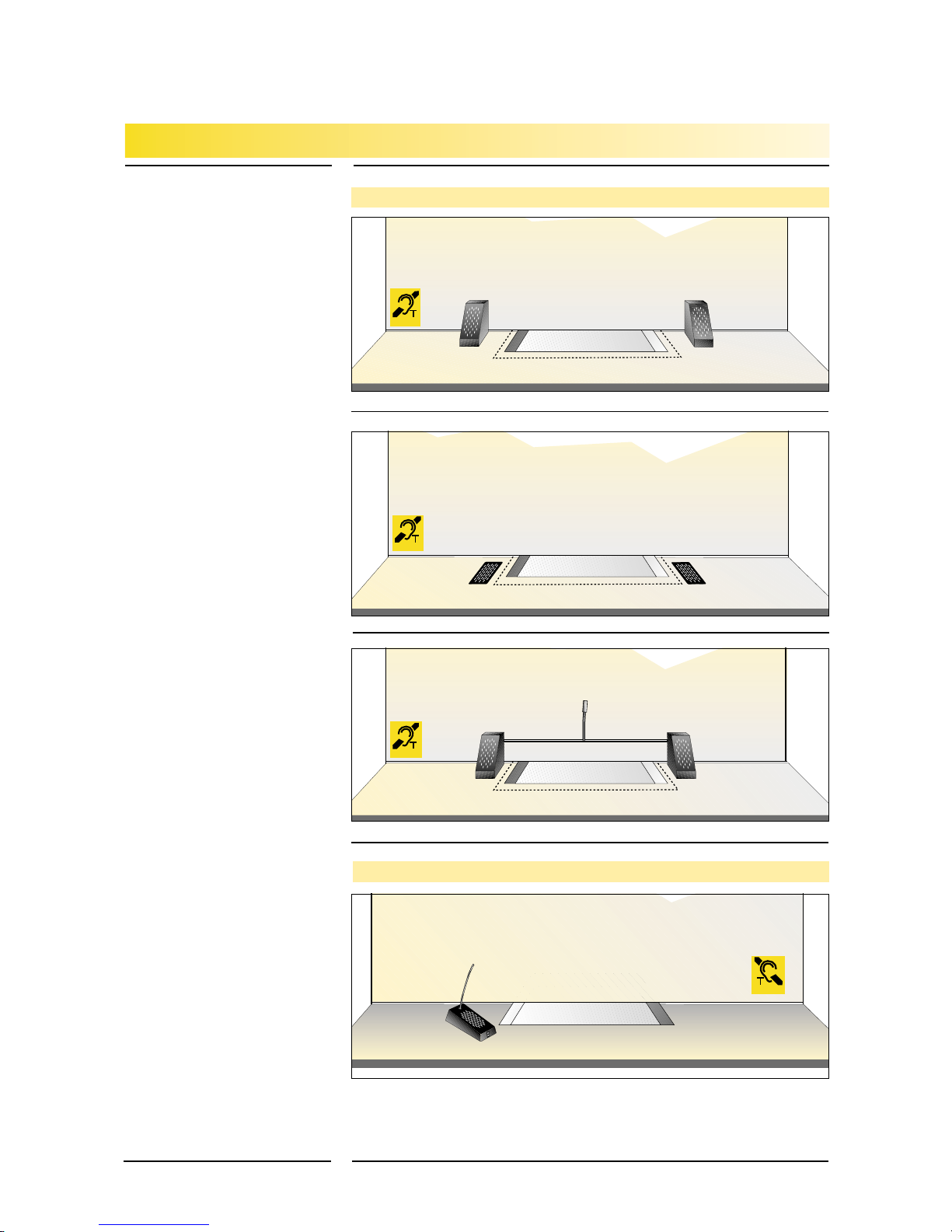
The STS-F70 Staff Unit is a self standing module for the Staff Side. It should be placed conveniently on
the counter top so the cashier can hear the loudspeaker and talk into the gooseneck microphone to
the customer. The microphone is of the close talking type so background noise is not picked up. A
‘Mute’ switch is located on the front of the Staff Unit. In the absence of a cable port, a suitably sized
hole should be drilled into the counter top at the rear of the Staff Unit to take the reinforced cable.
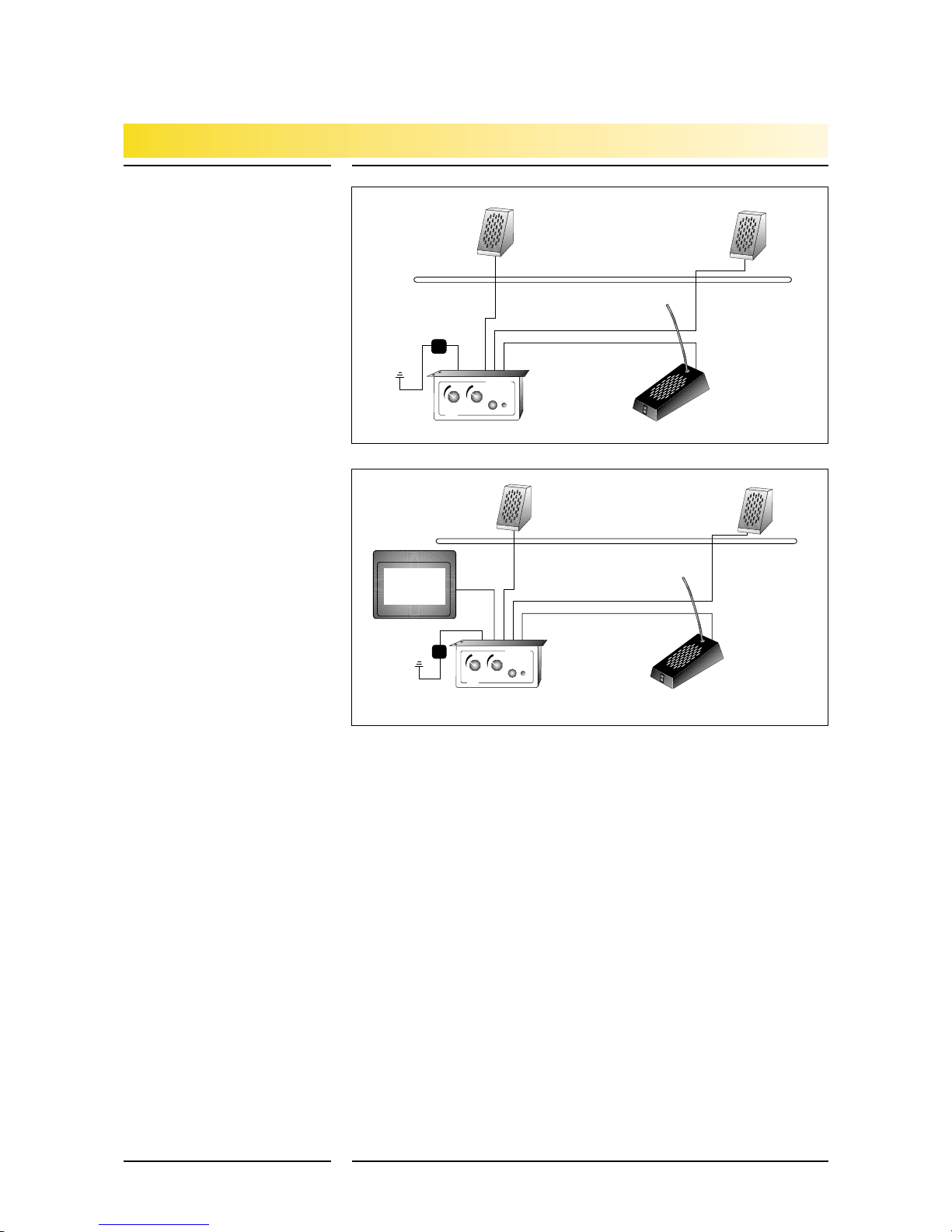
Disconnect the 2 two-way plugs before introducing the cables for a neater installation. Ensure these
are re-connected correctly or the system will not operate.
1 LED/Tone (+) 8 Staff Mic 2 (screen) 15 Staff Speaker 2 (+)
2 LED/Tone (-) 9 Customer Mic 2 (+) 16 Staff Speaker 2 (-)
3 Staff Unit Mic 1 (+) 10 Customer Mic 2 (screen) 17 Customer Speaker 2 (+)
4 Staff Unit Mic 1 (screen) 11 Staff Unit Speaker (+) 18 Customer Speaker 2 (-)
5 Customer Mic 1 (+) 12 Staff Unit Speaker (-) 19 Induction Loop Aerial (+)
6 Customer Mic 1
(screen)
13 Customer Speaker 1 (+) 20 Induction Loop Aerial (-)
7 Staff Mic 2 (+) 14 Customer Speaker 1 (-)
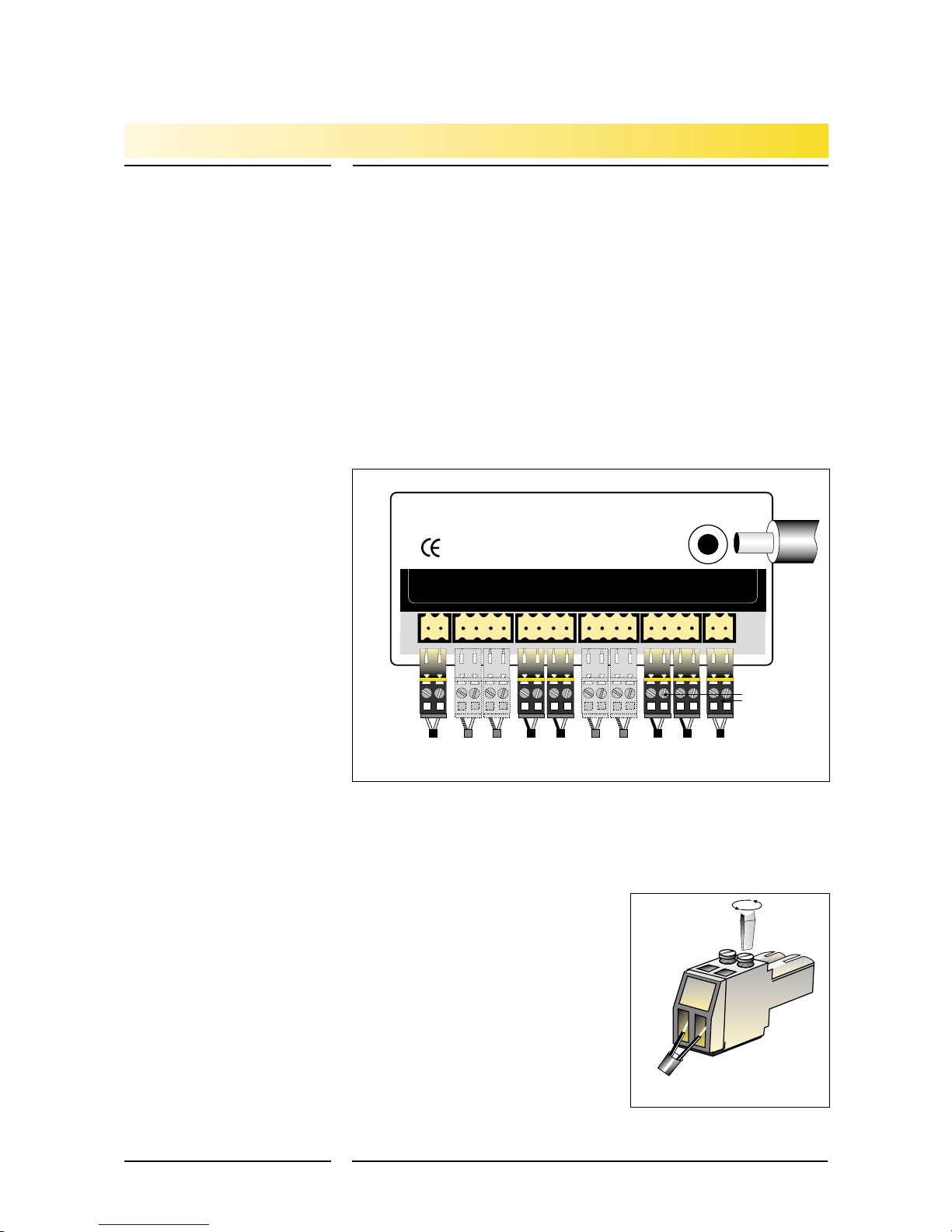
Each component (Microphone, Loudspeaker, Staff Unit or Induction Loop) comes fitted with two-way
connection plug(s) which locate into the appropriate socket(s) at the rear of the Amplifier. The plugs
connect to the cables by screw terminal connections so cables can be removed and fed through small,
neatapertures foranunobtrusive, discreteinstallation. However, thecablesand plugsmust bere-con-
nected correctly or the system will not operate. If in
doubt,mark the wiresbefore disconnectingthe plug(s). If
there is a suitable cable port on the cashiers side, the
Staff Unit cables can be diverted through this without the
need to remove and re-connect the 2 two-way plugs.
Controls are provided on the front of the Amplifier. The
latching push switch marked ‘power’ switches the unit
on or off, a red LED indicates when the unit is on. Two
rotary volume controls marked ‘customer’ and ‘staff’
adjust output from the loudspeakers. The volume of the
system may be adjusted by turning the rotary volume
controls clockwise (to increase the level of sound) or
anticlockwise (to decrease the level of sound).
SECURICOM SPEECH TRANSFER SYSTEM INSTALLATION
Contacta Communication Systems Limited
Tel: 0181 858 2123
Power in
Connection
to Induction
Loop Aerial
Induction Cust Staff Cust Staff Cust Staff Cust Staff
Loop Spk 2 Spk 2 Spk 1 Spk 1 Mic 2 Mic 2 Mic 1 Mic 1 LED Tone
-+ -+-+ -+- + Sc+Sc+ Sc+Sc+- +
20 19 18 17 16 15 14 13 12 11 10 9 8 7 6 5 4 3 2 1
Connection
plugs
+
-+
-+
-+
-+
-+++
Sc ++
-
Connection
to LED or
tone signal
(optional)
Optional
connections
to second
microphones
Connect
to
customer
loud
speaker
Optional
connections to
second
loudspeakers
Rear of Amplifier showing two-way connections for components
Sc
Sc Sc
Connect
to Staff
Unit
Connect
to
customer
micro-
phone
Connect
to Staff
Unit
Enlarged drawing of two-way plug that connects
components to the rear of the amplifier
Positive +
Negative -
or
Screened
Cable
11

Adjusting the System
Induction Loop Facility
Adjusting the
Induction loop facility
Controls for adjusting the
microphone gains are located
alongone side ofthe amplifier.
Please note these are factory
set prior to despatch and
should require no adjustment
unless exceptional audio con-
ditions are encountered. To
increase or decrease the gain
on either the Customer’s
Microphone or the Staff
Microphone, first make sure
that both volume controls on
the front of the amplifier are
turned fully clockwise for
maximum volume. Then turn
the appropriate gain poten-
tiometer clockwise (to
increase gain) or anticlock-
wise (to decrease gain) using
the trim tool supplied.
Substantial changes in the
audio levels can be achieved
by relatively minor adjust-
ments of the gain controls.
Should feedback occur whilst
making adjustments, turn the gain controls anticlockwise until the feedback disappears and the
desired sound level obtained. The set-up switch is factory set and should not be altered.
If the SecuriCom System has been supplied with optional Induction Loop Facility, the package will
contain an STS A30 audio amplifier, a P43 Power Supply Unit, a suitable Induction Loop Aerial, (either
IL-E93, IL-E94 or IL-E95) and a self adhesive yellow induction loop sign (IL-E97). The principle of the
system is to transmit sound via an electro-magnetic field which is picked up and amplified by a tele-
coil fitted inside customers’ hearing aids.
Correct positioning of the Induction Loop Aerial is critical to ensure the loop performs to its full
potential.It shouldbe fixedunderthe desk-topor countercentrally socustomers wearinghearingaids
receive the signal. In the case of the IL-E94 (Loop Pad Aerial), for best results, this can be folded so
that half is mounted horizontally under the counter and the other half mounted vertically, facing the
customer. Make sure that the Induction Loop self adhesive yellow sticker is displayed in a prominent
position.
The Induction Loop Aerial connects to terminals
19 and 20 on the Amplifier using the appropriate plug
and socket.
The control for adjusting the Induction Loop gain is
located on the side of the amplifier and output may be
adjusted by using the trim tool and an induction loop
tester. Turn the gain potentiometer clockwise (to
increase gain) or anticlockwise (to decrease gain).
SECURICOM SPEECH TRANSFER SYSTEM INSTALLATION
Fix Induction
Loop pad to
underside of
counter in
horizontal and
vertical plane
CUSTOMER
STAFF
contacta
STS-A20/30
power
Side view of the Securicom Amplifier showing potentiometers for adjusting
gains on the Microphones and the Induction Loop Aerial
Volume
Controls
Tone Set-up
Switch Staff
Mic. Customer
Mic. Induction
Loop Gain On/off
switch
12
Adjustments can be made to speech and
induction loop outputs by the additional
potentiometers located on the side of the
amplifier
Customer volume control
Staff volume control
On/Off switch
and power LED
CUSTOMERSTAFF
contacta
STS-A 20/30
power

Bridge Bar System STS-K001
STS-B80 Audio Bridge
STS-F70 Combined Staff Unit
Figure 1
Figure 2
Figure 3
Figure 4
SECURICOM SPEECH TRANSFER SYSTEM FITTING INSTRUCTIONS
Cash
Surface mounted Bridge
Bar pod
(left hand position
accommodates all cabling)
Glass security screen
Drill
suitable
hole in counter
for cables
Drill twin pilot
holes for fixing screws
Surface mounted
Bridge Bar pod
(right hand)
Cash Tray
Knurled point cup
screws for fixing
bridge bar
625 mm wide
Cash Tray
Glass security screen
Tighten knurled
point cup screws to
fix bridge bar at
both ends
All cables exit left
through counter top
Bridge Bar with
Gooseneck
Microphone
Use small pipe cutter if
cutting bridge bar to
length to avoid damage
to internal cables
Cash Tray
Glass security screen
Connect first
loudspeaker and fit
to pod
Connect second
loudspeaker and fit to
pod
Cash Tray
Glass security screen
STS-F70 Staff Unit
Retaining m/screw
Surface mounted Bridge Bar system
utilising twin loud speakers and
gooseneck microphone
Customer side
Use existing cable port or drill
suitable hole through counter
top to feed cable
from Staff Unit
Loudspeaker
Microphone
Loudspeaker
13

Surface Mounting STS-K002
STS-M54 Microphone
STS-S60 Speaker
STS-F70 Combined Staff Unit
Figure 1
Figure 2
Figure 3
Figure 4
SECURICOM SPEECH TRANSFER SYSTEM FITTING INSTRUCTIONS
Cash Tray
Surface mounted speaker
or
microphone pod
Drill
suitable
hole in counter
for cable
Drill twin
pilot holes for
fixing screws
Glass security screen
Cash Tray
Glass security screen
Fix pod to
counter top with
2 (No) self
tapping screws
Cash Tray
Glass security screen
Run cables
from speaker or microphone through
counter top and fit unit to pod. Secure
with 2 (No) machine screws
Surface mounted loud
speaker and microphone with
staff unit
Cash Tray
Glass security screen
Loudspeaker
Microphone
STS-F70
Staff Unit
Use existing cable port or drill
suitable hole through counter
top to feed cable
from Staff Unit
Customer side
Staff side
14

Flush Mounting STS-K003
STS-M56 Microphone
STS-S61 Speaker
STS-F70 Combined Staff Unit
Figure 1
Figure 2
Figure 3
Figure 4
SECURICOM SPEECH TRANSFER SYSTEM FITTING INSTRUCTIONS
Flush mounted
Loudspeaker Prepare counter top
by drilling suitably
sized corner holes to
acommodate jig saw
blade
Cash Tray
Security glass screen
Flush mounted
Microphone Drill pilot holes to
suit fixing screws
120mm
98mm
107mm
52mm
55mm
65mm
Dimensions of cutout for both
Loudspeaker and Microphone
Clearance hole
for obtruding
stud
Jigsaw blade
Corner radii to suit jigsaw blade
Glass security screen
Customer side
Cash tray
STS-F70 Staff Unit
Use existing cable port or drill
suitable hole through counter
top to feed cable
from Staff Unit
Flush mounted loud speaker
and microphone with staff unit
Loudspeaker
Microphone
15

Staff Unit
STS-F70 Combined
Microphone
andSpeaker
Figure 1
Figure 2
Figure 3
SECURICOM SPEECH TRANSFER SYSTEM FITTING INSTRUCTIONS
Cash Tray
contacta
Hearing loop is installed here.
Switch your hearing aid to the
T-position.
STS-F70 Staff Unit comprising close speaking
microphone, loudspeaker and mute switch
1 foot (30 cms)
Cash Tray
Counter Top Customer’ Side
Security Glass Screen
Staff Unit
Cable port
Cash tray
Glass security screen
Customer side
Use cable port
or drill suitable hole
through counter top to
feed cable from Staff Unit STS-F70 Staff Unit
Staff side
16

Operating Instructions
• Switch the system “ON” by depressing the black push-button on the front of the
amplifier which is usually located under the counter. A red light, or L.E.D., will light up
signifying that the system is “ON”.
• Position the Staff Unit so that the gooseneck microphone is approximately 1 foot
(30cms) from your head. Face the microphone and speak normally from your usual
seating position.
• To increase the volume of the speech level you hear on the staff side, turn the rotary
controlmarked“STAFF”onthefrontoftheamplifier inaclockwisedirection.Toreduce
the volume, turn the control in the opposite, anticlockwise direction.
• To increase the volume of the speech level for the customer, turn the rotary control
marked “CUSTOMER” on the front of the amplifier in a clockwise direction. To reduce
the volume, turn the control in the opposite, anticlockwise direction.
• Ifa Staff Unithas beenfitted, thiswill havea “MicrophoneMute“ facilitybutton.When
activated, the latter will not transmit any sound from the Staff side. This may be used
for privacy purposes.
• SomeSecuriCom systems aresupplied withan InductionLoop facilityforthebenefit of
customers who wear hearing aids. To take advantage of this facility, the hearing aid
usershouldswitch their device tothe “T” position.A signsupplied with thesystem will
inform the hearing aid user that the facility is available. It is therefore important that
this sign is displayed in a prominent position.
• To turn the SecuriCom system “OFF”, release the black push-button on the front of the
amplifier.
SECURICOM SPEECH TRANSFER SYSTEM OPERATION
17
The SecuriCom Amplifier showing controls
Customer volume control
Staff volume control
On/Off switch
and power LED
CUSTOMERSTAFF
contacta
STS-A 20/30
power

SECURICOM SPEECH TRANSFER SYSTEM OPERATION
18
To meet obligations under the 1995 Disability Discrimination Act, an Induction Loop System
has been installed in this area for the benefit of Hearing Aid Users. To use this facility,
customers should switch their Hearing Aids to the ‘T’ Position. Background noise will be
less obtrusive and customers will hear the member of staff more clearly.
• The System is ‘ON’ at all times.
• Staff’s voice is picked up by the Staff Unit on the staff side.
• Customers will receive the maximum signal from the induction loop
provided they are within the shaded area shown above.
• Confirmation that a System is installed is displayed by an
Induction Loop Sign.
NOTE: THE SOUND LEVEL WILL HAVE BEEN ‘SET’ FOR THE
AVERAGE CUSTOMER. VOLUME CAN BE ADJUSTED BY THE
HEARING AID USER’S OWN VOLUME CONTROL.
contacta
Counter Top Clerk’ Side
Cash Tray
Induction Loop hidden below counter
Flush
Microphone
Flush
speaker
STS-F70
Staff Unit
Counter Top Customer’ Side
Security Glass Screen
Shaded section
represents range of
induction loop aerial
Suggested text for notice
displayed to customers
Instructions for Use
Optional Hearing Aid Induction Loop

SECURICOM SPEECH TRANSFER SYSTEM OTHER CONTACTA PRODUCTS
19
Contacta Q-Control
Contacta InfoLoop
Hearing Aid Induction Loop Systems
Q-Control from Contacta is a sophisticated queue management system for up to 16 staff
positions. It communicates visually and audibly with your customers, directing them to the
next available position in an orderly manner with no confusion. As a result, quality of
service is improved and staff can concentrate solely on their immediate customer’s
requirements. Q-Control is particularly effective where financial and confidential matters
are being dealt with.
Research has indicated that customers are happier and more relaxed with an
efficient queue management system. It’s fairer because they can be served in the correct
order, there’s no jostling and the next customer is not ‘breathing down their neck’, – a
safety factor that is particularly appreciated when money is changing hands.
At the centre of the system, and usually located in a prominent position at the head of the
queue, is the Main Display Board. This provides audible and visual information concerning
the queue direction. The visual information is shown on three LED panels. The Central
Control Module contains all central system circuitry and is linked to the other system
components by the system cable network.
Each staff position is identified by an LED display denoting the counter position number. In
addition each member of the staff has a switch which can be depressed when the position
becomes free.
The Q-Control system interfaces with other Contacta equipment such as the SecuriCom
Speech Transfer System and InfoLoop Induction Loop system to provide the optimum in
customer care at service and cashier positions.
The InfoLoop Induction Loop System from Contacta is a loop based voice amplification
systemto assist customers whouse hearingaids.By simply switchingtheir aidoverto the
“T” or “Telecoil” position, their aid reduces air transmitted sound signals and receives
speech via the Induction Loop and the Telecoil located within the hearing aid. InfoLoop
gives clear hearing and understanding for those with hearing disabilities. It is designed for
ticket offices, bank and building society counters, bureaux de change and interview and
meeting rooms. InfoLoop is the perfect answer for high background noise areas where
confidential discussions take place or when clear speech is restricted by glass security
screens; traditionally “difficult” areas for hearing aid users.
Each system is controlled and powered individually and operates on a stand-alone basis
The system essentially comprises a microphone, an amplifier which drives the induction
loop and a power supply unit. Various types of microphones and loop aerials are
available to meet the precise, acoustic and logistic needs of each location.
In addition, a portable, self powered Induction Loop System is available for more flexible
use.
Contacta Q-Control system in use at Tottenham
Hotspur’s Ticket Office

Head Office: Imex House, VIP Trading Estate,
Anchor & Hope Lane, Charlton, London SE7 7TE.
Tel: 020 8858 2123 • Fax: 020 8858 4866
Registered in England No. 979640
Sales Office: 50 Churchill Square, King’s Hill,
West Malling, Kent ME19 4YU.
Tel: 01732 223900 • Fax: 01732 223909
Founded in 1970
FM 36903
COMMUNICATION SYSTEMS
•
SECURITY SOLUTIONS
LIMITED
Table of contents