HLD3 INSTALLATION
Contents
Components .................................................................................................................................................................... 1
Loop Installation Options ................................................................................................................................................ 2
Loop Pad Installation....................................................................................................................................................... 3
Loop Wire Installation...................................................................................................................................................... 4
HLD3 Driver Connection................................................................................................................................................. 5
Overview................................................................................................................................................................... 5
...................................................................................................................................................................................... 5
Optical ...................................................................................................................................................................... 5
Auxiliary..................................................................................................................................................................... 5
Installation with a Set Top Box or Sound Bar (e.g. Sky, Virgin, TiVo) ........................................................................ 6
Optical ...................................................................................................................................................................... 6
Auxiliary..................................................................................................................................................................... 6
Connecting To an Alternative Sound Source ............................................................................................................... 7
Optical ...................................................................................................................................................................... 7
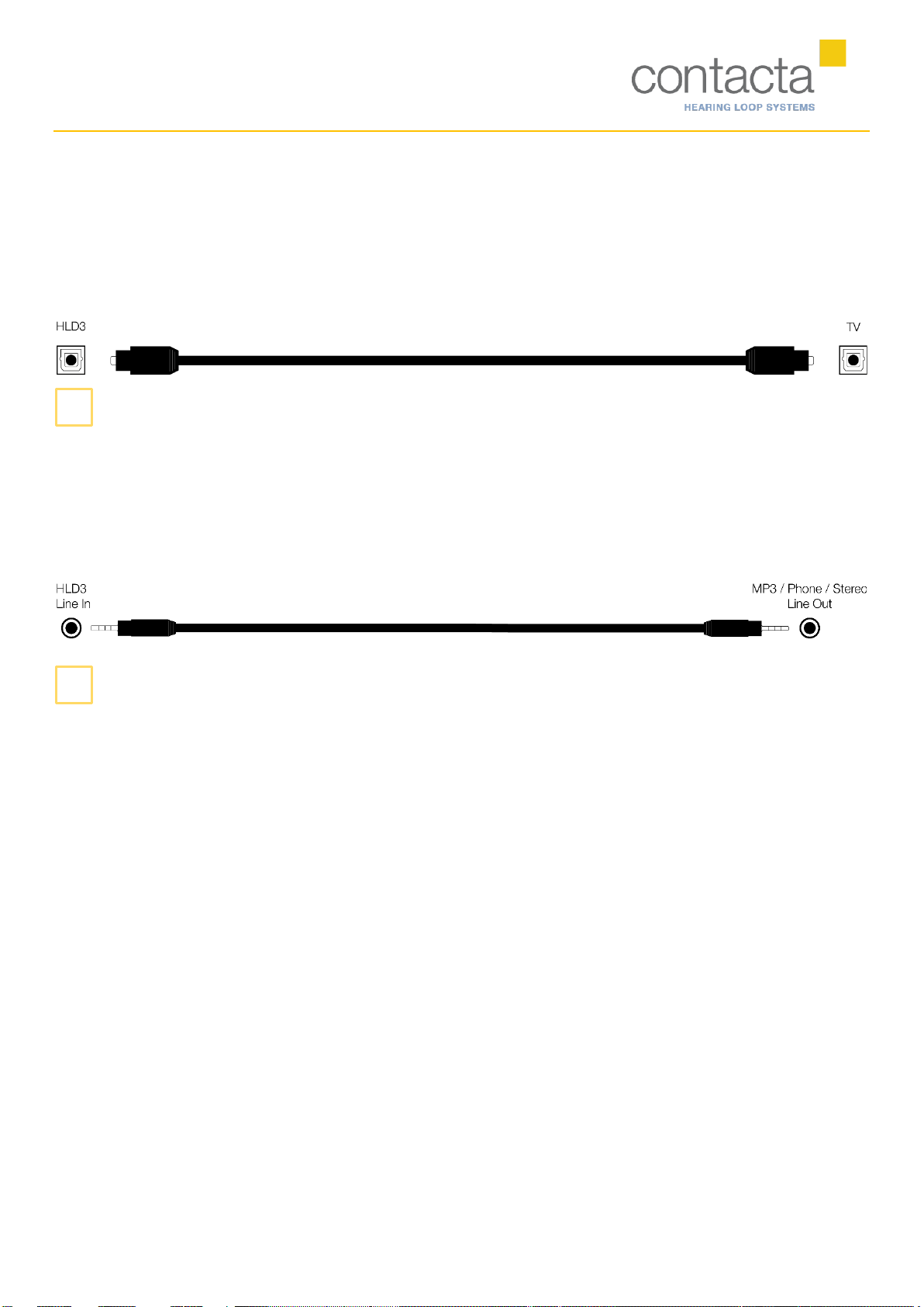
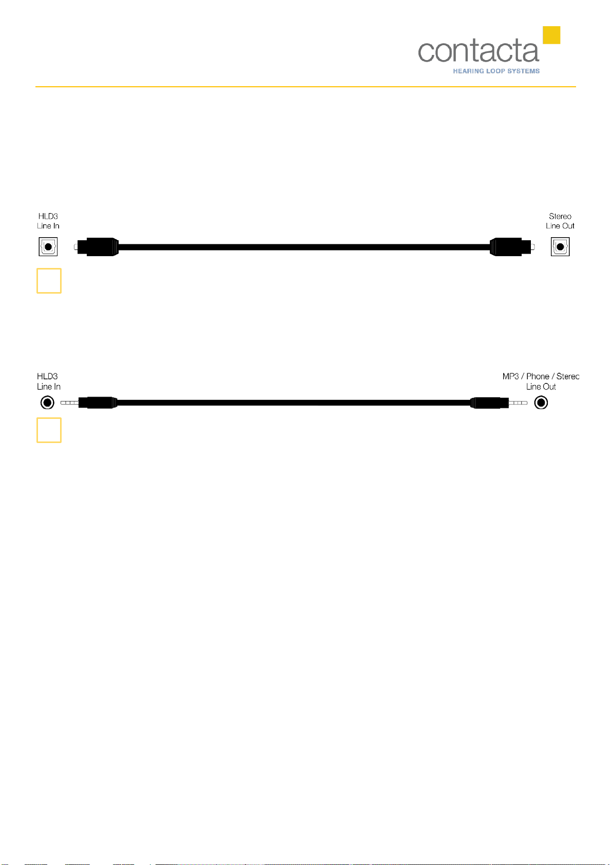
Auxiliary..................................................................................................................................................................... 7
Adjusting the HLD ........................................................................................................................................................... 8
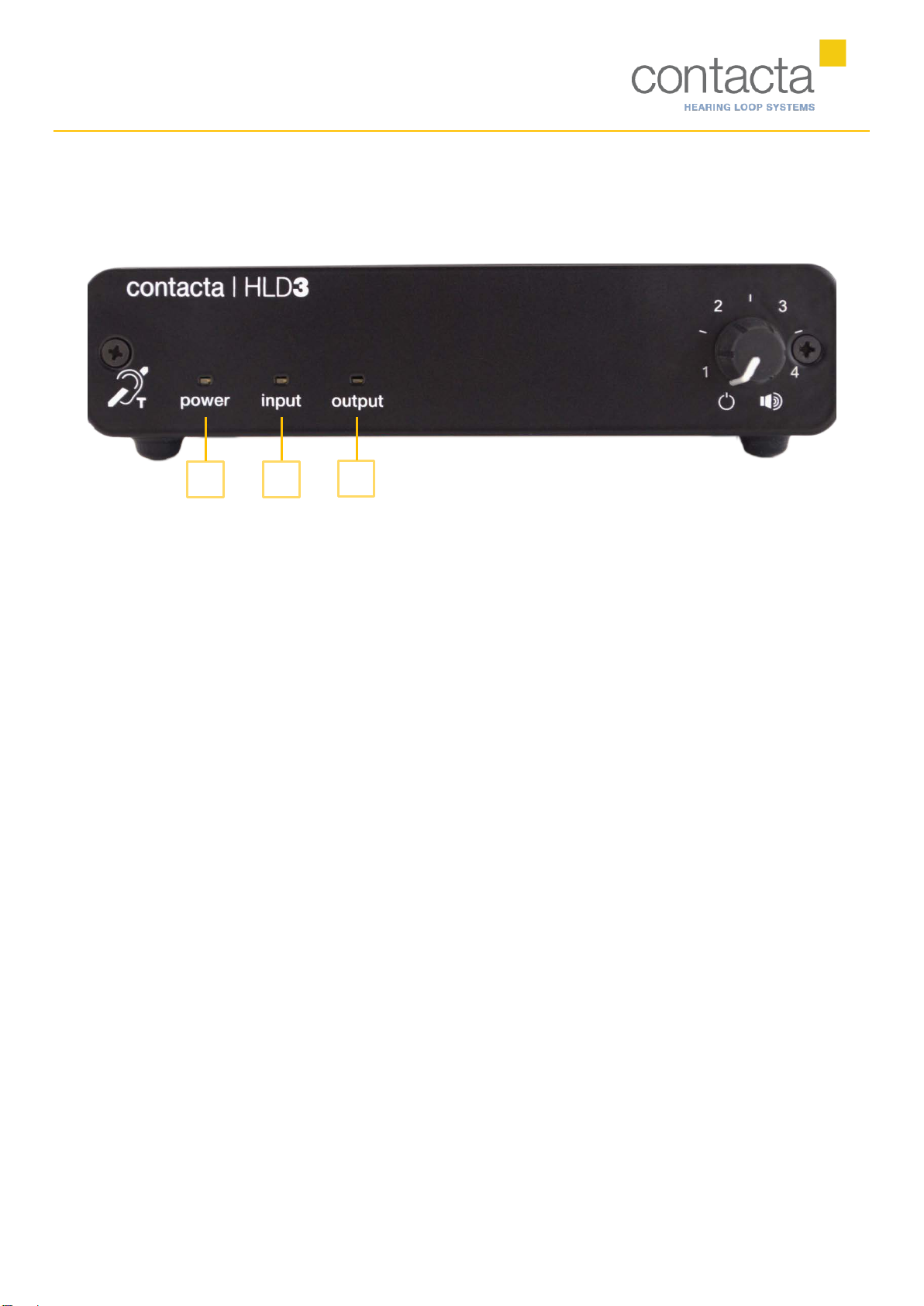
LED Indications................................................................................................................................................................ 9
Components
HLD3 Hearing Loop Driver (HLD)
Loop Pad
Loop Wire
Power Supply
Optical Cable
Auxiliary Cable
External microphone