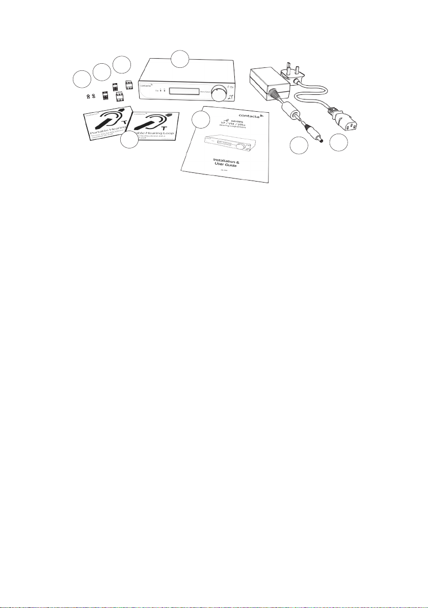
Contacta V15 Operation manual

1
V7 / V15 / V15a
Installation &
User Guide
November 2019
Hearing Loop Drivers

2
Contents
Product Overview
Components
Connections
Suitable Cable Lengths
Start-Up Tests
Controls
Hearing Loop Setup
Troubleshooting
Technical Specications
Standards
3
4-5
6-7
8-10
12
13-21
22-27
28
29-31
32
Contacta has a policy of continuous product development, therefore small specification
changes may not be reflected in this manual. Images, labels, packaging, accessories and
product colors are subject to change without notice.

3
Product Overview
Our highly eicient and compact V7, V15 and V15a hearing loop drivers
are suitable for smaller facilities and venues.
The V7 and V15 are constant current hearing loop drivers which power
hearing loops utilising a single output. The V15a is a constant current
dual output hearing loop driver with integral phase shifter for phased
array conguration.
These hearing loop drivers have Class-D amplier output stages and
an audio subsystem built around an advanced DSP core. Combined
with a powerful CPU that ensures peak performance, they use cutting
edge technology proven in the pro audio world to achieve life-like
speech and rst-class music reproduction.
Note: For large area hearing loop installation instructions, consult the
Large Area Hearing Loop Installation Guide.

4
Components
1. Rubber Feet x4
2. 0.508cm Euro-Block Connector
3. 0.381cm Euro-Block Connector x2
4. Signage
5. V7 Hearing Loop Driver
6. Installation & User Guide
7. Power Supply [PS-55]
8. IEC Power Lead*
V7
5
6
48
7
123
1. Rubber Feet x4
2. 0.508cm Euro-Block Connector
3. 0.381cm Euro-Block Connector x2
4. Signage
5. V15 Hearing Loop Driver
6. Installation & User Guide
7. Power Supply [PS-60]
8. IEC Power Lead*
V15
5
6
48
7
123
*Plug type varies by country.

5
*Plug type varies by country.
Cable & Equipment: A length of loop cable determined by the loop
design is also required. Hearing loop drivers also require ancillary
equipment for audio feeds, such as a microphone or sound system.
5
6
1. Rubber Feet x4
2. 0.508cm Euro-Block Connector x2
3. 0.381cm Euro-Block Connector x2
4. Signage
5. V15a Hearing Loop Driver
6. Installation & User Guide
7. Power Supply [PS-60]
8. IEC Power Lead*
48
7
V15a
123

6
1. Microphone Input - 3.81mm Euro-block balanced microphone
input (12V phantom power via 680Ω).
2. Line Input 1*- 3.81mm Euro-block balanced line input/feedthrough.
3. Line Input 2*- XLR balanced line input/feedthrough.
4. Power Supply Input - *V7 DC Power Input, 2.1mm 14Vdc 2.14A
***V15 DC Power Input, 2.1mm 24Vdc 4.17A
**V15a DC Power Input, 2.1mm 24Vdc 4.17A
Caution: Use only the provided Power Supply.
5. Loop A Output - 5.08mm Euro-block.
6. Loop B Output - 5.08mm Euro-block [V15a only].
Rear Panel Connections
Connections
1 2 3456
*Note: Only connect to one Line Input at a time.

7
Connection Examples
XLR to XLR (line)
TRS to XLR (line)
Unbalanced to XLR
XLR to Euroblock (balanced)
Unbalanced to Euroblock

8
Suitable Cable Lengths
The tables in this section show the approximate maximum cable
lengths for diering maximum required currents.
Loop impedance (at 1.6kHz) should be less than the voltage capability
of the driver (V7: 7.5Vrms, V15: 15Vrms, V15a: 15Vrms) divided by the
required current.
This achieves 400mA/m eld strength at 1kHz.
Current 2.0A 3.0A 4.0A 5.0A
Cable Type Cable Length
Maximum
Cable
Length
Round
Cable
(CSA)
0.5mm 85m 56m 42m 34m
1mm 133m 89m 66m 53m
1.5mm 155m 103m 77m 62m
2.5mm 173m 115m 86m 69m
Flat Cable
(Width)
10mm 101m 67m 50m 40m
12.5mm 192m 128m 96m 77m
25mm 255m 170m 127m 102m
V7 Single-Turn Hearing Loop (Metric)
V7 Single-Turn Hearing Loop (Imperial)
Current 2.0A 3.0A 4.0A 5.0A
Cable Type Cable Length
Maximum
Cable
Length
Round
Cable
(AWG)
18AWG 438ft 292ft 219ft 175ft
14AWG 593ft 395ft 296ft 237ft
Flat Cable
(Width)
18AWG
(equivalent)
505ft 336ft 252ft 202ft
14AWG
(equivalent)
711ft 474ft 355ft 284ft

9
Current 2.0A 3.0A 4.0A 5.0A
Cable Type Cable Length
Maximum
Cable
Length
Round
Cable
(CSA)
1mm 242m 161m 121m 97m
1.5mm 284m 189m 142m 114m
2.5mm 319m 213m 160m 128m
Flat Cable
(Width)
10mm 180m 120m 90m 72m
12.5mm 340m 226m 170m 136m
25mm 450m 300m 225m 180m
V15 Single-Turn Hearing Loop (Metric)
Current 2.0A 3.0A 4.0A 5.0A
Cable Type Cable Length
Maximum
Cable
Length
Round
Cable
(AWG)
18AWG 746ft 498ft 373ft 299ft
14AWG 997ft 664ft 498ft 399ft
Flat Cable
(Width)
18AWG
(equivalent)
840ft 560ft 420ft 336ft
14AWG
(equivalent)
1327ft 885ft 663ft 531ft
V15 Single-Turn Hearing Loop (Imperial)

10
Current 2.0A 3.0A 4.0A 5.0A
Cable Type Cable Length
Maximum
Cable
Length
Round
Cable
(CSA)
1mm 266m 177m 133m 106m
1.5mm 311m 208m 156m 125m
2.5mm 350m 233m 175m 140m
Flat Cable
(Width)
10mm 197m 131m 99m 79m
12.5mm 373m 249m 186m 149m
25mm 493m 329m 247m 197m
V15a Single-Turn Hearing Loop (Metric)
Current 2.0A 3.0A 4.0A 5.0A
Cable Type Cable Length
Maximum
Cable
Length
Round
Cable
(CSA)
1mm 193m 129m 97m 77m
1.5mm 209m 139m 104m 83m
2.5mm 219m 146m 110m 88m
Flat Cable
(Width)
10mm 172m 115m 86m 69m
12.5mm 267m 178m 133m 107m
25mm 316m 211m 158m 126m
V15a Double-Turn Hearing Loop (Metric)

11
Current 2.0A 3.0A 4.0A 5.0A
Cable Type Cable Length
Maximum
Cable
Length
Round
Cable
(AWG)
18AWG 819ft 546ft 409ft 328ft
14AWG 1093ft 729ft 547ft 437ft
Flat Cable
(Width)
18AWG
(equivalent)
921ft 614ft 461ft 369ft
14AWG
(equivalent)
1456ft 971ft 728ft 582ft
V15a Single-Turn Hearing Loop (Imperial)
Current 2.0A 3.0A 4.0A 5.0A
Cable Type Cable Length
Maximum
Cable
Length
Round
Cable
(AWG)
18AWG 598ft 399ft 299ft 239ft
14AWG 684ft 456ft 342ft 273ft
Flat Cable
(Width)
18AWG
(equivalent)
723ft 482ft 362ft 289ft
14AWG
(equivalent)
949ft 633ft 475ft 380ft
V15a Double-Turn Hearing Loop (Imperial)

12
Start-Up Tests
V Series drivers perform a series of tests when powered on, causing a
number of indications to appear on the display screen during start-up.
The meanings of these indications are as follows:
Indicator Meaning Remedy
V7 and V15:
Loop Good
V15a:
Loop A Good
Loop B Good
Hearing loop(s) is/are correctly
connected to the driver.
None required.
V7 and V15:
Loop Open Fault
V15a:
Loop A Open Fault
Loop B Open Fault
Hearing loop(s) is/are improperly
connected to the driver.
An open-circuit loop will not
damage the driver, and start-up
will continue to the main menu.
Ensure that the loop(s) is
properly connected to the
driver. The loop current
indication in normal
operation may be used to
conrm the connections.
V7 and V15:
Loop Ground Fault
V15a:
Loop A Ground Fault
Loop B Ground Fault
A ground fault with the hearing
loop(s) has been found.
The driver will halt operation
with this message displayed on
screen, as such a fault would
cause stress to the driver were
normal operation to continue.
Switch o the driver and
carefully check the loop(s) for
shorts to ground. Rectify the
faults and re-apply power to
the driver.
Incorrect Power The power input supply voltage
from the mains power supply is
incorrect.
The driver will halt operation
with this message displayed on
screen, as such a fault would
cause stress to the driver were it
to continue to normal operation.
Switch o the driver and
connect the power supply
which was provided with the
driver. If this is not available,
contact your distributor to
order a new power supply.
Please note if using V15a: If connecting only one loop to a V15a, whichever loop connection has
not been used (either Loop A or Loop B) will show as an “Open Fault” as default. This is the cor-
rect display for operation with only one loop; continue as normal.

13
Front Panel Overview
Controls
1. Clip Status Light - When lit, this status LED indicates the signal on
the hearing loop output is clipping (see Troubleshooting on page
28 for appropriate solutions).
2. Display Screen - Indicates the status of the Loop Output, displays
menu and adjustment options.
3. Control Dial - Used for unlocking and making adjustments.
V7 and V15
1. Clip Status Light - When lit, this status LED indicates the signal on
Hearing Loop A is clipping (see Troubleshooting on page 28 for
appropriate solutions).
2. Clip Status Light - When lit, this status LED indicates the signal on
Hearing Loop B is clipping (see Troubleshooting on page 28 for
appropriate solutions).
3. Display Screen - Indicates the status of the Loop Output, displays
menu and adjustment options.
4. Control Dial - Used for unlocking and making adjustments.
V15a
12
3
1 2
4
3

14
The hearing loop driver will power up in Output Current Display Mode
and will be locked from entering Adjustment Mode.
Unlock the Driver
1. To unlock the hearing loop driver, press the control dial, and when
prompted “Unlock driver?” click “Yes.”
2. Enter the passcode 2239:
a. Rotate the control clockwise to select the rst required digit.
b. Press the control dial in to select the digit.
c. Repeat steps (a) and (b) until all the digits have been selected.
Note: Entering the wrong code returns the hearing loop driver to the
lock screen.
Additional Functions and Codes
1. To access one of the additional functions available, press the
control dial, and when prompted “Unlock driver?” click “Yes.”
2. Enter one of the following passcodes:
• 1010: Disable the display backlight 10 minute auto switch-o.
This setting is remembered through power cycles.
• 1011: Enable the display backlight 10 minute auto switch-o.
This setting is remembered through power cycles.
• 9999: Disable the auto re-lock (timeout). This is not
remembered through power cycles.
• 8888: Restore all factory defaults and restart the driver.
Locking/Unlocking the Hearing Loop Driver

15
Modes
Main Menu
After being unlocked, the hearing loop driver will display the main
menu. This is indicated by up and down arrows on the display screen.
V7 and V15
1. Loop Output
2. Line Input
3. Phantom Power
4. Microphone Input
5. Current Output (no adjustment)
6. High-Frequency Compensation
V15a
1. Loop Output
2. Line Input
3. Phantom Power
4. Microphone Input
5. Loop B Trim Adjustment
6. High-Frequency Compensation
When in this mode, rotating the hearing loop driver’s control dial
clockwise will move the screen to the next menu item and rotating the
dial anti-clockwise will move it to the previous menu item.
The menu options are as follows:
Adjustment Mode
Press the control dial in to enter Adjustment Mode; the arrows on the
display screen will move to a left and right position.
Rotate the dial clockwise or anti-clockwise to make the adjustment.
Press the control dial in to conrm the selection and return to the main
menu.
If the control dial is not used for 120 seconds when in Adjustment
Mode the hearing loop driver will revert to the main menu, with Loop
Output as the default screen.

16
V7 and V15 Loop Output V15a Loop Output
V7 and V15 Loop Output: Adjustment Mode V15a Loop Output: Adjustment Mode
Adjustments
Loop Output
In Adjustment Mode, the real-time output current is displayed on the
top line in 0.5A steps. The bottom line indicates the strength of the
loop output level adjustment.
To alter the loop output level, enter Adjustment Mode:
•To increase the loop output level, rotate the control dial clockwise.
• To decrease the loop output level, rotate the control dial
anti-clockwise.
•Press the control dial once to conrm the selection and return to
the main menu.
The hearing loop driver’s Loop Output section displays the real-time
output current in 0.5A steps.

17
Adjustments
It is recommended that at least 5 blocks in the adjustment block are
lled (see the above image for an example).
Enter Adjustment Mode, and alter the line input level displayed on the
bar until the text displays ‘Good’:
•To increase the line input level, rotate the control dial clockwise.
• To decrease the line input level, rotate the control dial
anti-clockwise.
•Press the control dial once to conrm the selection and return to
the main menu.
Line Input
The hearing loop driver’s Line Input section displays the line input
level within a range of 47dB.
The text on the display indicates if the correct line level has been
achieved:
•“Low” indicates the line level is too low for the automatic gain
control to operate.
•“Good” indicates the line level is at an optimum level for the
automatic gain control to operate.
•“High” indicates the line level is too high and signal clipping may
occur. Signal clipping will also be shown by the LED.

18
Adjustments
Phantom Power
Rotating the control dial clockwise or anti-clockwise in Adjustment
Mode will toggle the phantom power on or o. Press the control dial
once to conrm the selection and return to the main menu.
Phantom power for a connected microphone is set o as the default
setting.

19
It is recommended that at least 5 blocks in the adjustment block are
lled (see the above image for an example).
Enter Adjustment Mode and alter the microphone input level
displayed on the bar until the text displays ‘Good’:
• To increase the microphone input level, rotate the control dial
clockwise.
• To decrease the microphone input level, rotate the control dial
anti-clockwise.
•Press the control dial once to conrm the selection and return to
the main menu.
The hearing loop driver’s Microphone Input section displays the
microphone input level within a range of 47dB.
The top line of the display indicates if the correct microphone input
level has been achieved:
•“Low” indicates the microphone level is too low for the automatic
gain control to operate.
•“Good” indicates the microphone level is at an optimum level for
the automatic gain control to operate.
•“High” indicates the microphone level is too high and signal
clipping may occur. Signal clipping will also be shown by the LED.
Adjustments
Microphone Input

20
V15a Only: Loop Trim
When using a V15a, the hearing loop driver’s Loop Trim function
allows Loop B’s output to be adjusted relative to Loop A’s output.
Please note: This section is only available on the V15a. The equivalent
V7 and V15 menu displays Current Output, to which adjustments can
be made using the Loop Output section (see page 16).
-
When in the Loop Trim section, adjustments are made in 1dB steps.
The measured loop output current is displayed in amps RMS (accurate
for sine signals).
Adjustments
Enter Adjustment Mode to alter “Loop B Trim” relative to “Loop A”.
•To increase the Loop B Trim level, rotate the control dial clockwise.
•To decrease the Loop B Trim level, rotate the control dial
anti-clockwise.
•Press the control dial once to conrm the selection and return to
the main menu.
This manual suits for next models
3
Table of contents
Other Contacta Amplifier manuals