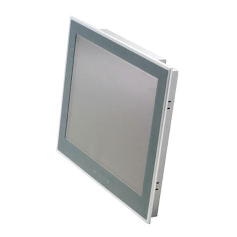
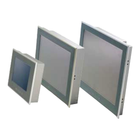
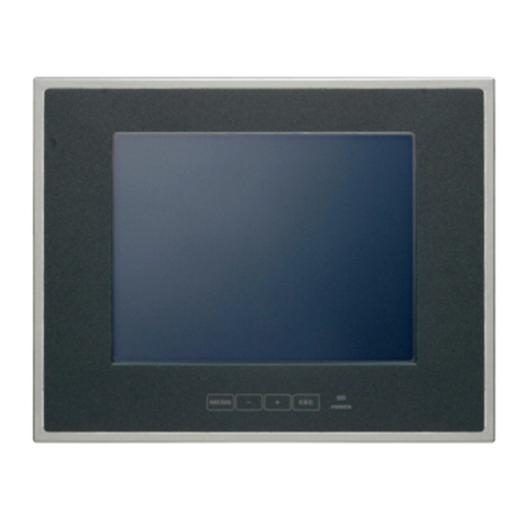
Contec IPC-DT User manual

IPC Series
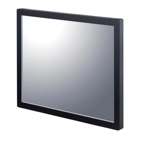
Analogue RGB input flat panel display
10.4inch
IPC-DT/M20V(PC)T
12.1inch
IPC-DT/L20S(PC)T
15inch
IPC-DT/H20X(PC)T
User's Manual
CONTEC CO.,LTD.

User’s Manual i
Copyright
Copyright 2002 CONTEC CO., LTD. ALL RIGHTS RESERVED
No part of this document may be copied or reproduced in any form
by any means without prior written consent of CONTEC CO., LTD.
CONTEC CO., LTD. makes no commitment to update or keep
current the information contained in this document.
The information in this document is subject to change without
notice.
All relevant issues have been considered in the preparation of this
document. Should you notice an omission or any questionable
item in this document, please feel free to notify
CONTEC CO., LTD.
Regardless of the foregoing statement, CONTEC assumes no
responsibility for any errors that may appear in this document nor
for results obtained by the user as a result of using this product.
Trademarks
MS, Microsoft, MS-DOS and Windows are trademarks of Microsoft
Corporation. Other brand and product names are trademarks of their
respective holder.
FCC PART 15 Class A Notice
This equipment has been tested and found to comply with the limits for a ClassAdigital device,
pursuant to part 15 of the FCC Rules. These limits are designed to provide reasonable protection
against harmful interference when the equipment is operated in commercial environment.
This equipment generates, uses, and can radiate radio frequency energy and, if not installed and
used in accordance with the instruction manual, may cause harmful interference to radio
communications. Operation of this equipment in a residential area is likely to cause harmful
interference at his own expense.
NOTE
Change or modifications not expressly approved the manufacturer can void the user's authority to
operate this equipment.
WARNING TO USER
Note!
To connect with peripherals, use a grounded, shielded cable.

ii User’s Manual
Table of Contents
Copyright........................................................................... i
Trademarks........................................................................ i
FCC PART 15 Class A Notice ....................................... i
Table of Contents..............................................................ii
1.Introduction.......................................................................1
Features........................................................................ 1
Limited One-Year Warranty........................................ 2
How to Obtain Service................................................. 2
Liability ........................................................................ 2
Handling Precautions.................................................. 3
2.Specifications.....................................................................7
Function Specifications.................................................... 7
General Specifications ..................................................... 9
Optical Display Specifications....................................... 10
3.Outside Dimensions and Part Names ............................11
Outside Dimensions........................................................11
Part Names..................................................................... 14
Analog RGB Connector.............................................. 15
RS Touch Panel Connector ........................................ 15
USB Touch Panel Connector ..................................... 16
Dip Switch.................................................................. 17
Backlight ON/OFF Connector................................... 18
4.Setting the Display .........................................................19
Installation Requirements......................................... 19
Panel Cut........................................................................ 20
Attaching the Fitting Used to Attach to
the Main Unit............................................................. 22
5.Connection to the Host Computer..................................25
Analog RGB Connection ................................................ 25
Touch Panel Data Communications.............................. 26

User’s Manual iii
6.Power Supply Connection ..............................................27
Power Supply Connector................................................27
AC Adapter Jack.............................................................28
AC code removal prevention fitting...........................29
7.Screen Adjustment and a Setup..................................... 31
Menu Screen...................................................................31
Direct Key.......................................................................36
Memory of a Setting Value.............................................36
8.LED Indicators ............................................................... 37
9.Touch Panel..................................................................... 39
USB Multi-Touch Panel .................................................41
10.Display Mode................................................................ 43
11.Options.......................................................................... 45

iv User’s Manual

1. Introduction
User’s Manual 1
1. Introduction
This equipment is an analog RGB signal input, color TFT LCD for
use in combination with a host computer such as the CONTEC IPC
Series or single-board computer (SBC).
Features
- Full-bright, wide-angle-of-visibility type of liquid crystals capable
of displaying up to 16,777,216 colors(15inch), 262,144
colors(10inch / 12.1inch)
- Standard analog RGB input for screen. RS-232C and USB
interfaces for touch panel.
- Multiple touch panel configurations containing up to eight touch
panels are supported when using the USB touch panel interface.
- Auto-scaling feature that resizes the input screen to the LCD dot
configuration.
- On-screen display setup menu facilitating screen adjustment
- Analog touch panel enabling mouse emulation using driver
software
- Input connector allowing external control of turning on/off the
backlight
- Back-mounted, dedicated power supply unit [IPC-POA200/12-01]
and AC adapter [IPC-ACAP12-01] available as an option,
enabling the LCD to be used with an AC power supply
- Front structure with IP65-compliant ingress protection
- Optional stand kit for tabletop use
* For the host computer to be used with the display or its options,
contact your local CONTEC branch or sales office.

1. Introduction
2User’s Manual
Limited One-Year Warranty
CONTEC Interface boards are warranted by CONTEC CO., LTD.
to be free from defects in material and workmanship for up to one
year from the date of purchase by the original purchaser.
Repair will be free of charge only when this device is returned
freight prepaid with a copy of the original invoice and a Return
Merchandise Authorization to the distributor or the CONTEC group
office, from which it was purchased.
This warranty is not applicable for scratches or normal wear, but
only for the electronic circuitry and original boards. The warranty
is not applicable if the device has been tampered with or damaged
through abuse, mistreatment, neglect, or unreasonable use, or if the
original invoice is not included, in which case repairs will be
considered beyond the warranty policy.
How to Obtain Service
For replacement or repair, return the device freight prepaid, with a
copy of the original invoice. Please obtain a Return Merchandise
Authorization Number (RMA) from the CONTEC group office
where you purchased before returning any product.
* No product will be accepted by CONTEC group without the
RMA number.
Liability
The obligation of the warrantor is solely to repair or replace the product.
In no event will the warrantor be liable for any incidental or
consequential damages due to such defect or consequences that arise
from inexperienced usage, misuse, or malfunction of this device.

1. Introduction
User’s Manual 3
Handling Precautions
Take the following precautions when handling this board.
- This display is made of the precise electric parts, so do not use or
store it in the vicinity of impulse or vibration.
- This product is not intended for use in aerospace, space, nuclear
power, medical equipment, or other applications that require a
very high level of reliability. Do not use the product in such
applications.
- If you utilize this product in such usages where high reliability
and safety are required as on the trains, vessels, automotives or
crime- or disaster-prevention devices, contact your retailer.
- Do not use or store the product in a location exposed to extremely
high or low temperature or susceptible to rapid temperature
changes.
Example: - Exposure to direct sun
- In the vicinity of a heat source
- Do not use the product in extremely humid or dusty locations.
- Do not perform key operations with the touch panel to implement
a process that might endanger life or result in serious damages.
Design a system that can cope with incorrect key input operations.
- Do not use a sharp-edged object, such as a mechanical pencil, to
operate the touch panel in order to prevent scratching or
malfunctions.
- Protect the touch panel against shock to prevent damage.
- CONTEC is not liable for a product that has been modified by the
user.
- For this equipment, use the dedicated power supply unit if
possible. If you connect any other power supply unit, be sure to
select the one that satisfies the voltage and current capacity
standards.
- Never supply power to the power supply connector and the AC
adapter jack at the same time as it can cause a fault.
- When the surface or frame of the touch panel has become dirty,
wipe it with neutral detergent. Do not wipe the touch panel with
thinner, alcohol, ammonia, or a strong chlorinated solvent.
1. Introduction
4User’s Manual
- Do not plug or unplug the connector with the equipment powered
on. As doing so may result in a malfunction or fault.
- In the event of failure or abnormality, contact your retailer.
Use environment
This product operates under the following operating systems:
Windows XP/2000/NT 4.0/98SE/95OSR2, MS-DOS 6.2
* The touch panel USB interface is only supported on Windows
XP/2000/98SE.
Life expectancy of components
(1) Backlight--- Display brightness decreases over time with use.
The operating lifetime of the backlight is as
follows. (The time until the brightness is lowered
to 50% of the initial value. , Assuming
continuous operation at 25 degrees centigrade.)
- IPC-DT/M20V(PC)T : 50,000 hours
- IPC-DT/L20S(PC)T : 50,000 hours
- IPC-DT/H20X(PC)T : 25,000 hours
(2) Touch panel--- The operating lifetime of the touch panel is at
least 1 million touches (as tested by mechanical
touching under 300g of force at a rate of two
presses per second).
* CONTEC accepts your request for replacing each consumable in
the PANECON-PC as a request for repair (at an additional cost).
Contact your local retailer or CONTEC sales office.
LCD Display Pixel Drop
LCD display may have some pixels being dropped (bright and
black spots) below a certain threshold. Note that this is not a
failure or a defect.
Burn-in on TFT Display
"Burn-in" may occur if the same display is retained for a long
time. Avoid this by periodically switching the display so that
the same display is not maintained for a long time.
* Burn-In: Phenomenon characterized by a TFT display as a
result of long-time display of the same screen where a shadow-
like trace persists because electric charge remains in the LCD
element even after the patterns are changed.

1. Introduction
User’s Manual 5
Connecting to a host with an existing touch panel function such
as a CONTEC panel computer.
The touch panel cannot be used together with the built-in touch
panel on the computer. In this case, the touch panel on the
screen cannot be used (although display operation is still
available.)
However, on the following CONTEC panel computers, multiple
touch panels can be used together when connected via the USB
interface.
- IPC-PT/600 Series IPC-PT/x6x0x(PCW)x

1. Introduction
6User’s Manual

2. Specifications
User’s Manual 7
2. Specifications
Function Specifications
Table 2.1. Function Specifications < 1 / 2 >
Specification
Item IPC-DT/M20V(PC)T IPC-DT/L20S(PC)T IPC-DT/H20X(PC)T
Screen
Assembly type Panel mounted *1
Screen size 10.4 inches 12.1 inches 15 inches
Number of pixels 640 x 480 dots 800 x 600 dots 1024 x 768 dots
Display type TFT Color LCD
Number of colors 262,144 colors 262,144 colors 16,777,216 colors
Screen adjustment Automatic adjustment (display positioning and scaling) and manual adjustment
using the front switches
Brightness control Adjustment using the front switch or software control from the host computer
Backlight control Adjustment using the front switch, software control from the host computer, or
ON/OFF control via the rear-panel connector input
Display interface Analog RGB input HD-SUB 15 pin (Female) connector
Cable length which recommends 5mm or less *2
Picture signal RGB separation, Analog, Positive polarity 0.7Vp-p/75Ω
Synchronized
signal V/H separation, TTL, Positive / negative polarity
Horizontal scan
frequency 31 - 38kHz 31 - 48kHz 31 - 60kHz
Incoming signal
specification
Vertical scan
frequency 60 - 72Hz 56 - 72Hz 56 - 75Hz
Touch panel
Resolution 4096 x 4096
Detection method Resistive-layer analog method
Touch life expectancy One million repeated touches (silicon rubber load of 3 N)
Touch panel interface Connect to the host computer using either USB*3 or RS-232C.
USB: USB1.1-compliant, TypeB Connector
RS-232C: 9pin D-SUB (Male) Connector
Touch panel driver
(Option) Windows : IPC-SLIB-01
MS-DOS : IPC-TPB1-DRV

2. Specifications
8User’s Manual
Table 2.1. Function Specifications < 2 / 2 >
Specification
Item IPC-DT/M20V(PC)T IPC-DT/L20S(PC)T IPC-DT/H20X(PC)T
Power supply input part
Power supply connector 4-pin nylon connector for 12 VDC power supply
(Back-mounted, power supply unit [IPC-POA200/12-01] available as an option,
enabling input at 85 - 264 VAC)
AC adapter jack AC adapter jack for 12 VDC power supply
(Power supply unit [IPC-ACAP12-01] available as an option, enabling input
at 100 - 240 VAC)
Input power supply voltage DC+12V±5%
Power consumption 1.3A(Max.) 1.6A(Max.) 1.8A(Max.)
Power consumption
(power save mode) 0.2A(Max.)
*1 Optional desk stand IPC-SND-03 allowing desktop installation.
*2 Using a cable longer than 5 m may reduce the image quality. The cable should be as short as possible as degradation
in image quality may result even when the cable is 5 m or shorter depending on the type of host computer or cable.
*3 The touch panel USB interface is only supported on Windows XP/2000/98SE.

2. Specifications
User’s Manual 9
General Specifications
Table 2.2. General Specifications
Specification
Condition IPC-DT/M20V(PC)T IPC-DT/L20S(PC)T IPC-DT/H20X(PC)T
Environment
Operating temperature 0 - 50ºC (0 - 40ºC when using an IPC-ACAP12-01 (AC switching adapter))
Storage temperature -10 - 60ºC
Operating humidity 10 - 90%RH
(20 - 80% when using an IPC-ACAP12-01 (AC switching adapter))
(No condensation allowed)
Floating dust Normal
Corrosive gas None
Line noise AC line: 2 kV, Signal line: 1 kV
(IEC1000-4-4Level3, EN61000-4-4Level3)
(HOST: IPC-BX/M600(PCW) Power supply: IPC-POA200/12-01)
Noise
resistance
Electrostatic
withstanding
voltages
Contact: 4 kV(IEC1000-4-2Level2, EN61000-4-2Level2)
Airborne: 8 kV(IEC1000-4-2Level3, EN61000-4-2Level3)
(HOST: IPC-BX/M600(PCW) Power supply: IPC-POA200/12-01)
Sweep
durability 10 - 50 Hz/Single-side amplitude or 0.15 mm
50 - 500 Hz/2.0 G in the X/Y/Z directions for 23 minutes each
(Conforming to JIS C0040 and IEC68-2-6)
Vibration
resistance
Fixed-vibration
durability 16.7 Hz/2 G in the X/Y/Z directions for 30 minutes each
(Conforming to JIS C0040 and IEC68-2-6)
Shock resistance 10 G in the X/Y/Z directions for 11 ms; Half-sine wave
(Conforming to JIS C0041 and IEC68-2-27)
Structure
Major dimensions (mm) 317(W) x 44(D) x 277(H) 370(W) x 48(D) x 307(H) 428(W) x 48(D) x 336(H)
Panel cut dimensions (mm) 292±0.5(W) x 252±0.5(H) 344±0.5(W) x 281±0.5(H)
(12 stud holes are required
on the periphery.)
398±0.5(W) x 306±0.5(H)
(12 stud holes are required
on the periphery.)
Mountable panel thickness 10 mm or less
Weight 3.5kg 4.4kg 5.5kg
Ingress protection Front part conforming to IP65

2. Specifications
10 User’s Manual
Optical Display Specifications
Table 2.3. Optical Display Specifications
Specifications (25ºC Typ. value)
Item Condition IPC-DT/M20V(PC)T IPC-DT/L20S(PC)T IPC-DT/H20X(PC)T
φ= 180° 40deg 50deg 45deg
Visual angle
(vertical) φ= 0° 70deg 70deg 55deg
φ= +90° 70deg 70deg 60deg
Visual angle
(horizontal)
CR≥10
φ= -90°
Display in
monochrome
70deg 70deg 60deg
Surface brightness
(at center) Display in white 350cd/m2 (Typ.) 350cd/m2 (Typ.) 250cd/m2
Left
( φ=
-
90o )
Z
Y
X
Top
( φ= 180o )
Right
( φ= 90o )
Bottom
( φ = 0o )
( θ= 0o )
Measurement direction
θ
Module
φ
Figure 2.1. Viewing Range Definition
Note! The above optical specification data shows optical characteristics of
the liquid crystal in the display; the data does not represent the
actual view on the display or its viewing angles

3. Outside Dimensions and Part Names
User’s Manual 11
3. Outside Dimensions and Part Names
Outside Dimensions
IPC-DT/M20V(PC)T
37
[mm]
317
230
291
145 (95.5)
277
250
100
7
234
100
(18.5)
2.444
37
4-M4 TAP(Including the mate)
(Maximum tapping length:4mm)
4-M4 TAP(Including the mate)
(Maximum tapping length:4mm)
4-M4 TAP
(Maximum tapping length:4mm) 115
105.5
Figure 3.1. Outside Dimensions of Main Unit
(IPC-DT/M20V(PC)T)
IPC-DT/L20S(PC)T
266 4-M4 TAP(Including the mate)
Maximum tapping length:4mm)
4-M4 TAP(Including the mate)
(Maximum tapping length:4mm)
4-M4 TAP
(Maximum tapping length:4mm)
370
342
119119 119
(69.7)
100
307
279
98 9898
100
(22.3)
15.5
254
5
189.5
251
137.5
122.5
[mm]
12-M4 STUD
48
13
2.4
Figure 3.2. Outside Dimensions of Main Unit
(IPC-DT/L20S(PC)T)

3. Outside Dimensions and Part Names
12 User’s Manual
IPC-DT/H20X(PC)T
[mm]
302 4-M4 TAP(Including the mate)
(Maximum tapping length:4mm)
4-M4 TAP(Including the mate)
(Maximum tapping length:4mm)
4-M4 TAP
(Maximum tapping length:4mm)
15.5
12-M4 STUD
48
13
2.4
336
106
304
106 107
100
100
428
396
137 137 137
(96.7) (22.3)
15.5
254
7233.1
309.1
157.5
138
Figure 3.3. Outside Dimensions of Main Unit
(IPC-DT/H20X(PC)T)
IPC-DT/M20V(PC)T with IPC-POA200/12-01
(power supply unit)
2.4 54
44
(1.5) [mm]
Figure 3.4. Dimensions of IPC-DT/M20V(PC)T with
IPC-POA200/12-01

3. Outside Dimensions and Part Names
User’s Manual 13
IPC-DT/L20S(PC)T with IPC-POA200/12-01
(power supply unit)
2.4 58
48
(0.8) [mm]
Figure 3.5. Dimensions of IPC-DT/L20S(PC)T with
IPC-POA200/12-01
IPC-DT/H20X(PC)T with IPC-POA200/12-01
(power supply unit)
2.4 58
48
[mm]
Figure 3.6. Dimensions of IPC-DT/H20X(PC)T with
IPC-POA200/12-01

3. Outside Dimensions and Part Names
14 User’s Manual
Part Names
Front
BackRight side Left side
Screen & Touch panel
Power LED
Screen adjustment switch
Power supply connector
AC adapter jack
Dip switch
Analog RGB connector
RS touch panel connector
Backlight ON/OFF connector
USB touch panel connector
Figure 3.7. Part Names
Figure 3.8. Screen Adjustment Switch

3. Outside Dimensions and Part Names
User’s Manual 15
Analog RGB Connector
Table 3.1. Analog RGB Connector
Connector type
Pin No.
1
2
3
4
5
6
7
8
Pin No.
9
10
11
12
13
14
15
Signal name
RED
GREEN
BLUE
N.C.
GND
R-GND
G-GND
B-GND
Signal name
N.C.
GND
N.C.
DDC DATA
HSYNC
VSYNC
DDC CLK
HD-SUB 15pin (FEMALE)
51
11
15
10 6
RS Touch Panel Connector
This connector is RS-232C compliant to be used for touch panel
data communication with the host computer.
Table 3.2. RS Touch Panel Connector
Connector type
Pin No.
1
2
3
4
5
Pin No.
6
7
8
9
Signal name
N.C.
TxD
RxD
Reserved
GND
Signal name
Reserved
N.C.
N.C.
N.C.
D-SUB 9pin (MALE)
1 5
9
6
This manual suits for next models
12
Table of contents
Other Contec Monitor manuals

Contec
Contec IPC-DT/L40S(PC)T User manual

Contec
Contec FPD-S71VT-DC1 User manual

Contec
Contec IPC-DT 61 User manual

Contec
Contec GPD-U64EM-DC2 User manual

Contec
Contec FPD-H21XT-AC User manual

Contec
Contec S71VT-DC1 User manual

Contec
Contec IPC SERIES User manual

Contec
Contec IPC SERIES User manual

Contec
Contec IPC-DT/L440(PC)TA User manual

Contec
Contec PM10 User manual