01 Keyboard & PS/2 Mouse (KBM1)
Type: Standard Mini-Din connector
02 Keyboard & PS/2 Mouse (KBM2)
Type: 6-pin wafer connector
Pin Description Pin Description
1 KB_DATA 2 GND
3 MS_DATA 4 KB_CLK
5 VCC 6 MS_CLK
03 ATX Power Connector (ATXP1)
04 05 DIMM1, DIMM2
06 12 CPU/System Fan Connector (CPUF1/SYSF1)
Type: Onboard 3-pin wafer connector
Pin Description
1 GND
2 +12V
3 Fan_Detect
07 08 Serial ATA(SATA1/SATA2)
High speed transfer rates (150MB/sec)
Type: Standard 7-pin SATA connector
Pin Description
1 GND
2 TX+
3 TX-
4 GND
5 RX+
6 RX-
7 GND
09 CMOS Setup (JBAT1)
Type: Onboard 3-pin header
CMOS Setup JBAT1
Keep CMOS 1-2 ON
Clear CMOS 2-3 ON
Default setting: 1-2
10 IDE Connector (IDE1)
Type: Standard 2.54mm 40-pin box header
11 Digital I/O Connector (DIO1)
Type: Onboard 2.54mm 2*5-pin header
Pin Description Pin Description
1 DIO1 2 DIO2
3 DIO3 4 DIO4
5 DIO5 6 DIO6
7 DIO7 8 DIO8
9 +5V 10 GND
13 Front Side BUS Clock Select (JFSB1)
Type: onboard 1*3-pin header
JFSB1 1-2 2-3
Front side bus 400MHz 533MHz
Default setting: 400MHz
14 PCI ExpressX16 Interface Slot (PCIE1)
15 Mini PCI Interface (MINIPCI1)
16 Switches and Indicators (JFRT1)
Type: Onboard 16-pin header
Pin Description Pin Description
1 Power LED+ 2 PWRBTN+
3 GND 4 PWRBTN-
5 GND 6 RESET+
7 HDD LED+ 8 RESET-
9 HDD LED- 10 SPEAKER+
11 SMBCLK 12 SPEAKER+
13 SMBDATA 14 SPEAKER-
15 GND 16 SPEAKER-
17 COM1 Power Source Special Support (JV1)
Type: onboard 1*3-pin header
COM1 Power SourceSupport JV1
Standard 2-3
POS: 5V on Pin1 1-2
Default setting: Standard
18 RS-422/485 Output Connector (CON1)
Type: Onboard 2.0mm 4-pin wafer connector
Pin RS-422 RS-485
1 TX+ DATA+
2 TX- DATA-
3 RX+ N.C
4 RX- N.C
RS-422/RS-485 Select by JRS1, share COM2
resource.
19 Serial Port Selection (RS232C/422/485) (JRS1)
The onboard COM2 port can be configured to operate
in RS-422 mode or in different RS-422/485 modes.
Mode Selection 1-2 3-4 5-6
RS-232 ON OFF OFF
RS-422 OFF ON OFF
RS-485 OFF OFF ON
Default setting: RS-232
20 21 USB Connector (USB1/USB2)
Type: Onboard 2.54mm 10-pin header for two USB
ports
Pin Description Pin Description
1 +5V 2 +5V
3 USBD- 4 USBD-
5 USBD+ 6 USBD+
7 GND 8 GND
9 GND 10 N.C
22 Parallel Port Connector (LPT1)
Type: Onboard 2.0mm 2*13-pin box header
Pin Description Pin Description
1 STROBE 14 AFD
2 PTD0 15 ERROR
3 PTD1 16 INIT
4 PTD2 17 SLIN
5 PTD3 18 GND
6 PTD4 19 GND
7 PTD5 20 GND
8 PTD6 21 GND
9 PTD7 22 GND
10 ACK 23 GND
11 BUSY 24 GND
12 PE 25 GND
13 SELECT 26 Key(N/C)
LPT1: Floppy Drive Connector
LPT1 can be configured as a connector of floppy disk
drive interface through BIOS setup
Type: Onboard 2.0mm 2*13-pin box header
Pin Description Pin Description
1 NC 14 RWC-
2 RINDEX- 15 HEAD-
3 TRAK0- 16 DIR-
4 WP- 17 STEP-
5 RDATA- 18 GND
6 DSKCHG- 19 GND
7 NC 20 GND
8 NC 21 GND
9 NC 22 GND
10 DSB- 23 GND
11 MOB- 24 GND
12 WD- 25 GND
13 WE- 26 Key(N/C)
5 6
78
31 LVDS LCD Connector (LVDS1)
Type: Onboard DF-13-30DP-1.25V
Pin Description Pin Description
1 VDD 2 VDD
3 TX1CLK+ 4 TX2CLK+
5 TX1CLK- 6 TX2CLK-
7 GND 8 GND
9 TX1D0+ 10 TX2D0+
11 TX1D0- 12 TX2D0-
13 GND 14 GND
15 TX1D1+ 16 TX2D1+
17 TX1D1- 18 TX2D1-
19 GND 20 GND
21 TX1D2+ 22 TX2D2+
23 TX1D2- 24 TX2D2-
25 GND 26 GND
27 NC 28 NC
29 NC 30 NC
VDDcould be selected by JVLCD1 in +5V or +3.3V.
32 CRT/DVI Connector (VGA1)
Note: Driver Install
CHIPSET: \DRIVER\CHIPSET\Intel\INF 7.2
IDE: \DRIVER\IDE\Intel\ICH7
VGA: \DRIVER\Graphics\Intel\9X5
USB: \DRIVER\USB2\ICH5
LAN: \DRIVER\Ethernet\Realtek
MONITOR: \DRIVER\H-MONITOR\Winbond
AUDIO: \DRIVER\AUDIO\Realtek
23 Infrared Connector (IR1)
Type : onboard 2.54mm 5-pin header
Pin Description
1 +5v
2NC
3 IRRX
4 GND
5 IRTX
24 Audio Interface Port (AUDIO1)
AC’97 Audio
25 RS-232 Serial Port (COM1)
Type: Two D-SUB 9 connecotor
26 27 USB/LAN Connector (LAN1/LAN2)
This connector supports USB 2.0 x 4 (USB 0, 1, 2,
3) & Gigabit RJ-45 Ethernet Connector.
28 AT/ATX Power Mode Select (JPWR1)
Type: Onboard 1*2-pin header
JPWR1 Select 1-2
AT-MODE SHORT
ATX-MODE OPEN
Default setting: ATX MODE
29 LCD Voltage Selection (JVLCD1)
Type: Onboard 3-pin header
The voltage of LCD panel could be selected by
JVLCD1 in 5V or 3.3V.
Mode JVLCD1
3.3V 2-3
5V 1-2
Default setting: 3.3V
30 LCD Inverter Connector (INV1)
Type: Onboard 5-pin wafer connector
Pin Description Pin Description
1 +12 V 2 GND
3 Backlight on/off 4 Brightness control
5 GND
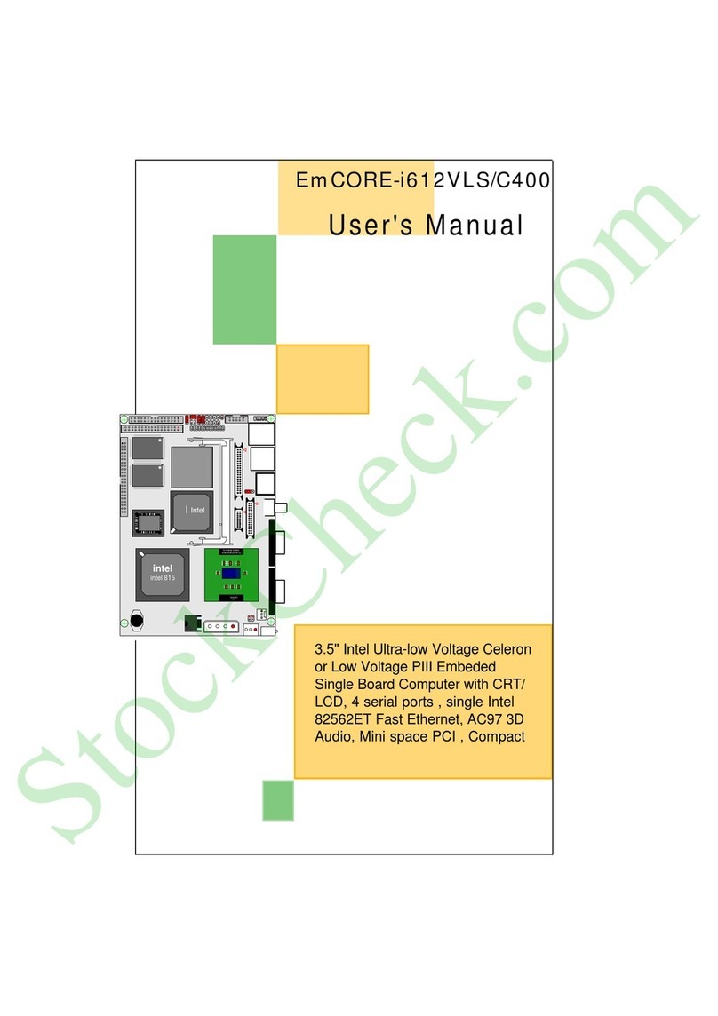
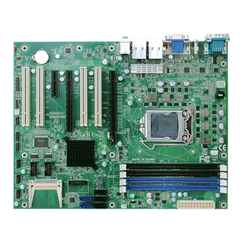
01 KBM1 06 CPUF1 11 DIO1 16 JFRT1 21 USB2 26 LAN1 31 LVDS1
02 KBM2 07 SATA1 12 SYSF1 17 JV1 22 LPT1 27 LAN2 32 VGA1
03 ATXP1 08 SATA2 13 JFSB1 18 CON1 23 IR1 28 JPWR1
04 DIMM1 09 JBAT1 14 PCIE1 19 JRS1 24 AUDIO1 29 JVLCD1
05 DIMM2 10 IDE1 15 MINIPCI1 20 USB1 25 COM1 30 INV1
Audio-In
Audio-Out
MIC-In
111
+
+
49
4833
32
64
1
16
17
49
48
33
32
64
1
16
17
4
65
321
12
10
9
11
78
26
13
14
1
2
1
1
2
3
124
1
1
8
1
2
3
4
7
6
5
+
3
1
2
3
4 5
6
8
12
14
16
7
17
11
19
20 21
23
24 25 26 27
28 29
32
31
30
18
15
22
9
13
10
Solder Side
Compact Flash Connector (CFD1)
Note: Does not support hot swap.
Pin Description Pin Description
1 GND 26 N/C
2DATA3 27DATA11
3DATA4 28DATA12
4DATA5 29DATA13
5DATA6 30DATA14
6DATA7 31DATA15
7 CS#1 32 CS#3
8 GND 33 N/C
9 GND 34 IO READ
10 GND 35 IO WRITE
11 GND 36 +5V
12 GND 37 IRQ15
13 +5V 38 +5V
14 GND 39 CSEL
15 GND 40 N/C
16 GND 41 IDE RESET
17 GND 42 IO READY
18 ADDR2 43 REQ
19 ADDR1 44 ACK#
20 ADDR0 45 ACT#
21 DATA0 46 DIAG
22 DATA1 47 DATA8
23 DATA2 48 DATA9
24 N/C 49 DATA10
25 GND 50 GND
