Contemporary Research ICC-HE User manual

17630 Davenport Road, Suite 113 • Dallas, TX 75252
Phone:972-931-2728 • Toll-Free: 888-972-2728 • Fax: 972-931-2765
E-Mail: Sales@crwww.com • Website: www.crwww.com
Product Manual
ICC-HE
Head-End Network Controller
Ver. 3.1 June 27, 2007

Contemporary Research 2 ICC-HE Head End
Table of Contents
Overview.............................................................................................................................................3
New Features (3.1).................................................................................................................................3
Specifications......................................................................................................................................4
Physical.................................................................................................................................................4
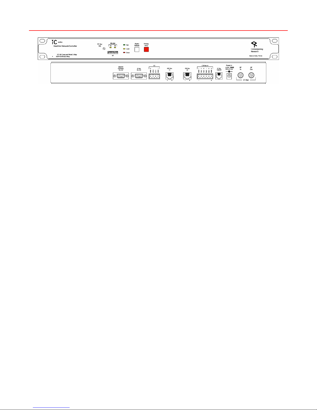
Front Panel............................................................................................................................................4
Control Connections ...............................................................................................................................5
iCW-Net Connections..............................................................................................................................5
iCC-Net Connections...............................................................................................................................6
Power Connections.................................................................................................................................6
Includes ................................................................................................................................................6
Installation .........................................................................................................................................7
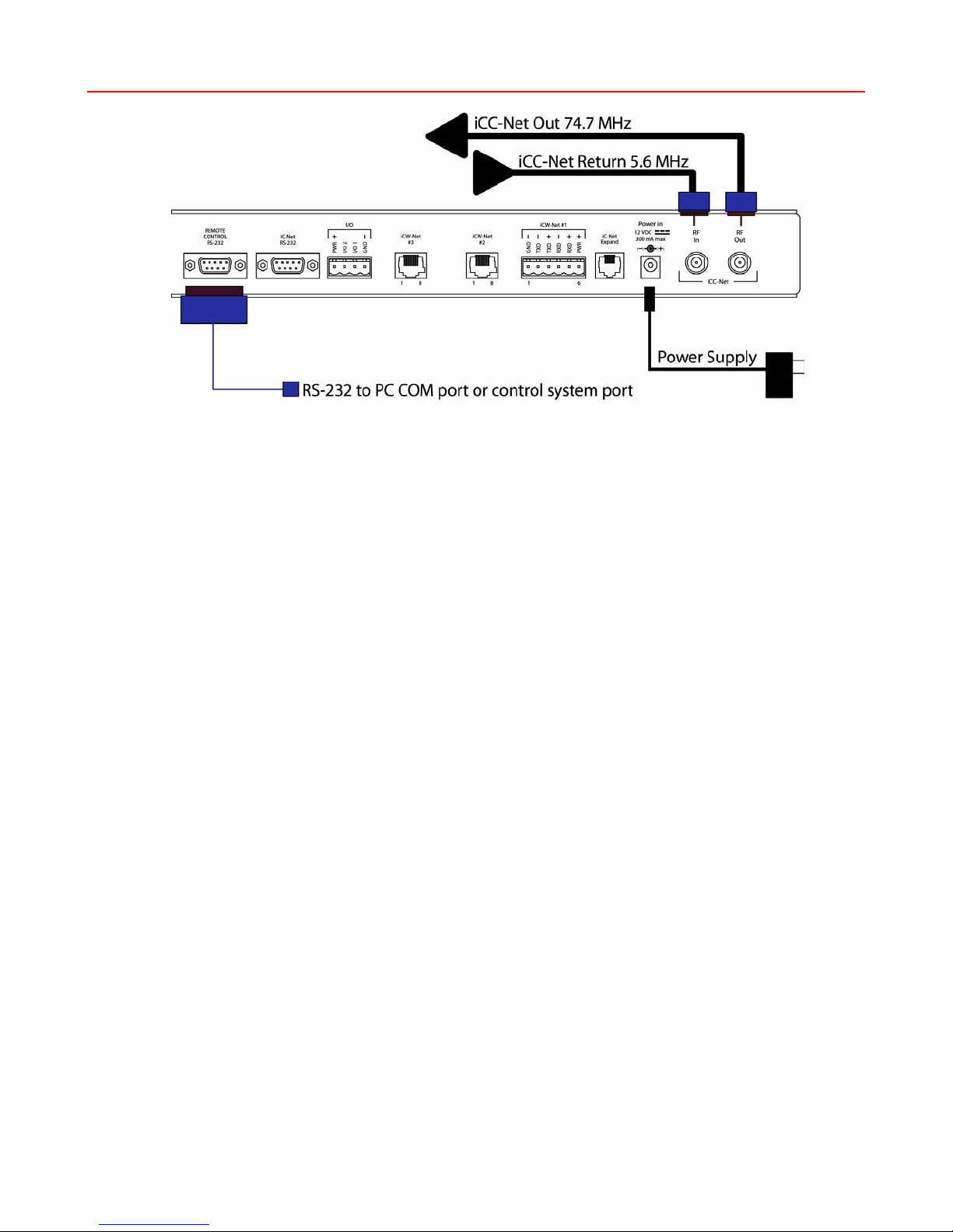
Remote Control Connection.....................................................................................................................7
RF Coax and iCC-Net Operation...............................................................................................................7
AC Power and Net LED operation.............................................................................................................7
I/O Port Connection................................................................................................................................7
RS-232 Terminal Commands ..............................................................................................................8
RS-232 Control Protocol.....................................................................................................................9
Overview...............................................................................................................................................9
Command String Structure......................................................................................................................9
Command format ...................................................................................................................................9
RS-232 HE Commands......................................................................................................................10
RS-232 Controller Commands ..........................................................................................................11
General Commands ..............................................................................................................................11
Audio Commands .................................................................................................................................12
Channel Commands..............................................................................................................................13
Tuning Commands ...............................................................................................................................14
On-Screen Text Commands...................................................................................................................15
RS-232 Response..............................................................................................................................16
Response String Structure.....................................................................................................................16
RS-232 HE Response ........................................................................................................................17
RS-232 Device Response..................................................................................................................18
iC-Net SmartZones............................................................................................................................20
System Map ......................................................................................................................................21
Typical RF and ICC-Net Signal Flow .................................................................................................22
Safety Instructions...........................................................................................................................23
Limited Warranty and Disclaimer.....................................................................................................24
RF Channel Frequencies ...................................................................................................................25

Overview
The ICC-HE Head-End Network Controller converts RS-232 protocol for 2-way distribution over RF coax, twisted
pair wiring, and RS-422. The ability to network TVs, video projectors, and large-screen video displays over the
existing CATV coax cable simplifies the creation of large-scale distributed TV control systems by eliminating the
need to run additional control wiring. Employing clear-channel RF frequencies to transmit and receive data, the
iCC-Net network is compatible with most CATV systems without conflict with existing channels. The bi-
directional network operates over a standard low-split cable system, simplifying installation and support.
The iC-Net network can also be distributed as iCW-Net over Category 3/5 wiring or RS-422/RS-232 connections.
Three iCW-Net ports are included, each capable of connecting thousands of ICW-Net format controllers over
wiring runs of up to 3,300 feet (1 Km). In addition, iCW-Net data can be sent to remote locations over RS-422
fiber and RS-232 video conferencing codec data ports.
•Networks with up to 4,000 TVs through wired iCW-Net and broadband CATV iCC-Net networks
oiCC-Net operates through same CATV coax as TV channels, requires no additional wiring
oiCW-Net distributes data over Category 5 or 3 wiring, fiber optic cable, or codecs
•Sends commands to individual devices, zones, or all units from a single RS-232 port
•Interacts with CR ABC Media Retrieval Systems, iC Commander software, or custom control systems
•Includes local control buttons and I/O ports that can trigger events in PC software or control systems
•Provides LED feedback for network, control, and operation status
•Employs new S12-series processing, offering software-upgradeable firmware and improved operation
New Features (3.1)
•New Check RF Levels (AR–page 8) command measures the level of background RF at 5.6MHz,
sends a reply that stated background RF level and current RF sensitivity setting.
Contemporary Research 3 ICC-HE Head End

Specifications
Physical
Size: 19" [483mm] wide x 1.75" [38mm] height (1RU) x 9" [229mm] deep
Weight: 3 lbs [1.36kg]
Enclosure: All aluminum with durable black powder coat paint
Mounting: Shelf or 19” equipment rack (mounting brackets included)
Front Panel
RF Out Adjust: Trims iCC-Net channel output, shipped set to +55 dBmV (max)
RS-232 TX LED: Yellow LED, lights when receiving RS-232 data on Remote Control RS-232 port
RS-232 DIP Switch: Sets RS-232 baud rate (9600 - 38.4K), 8 data bits, no parity, 1 stop bit
Selects high/low sensitivity for RF In signal
DIP Off On
1 RF In Low* RF In High
2
3
4
5
6 Baud
7 Baud
8 Baud
Baud 6 7 8
38,400 ON ON ON
19,200* OFF ON ON
9,600 ON OFF ON
4,800 OFF OFF ON
2,400 ON ON OFF
1,200 OFF ON OFF
*Default setting
Net LED: Green LED for iC-Net bus, flashes once per second if network is operating, device
numbers expected agree
The LED will flash twice per second if the number of present and expected devices do
not match
COM LED: Yellow LED blinks when a valid command is received or system response sent through
the Remote Control RS-232 port
Error LED: Red LED indicates a problem within the unit
Reset/Default: White button sends press and release RS-232 response to PC software or control
system
Emergency: Red button sends press and release RS-232 response to PC software or control system
Contemporary Research 4 ICC-HE Head End

Control Connections
Control RS-232: DB9 female, RS-232 data link to control system or PC
5 GND
2 RXD
3 TXD RXD 2
GND 5
TXD 3
9-pin D-sub
female
RS-232
Control Port
iC-Net RS-232: DB9 female, RS-232 data link to send iCW-Net over fiber or codec
I/O 1 & 2: 4-pin captive screw terminal for Input/Outputs 1 and 2
2 switch closures or inputs, max 50 mA, 24 VDC, switch to GND
1 – +12 VDC
2 – Output 2
3 – Output 1
4 – GND
I/O Applications: DC power – close pins 1 & 3 to provide DC on/off
Dry closure 2 – close pins 3 & 4 for dry contact to external power relay,
AMX PC1 or similar
Sense closure (3 & 4) on Input 1 – trigger control system to power off for all rooms
iCW-Net Connections
iCW-Net 2, 3 RJ-45 female 8 pin Telco jack, supports 3300 ft [1 km] of wire
RS-422/485 type data requiring at least 2 twisted wire pairs with shield or fifth
conductor
iCW-Net 1: 6-pin captive-screw terminal for system wiring or use with RS-422/485-format fiber or
codecs
iC-Net Expand RJ-11 female 6-pin Telco jack
Recommended Wire: CAT5/CAT3 compatible unshielded, max 3,300 feet [1 Km] from Head End
Contemporary Research 5 ICC-HE Head End

Contemporary Research 6 ICC-HE Head End
iCC-Net Connections
RF In: ‘F’, female, 75 ohm impedance, RF and iCC-Net from CATV system
Data Receive: Carried over the same RF coax connection as TV channels
Return signal from system controllers
Sub-band, 5.6MHz, narrow-band signal below standard sub-band channels
-15 to +35 dBmV signal level (0 to +15 dBmV nominal)
RF Out: F’, female, 75 ohm impedance, RF to CATV distribution to TVs, tuners, and controllers
Data Transmit: Mid-band VHF, 74.7 MHz, narrow-band signal between channels 4 and 5
±80 KHz max carrier deviation
+55 dBmV maximum (default)
Power Connections
Power In: 2.1mm coaxial jack (inside center conductor positive),
11 to 18 VDC, 12 VDC typical, 300 mA maximum (may be unregulated)
UL/CSA listed wall power supply (included for domestic 110 VAC/60 Hz shipments only)
Includes
10 dB RF attenuator
12 VDC Power Supply

Installation
Remote Control Connection
1. Attach appropriate RS-232 cable to Remote Control RS-232 port. See page 4 for RS-232 cable wiring diagram.
2. Set desired baud rate on front-panel DIP switch. Default setting is 19.2K baud – see page 4 for DIP switch setting
information.
RF Coax and iCC-Net Operation
1. Connect an RF coax feed from RF Out to the system’s RF combiner, mixing the iCC-Net Out signal with the other
CATV channels. The iCC-Net Out channel operates at 74.7 MHz, in between cable channels 4 and 5.
2. In most applications, the installer will connect the included 10 dB attenuator in between, trimming the He’s standard
55 dB output to 45 dB.
3. Using an RF signal level meter, use the front panel RF Out adjustment counterclockwise to match the RF Out signal to
the other CATV sources. Limit RF Out adjustment to -10 dB, using attenuators to achieve a lower signal strength.
4. Add a Sub-CATV Diplexer after the CATV amplifier.
5. Connect the Sub-Channel output of the Diplexer to the HE RF In connection.
6. Using a terminal emulator, send an AR command (p8) a few times to measure the level of background RF compared
to the current Sensitivity setting (DIP switch 1, p4).
7. Set one iC-Net controller to constantly transmit using iC ToolKit. Send the AR command again the measure the level
at Constant Transmit.
8. The Sensitivity level should be set in-between the background RF and constant transmit levels.
AC Power and Net LED operation
1. Insert DC power supply plug into the Power In jack.
2. Plug power adaptor into AC wall outlet, the front-panel LEDs should turn on momentarily.
3. If iC-Net communication is functioning, the Net LED will flash once per second, or twice per second (the double-flash,
indicating a difference between present and expected device, would be typical in the initial phase of the installation.)
I/O Port Connection
1. A simple contact closure can be wired to I/O 1 or 2, a press or release can trigger events in the PC or control system
software.
2. In other applications, the I/O ports can act as closure outputs, activating an external power relay, 2x1 video switcher
or other device.
3. You’ll have to choose application – the ports act as either an output or input, not both. See Control Connections on
page 4 for wiring and rating information.
Contemporary Research 7 ICC-HE Head End

Contemporary Research 8 ICC-HE Head End
RS-232 Terminal Commands
Employ standard Windows Terminal program, set to baud rate match DIP switch setting on front of HE.
Command Description
Commands shown in ASCII and end with carriage return
(Decimal 13, Hex $0D, or Enter key).
Response displays * character to signify end of characters, or times out if no
characters are received after 2 seconds.
Tip: Just hit Enter to repeat any Terminal command.
Echo Enable EN Enables character echo so you can see typed characters on screen.
Echo Disable EF Disables terminal character display (default).
Version VE
ID Displays HE software version.
Reset Z! Performs system reset.
Show Devices
SD Displays list of 2-way devices stored in HE memory. List can be created by iC
Commander software, ABC-MRC software, or Scan and Build command below.
Example Response: Devs Present:
257-261
263
265-271*
Show Missing SM Displays list of missing 2-way devices (compared to HE memory list).
Example Response: Devs Missing:
262 -263
264*
Show Present SP Displays number of present devices and number of devices expected.
Example Response: Num Devs Present : 1
Num Devs Expected : 53
Scan and Show SZ Scans iC-Net and displays list of all 2-way devices found (does not change HE
memory).
Scan and Build Z^ Scans iC-Net and saves list of all 2-way devices found into HE memory.
Show Log L Returns four hex bytes, separated by commas. If any of the bytes change as you
repeat the command, there is likely an error in return communication from iC-Net
devices.
Clear Log DL Clears the L hex bytes to zero.
Check RF
Receive Level AR Level RF Received (idle)
Example Responses:
AR RRRR/SSSS = Receive/Sensitivity levels
AR 0321/1337 = 0.321V “quiet” receive level, 1.337V high threshhold
AR 0321/0693 = 0.321V “quiet” receive level, 0.693V low threshold
AR 2250/0693 = 2.251V constant transmit receive level, 0.693V low threshold
This command is used to check RF levels at 5.6MHz, compared to the current
sensitivity level setting (DIP Switch 1, page 4). Test the RF receive level a few times
when the iC-Net units are not transmitting, then again when one iC-Net unit is set to
constantly transmit. The Sensitivity level should fall about halfway between quiet
and constant transmit RF levels.

Contemporary Research 9 ICC-HE Head End
RS-232 Control Protocol
Overview
RS-232 control for up to 4000 iC-Net devices is provided through an iC series Head-End Network Controller. The
ICC-HE Head-End manages iC-Net communication over RF Coax to ICC-series devices as well as ICW-series
devices over twisted-pair Cat3/5 wiring. The ICW-HE Head-End operates on the Cat5 network only.
Each device is assigned a unique device number from 1 to 4000 to which control commands are addressed. The
devices are organized into 16 zones of 255 devices. All the devices in each zone will respond to a single “virtual
device number” — one device number that represents all devices in each zone. There is also a global device
number, 4095, that will command all devices in the system. This feature dramatically speeds up system
operation and programming, because one command can affect an entire group of devices—or all. To take
advantages of this feature, review the section iC-Net Zones in this manual.
In ABC Media Retrieval Systems, we reserve the first group of devices, 1-255, for components operating on a
connected control system. Zones 1-16 are used for CR TV Controllers, Video Display Controllers and Tuners. As
it’s unlikely any system will use all 4000 devices, this may be a good device standard for your system as well.
The Remote RS-232 port on the Head-End Network Controller can communicate from 1200 to 38.4K baud. The
factory default setting is 19.2K baud, 8 data bits, No parity, and 1 stop bit.
Command String Structure
Characters in command strings are expressed
in a combination of hex and ASCII characters.
•Single-byte hex numbers are preceded
by the ‘$’ symbol
•ASCII characters or strings are
enclosed in single quotes
•Numbers not marked as hex or ASCII
are a single decimal byte
•Parameters shown in < > brackets are
single byte
•A series of multiple commands or
parameters are set apart by [ ]
brackets
•Commas separate the bytes, but are
not part of the protocol
•Double quotes enclose the command
string, but are not part of the protocol
Command format
“$A5,<dh>,<dl>,<ncb>,<cmd1>,<parameter> [<cmdN>]"
$A5 Starts the command
<dh> The zone or high order byte of the device
<dl> The unit or low order byte of the device (0
for global zone)
<ncb> The number of command bytes to follow
<cmd1> The first command byte
<parameter> Command parameters (not used by all
commands)
[<cmdN>] Multiple commands can be concatenated,
with byte count added to <ncb>

Contemporary Research 10 ICC-HE Head End
RS-232 HE Commands
The following commands apply to the HE only. Commands addressed to controllers are included with the
Product Manual for the specific device.
Command Description
Closures Y_ “$A5,0,0,3, ‘Y’ <I/0 Port>’ ” (7 bytes)
Turns the two internal closures on and off. Closure 1 is typically used to
control the optional buzzer, Closure 2 typically used to control an external
camera power relay.
“$A5,0,0,3, ‘Y10’” turns Closure 1 off
“$A5,0,0,3, ‘Y11’” turns Closure 1 on
“$A5,0,0,3, ‘Y20’” turns Closure 2 off
“$A5,0,0,3, ‘Y21’” turns Closure 2 on
Device Status SP "$A5,0,0,2,'SP'" (6 bytes)
Queries the Head-End for the number of devices present on the network and
the number of devices expected.

Contemporary Research 11 ICC-HE Head End
RS-232 Controller Commands
The following commands summarize RS-232 commands to iC-Net controllers. There is a high degree of
compatibility between Contemporary Research devices; most commands execute a similar action or response in
nearly all units. Refer to each unit’s Product Manual for specific programming information.
General Commands
Command Description ICC
IRC ICC
VDC PRZ
PSC
ZS2
ICC1
IR/232
Power Off PO “$A5,<dh>,<dl>,2,’P0’ ” (6 bytes) – checks status for true power control X 3 X X X
Power On P1 “$A5,<dh>,<dl>,2,’P1’ ” (6 bytes) – checks status for true power control X 3 X X X
Power Toggle PT “$A5,<dh>,<dl>,2,’PT’ ” (6 bytes) – checks status for true power control X 3 X X X
Mono/Stereo S7 “$A5,<dh>,<dl>,3,’S7’, <mode>” (7 bytes) 0=mono, 1=stereo
Bass Gain S8 “$A5,<dh>,<dl>,3,’S8’, <mode>” (7 bytes) Sets bass gain
Treble Gain S9 “$A5,<dh>,<dl>,3,’S9’, <mode>” (7 bytes) Sets treble gain
RS-232
Display Type T0 “$A5,<dh>,<dl>,3,’T0’<type> ” (7 bytes) – Sets RS-232 control codes
Identical to on-screen menu 45700 command for VDC.
X
IR Device
Type T1 “$A5,<dh>,<dl>,3,’T1’<type> ” (7 bytes) – Sets IR device type
Identical to on-screen menu 45700 command for IR-format controllers. X
X
Closures Y- “$A5,<dh>,<dl>,3, ‘Y’ <I/0 Port>’ ” (7 bytes)
Turns the two internal closures on and off. Closure 1 is typically used to control
the optional buzzer, Closure 2 typically used to control an external camera power
relay.
“$A5,<dh>,<dl>,3, ‘Y10’” turns Closure 1 off
“$A5,<dh>,<dl>,3, ‘Y11’” turns Closure 1 on
“$A5,<dh>,<dl>,3, ‘Y20’” turns Closure 2 off
“$A5,<dh>,<dl>,3, ‘Y21’” turns Closure 2 on
X X X X
Control Lock LM “$A5,<dh>,<dl>,3,'LM',<control>” (7 bytes)
Locks out front panel and IR remote control functions.
Bit 7 Selects IR remote control operation (0=enabled, 1=disabled)
Bit 6 Selects volume control operation (0=enabled, 1=disabled)
Bit 5 - 1 Always 0
Bit 0 Selects front panel button operation (0=enabled, 1=disabled)
X X X 2
Control String UX "$A5,<dh>,<dl>,2+string length>,'UX'<string>" (variable bytes)
Sends an RS-232 string (ASCII, decimal, or hex) directly to the TV display.
Ex: "$A5,1,2,6,'UX, 'PON', 13" Sends PON, followed by carriage return (device
258)
X
Device Status SP "$A5,0,0,2,'SP'" (6 bytes)
Queries the Head-End for the number of devices present on the network and the
number of devices expected.
X X 1 1
Notes 1
2
3
1-way units do not respond to command
Zenith LM Bit 7 affects both IR control and front panel lockout
VDC sends discrete power on and power off commands

Contemporary Research 12 ICC-HE Head End
Audio Commands
Command Description ICC
IRC ICC
VDC PRZ
PSC
ZS2
ICC1
IR/232
Volume
VL “$A5,<dh>,<dl>,3,’VL’,<vol level>” (7 bytes)
Sets volume level
0 = Mute
1 – 63 = Minimum level (1) to maximum volume (63)
X X X X X
Ramp Up
VU “$A5,<dh>,<dl>,2,’VU’ ” (6 bytes)
Starts volume ramping up X X
Ramp Down
VD “$A5,<dh>,<dl>,2,’VD’ ” (6 bytes)
Starts volume ramping up X X
Stop Ramp
VV “$A5,<dh>,<dl>,2,’VV’ ” (6 bytes)
Stop volume ramp X X
Mute On VM “$A5,<dh>,<dl>,2,’VM’ ” (6 bytes)
Mutes volume X X
Mute Off VX “$A5,<dh>,<dl>,2,’VX’ ” (6 bytes)
Unmutes volume X X
Toggle Mute VT “$A5,<dh>,<dl>,2,’VT’ ” (6 bytes)
Toggles between mute on and off X X
Save Level VW “$A5,<dh>,<dl>,2,’VW’ ” (6 bytes)
Save current volume level, default when unit powers up
To power-up to last level, set volume to zero (VL) and save.
X X
Power-up
Volume S5 "$A5,<dh>,<dl>,3,'S5',<volume>" (7 bytes)
Sets volume level when unit powers up
0 = restore to previous level
1 – 63 = Set from minimum (1) to maximum level (63)
X X
Mono/Stereo S7* “$A5,<dh>,<dl>,3,’S7’, <mode>” (7 bytes) 0=mono, 1=stereo
Bass Gain S8* “$A5,<dh>,<dl>,3,’S8’, <mode>” (7 bytes) Sets bass gain
Treble Gain S9* “$A5,<dh>,<dl>,3,’S9’, <mode>” (7 bytes) Sets treble gain
Notes * Reserved for future stereo iC-Net products

Contemporary Research 13 ICC-HE Head End
Channel Commands
Command Description ICC
IRC ICC
VDC PRZ
PSC
ZS2
ICC1
IR/232
Ts & Qs The following T-series channel commands select a channel and display the
channel label on the TV, while Q-series commands don’t show the on-
screen text. ICC1-IR does not provide channel labels.
T Channel
Up TU “$A5,<dh>,<dl>,2,’TU’ ” (6 bytes)
Tunes to next channel up in Tune Ring X X X X X
T Channel
Down TD “$A5,<dh>,<dl>,2,’TD’ ” (6 bytes)
Tunes to next channel down in Tune Ring X X X X X
T Channel
Previous TP “$A5,<dh>,<dl>,2,’TP’ ” (6 bytes)
Tunes to previous channel in Tune Ring X X X X X
Force T Chan TC “$A5,<dh>,<dl>,3,’TC’, <channel>” (7 bytes)
Tunes to a specific channel
124 = RGB 2 input on TV
125 = RGB input on TV
126 = Select external A/V input (IRC/VDC also selects TV video input)
127 = Select S-Video Input
0 = Blank video output to TV
255 = Unblank TV video (restore to previous channel)
Tip: Not all inputs are available on every TV make and model.
X X X X X
Select T
Chan TT “$A5,<dh>,<dl>,2,’QT’,<channel>” (7 bytes)
Tunes channel if included in TR X X X X X
Channel
Query T? “$A5,<dh>,<dl>,2,’T?’ ” (6 bytes)
Request response for current channel X X
Q Channel
Up QU “$A5,<dh>,<dl>,2,’QU’ ” (6 bytes)
Tunes to next channel up in Tune Ring X X X X X
Q Channel
Down QD “$A5,<dh>,<dl>,2,’QD’ ” (6 bytes)
Tunes to next channel down in Tune Ring X X X X X
Q Channel
Previous QP “$A5,<dh>,<dl>,2,’QP’ ” (6 bytes)
Tunes to previous channel in Tune Ring X X X X X
Force Q
Chan QC “$A5,<dh>,<dl>,3,’QC’, <channel>” (7 bytes)
Tunes to a specific channel
Same special-function channels as in the T Channel Select section above
X X X X X
Select Q
Chan QT “$A5,<dh>,<dl>,2,’QT’,<channel>” (7 bytes)
Tunes channel if included in TR X X X X X
Tuning Style H1 “$A5,<dh>,<dl>,3,’H1’,<style>” (7 bytes)
1 = 5-digit CableCard style tuning (1-9999)
2 = Virtual HD Major-Minor tuning (tunes to virtual channel ID in display)
3 = Physical HD Major-Minor tuning (physical channel, minor digital)
X
TC Response H2 “$A5,<dh>,<dl>,3,’H2’,<response>” (7 bytes)
This pre-sets how the ICC1-232/IR will respond to TC tuning commands.
0= Ignore, use current settings
1= Analog (XX-0)
2= Digital (XX-1)
X
Tune HD TH
Ex:
“$A5,<dh>,<dl>,5,’TH’,<H1>,<Major>,<Minor>” (9 bytes)
Normally, the H1 parameter is 0, allowing the ICC1-232 to use the current
H1 tuning format, but it could be used to force a different tuning option.
When the display is set to the H1=1 mode, the Major-Minor bytes will
represent the high and low bytes of the 5-digit number. In H1=2 or 3
modes, the bytes represent the Major and Minor channel numbers. Values
may be in hex or decimal.
“$A5,1,4,5,’TH’,1,2,3” Device 260, channel 515
“$A5,1,4,5,’TH’,2,2,3” Device 260, virtual channel 2-3
“$A5,1,4,5,’TH’,3,2,3” Device 260, physical channel 2, minor 3
X

Contemporary Research 14 ICC-HE Head End
Tuning Commands
Command Description ICC
IRC ICC
VDC PRZ
PSC
ZS2
ICC1
IR/232
Operating
Parameters TM “$A5,<dh>,<dl>,3,’TM’,<setting>” (7 bytes)
Sets up key functions in the unit
bit 7 = Selects TV frequency tuning mode, 0=CATV, 1=Broadcast/Antenna
bit 6 – 3 = 0
bit 2 = Channel up/down operation, 0=Tune Ring, 1=Send IR Keypad response
bit 1 = Numeric channel labels, 0=num labels off, 1=num labels on)
bit 0 = Alpha channel labels, 0=alpha labels off, 1=alpha labels on
4 4 1 1
Tuner Mode SO "$A5,<dh>,<dl>,3,'S0',<tune mode>" (7 bytes)
Sets tuner mode to CATV or Broadcast/Antenna
0 = CATV
1 = Broadcast/Antenna
2 = HRC
3 = IRC
X X
Marquee
Chan T2 “$A5,<dh>,<dl>,3,’T2’<channel> ” (7 bytes) – Sets default power-up channel
Sets default channel selected when unit powers up X
X
X
Video Loss
Detection Q2 "$A5,<dh>,<dl>,3,'Q2',<video loss mode>" (7 bytes)
Selects response when a loss of video signal is detected
0=Both audio and video muted (default-blue screen for video)
1=Audio muted only
2=Video muted only
3=No muting (do nothing on loss of video)
X X
Tuner Mode SO "$A5,<dh>,<dl>,3,'S0',<tune mode>" (7 bytes)
Sets tuner mode to CATV or Broadcast/Antenna
0 = CATV
1 = Broadcast/Antenna
2 = HRC
3 = IRC
X X X
Tune Ring TR “$A5,<dh>,<dl>,<ncb>,’TR’, [<chan 1>, <chan N>]” (variable bytes)
This command stores a Tune Ring, a series of preset channels accessed by
channel up/down commands.
Ex1: “$A5,<dh>,<dl>,6,’TR’, 5,4,8,11” sets ring to channels 5, 4, 8 and 11
Tip: The ring follows the stored order, channels do not have to be in
ascending order
Ex2: “$A5,<dh>,<dl>,2,’TR’ ” clears the Tune Ring, locks unit to current channel
Tip: In the above mode, the IR Keypad channel up/down response to the
Head-End, so the system will know the user is trying to change
channels. In response, the system could change channels on a media
sources, like a VCR or satellite. See K response note in
RS-232
Responses.
Ex3: “$A5,<dh>,<dl>,9,’TR’, $82,5,7,$89,13” sets channels 2-5, 7, and 9-13.
You can specify a range using MSB bit for the first channel; the next byte is the
last.
X X 1 1 2
Channel
Labels TN “$A5,<dh>,<dl>,<ncb>,‘TN’,<channel>,<label>” (variable bytes)
Stores an ASCII string as the channel label. The text will appear briefly when the
channel is selected, if the feature has been activated by TM command.
Ex1: “$A5,<dh>,<dl>,6,‘TN’, ‘7’, ‘PBS’ ” unit displays PBS when 7 is selected
Ex2: “$A5,<dh>,<dl>,3,‘TN’, ‘7’ ” Clears alpha label for channel 7
Ex3: “$A5,<dh>,<dl>,4,‘TN’,0,0” Clears all alpha labels
X X X X
Display Label TC “$A5,<dh>,<dl>,2,’TC’ ” (6 bytes) – Displays channel label for about 15 sec X X X X
Notes 1
2
4
1-way units do not send the TM K keypad responses for bit 2
Analog tune ring only, of limited use in 1-way controller
IRC/VDC ignores TM Bit 7 (tuning), SO command sets tuning mode

Contemporary Research 15 ICC-HE Head End
On-Screen Text Commands
Command Description ICC
IRC ICC
VDC PRZ
PSC
ZS2
ICC1
IR/232
Write Text DM “$A5,<dh>,<dl>,<ncb>,‘DM’, <start line>,<text color>,<background color>,
<background>,<size and shadow>,<timeout>,<message bytes>” (variable
bytes)
Clears current text, displays text message over video (default) or blank
background. The built-in character generator can accept up to 40 characters of
text (including carriage returns), 28 characters per line. Use a hex $0D or
decimal 13 in the text as a carriage return, which will advance CG to the next
line, first space on the right.
Start Line - 1-11
Text Color - 1-7= White
Text Background Color – 0-7=Transparent (no background)
Full screen background – 0=normal insert over video, 1=blank screen (blue)
Size and Shadow – 0-3=small text with drop shadow
Time-Out – 0=15-second display, 1=persistent
Persistent text stays on screen until the next DM, or new Menu or channel.
Ex1: “$A5,<dh>,<dl>,10,‘DM’, 2,7,0,0,1,0,’TEST’ ” displays the word TEST on
the second line, white text, inserted over video, small size with drop shadow,
and timing out after 15 seconds.
Ex2: “$A5,<dh>,<dl>,2,‘DM’ ” clears on-screen display, also clears persistent
text
The IRC and VDC use white text and clear backgrounds when it receives a Text
or Background Color parameter between 1 and 7, and accepts values 0-3 for
text size and shadow. This allows compatibility with Smart TVs mixed in the
same system that can display other colors and fonts.
5 5 X X
Advanced The following commands provide advanced CG text operation
Fast Write DN “$A5,<dh>,<dl>,<ncb>,’DN’, <text> ” (variable bytes)
Clears display, writes specified text starting at column 1, row 1. $0D and hex
$EA, $EB, $DC, and $DB can be included, operate same as matching
commands below.
X X
Write Here DW “$A5,<dh>,<dl>,<ncb>,’DW’, <text> ” (variable bytes)
Writes specified text starting at present cursor position. Accepts same Hex as
DN.
X X
Row, Column DG “$A5,<dh>,<dl>,4,’DG’, <row>, <column>” (8 bytes)
Moves the cursor to the specified row and column position. If row is 0, then
row will not be changed, and if column is 0, then column will not be changed.
X X
Cursor
Column E7 “$A5,<dh>,<dl>,3,’E7’, <column>” (7 bytes) – sends cursor to specified
column. X X
Cursor Row E8 “$A5,<dh>,<dl>,3,’E8’, <row>” (7 bytes) – sends cursor to specified row. X X
Return EB “$A5,<dh>,<dl>,2,’EB’ ” (6 bytes)
Moves cursor down to the first column of the next row.
X X
Clear All EA “$A5,<dh>,<dl>,2,’EA’ ” (6 bytes)
Clears display, sends cursor to column 1, row 1.
X X
Clear to End DC “$A5,<dh>,<dl>,2,’DC’ ” (6 bytes)
Clear on-screen display from cursor to end of screen, position stays the same.
X X
Clear Line DB “$A5,<dh>,<dl>,2,’DB’ ” (6 bytes)
Clear on-screen display from cursor to end of line, cursor position stays the
same.
X X
Clear Spaces E9 “$A5,<dh>,<dl>,3,’E9’, <num spaces>” (7 bytes)
Clears specified number of spaces, starting from cursor to the right.
X X
Text Timeout DQ “$A5,<dh>,<dl>,3,’DQ’, <time>” (7 bytes)
Sets screen timeout to specified time in seconds (1-254). If time is 0 or 255,
any text on the screen will persist indefinitely, or until cleared.
X X
Notes 5 IRC/VDC will respond to all formatting commands, using white text on
transparent background

Contemporary Research 16 ICC-HE Head End
RS-232 Response
Contemporary Research 2-way iC-Net devices will send a response over the network whenever there is there is
a change in status or command from an IR remote or front panel.
Response String Structure
Characters in response strings are expressed in a combination of hex and ASCII characters. For clarity, the
following protocol examples use the following conventions:
•ASCII characters or strings are shown enclosed in single quotes
•Numbers shown that are not in single quotes are a single decimal byte
•Parameters shown in < > brackets are single byte
•A series of multiple commands or parameters are set apart by [ ] brackets
•Commas separate the bytes, but are not part of the protocol
•Double quotes enclose the command string, but are not part of the protocol
Command format:
“ ‘<’,<dh>,<dl>,<nrb>,<rb1>, <para1> [<rbN>]"
‘<’ Starts the response
<dh> The zone or high order byte of the device
<dl> The unit or low order byte of the device (0 for global zone)
<nrb> The number of response bytes to follow
<rb1> The first response byte
<para1> Associated parameters, if any
[<rbN>] Multiple responses may be included

Contemporary Research 17 ICC-HE Head End
RS-232 HE Response
The following responses apply to the HE only.
Response Description
Key-I/O K “ ‘<’,0,0,2,'K',<IR Key>" (6 bytes)
Sent when the Reset or Emergency buttons are pressed, or when I/O 1 or 2
receives a closure. PC software or a control system connected to the Control RS-
232 port can receive the response and activate a programmed event.
101 = Reset button pressed 229 = Reset button released
102 = Emergency button pressed 230 = Emergency button released
103 = I/O 1 input closed 231 = I/O 1 input opened
104 = I/O 2 input closed 232 = I/O 2 input opened
Device Query SP " '<',0,0,4,'SP',<number devices present>,<number devices expected> (8 bytes)
Sent in response to HE Device Status query.
Tip: If the number of present and expected devices match, the green Net LED
on the HE will blink once per second. If the two numbers do not agree, the
LED blinks twice per second.

Contemporary Research 18 ICC-HE Head End
RS-232 Device Response
The following responses are common to all iC-Net 2-Way devices.
Response Description
New Channel T “ ‘<’,<dh>,<dl>,2,'T',<new channel>" (6 bytes)
Sent in response to T? command.
IR Function R “ ‘<’,<dh>,<dl>,2,'F',<IR Function>" (6 bytes)
Sent when unit receives a new function command is pressed (1-8) or released (0)
from the IR remote.
0 = Release
1 = Play
2 = Stop
3 = Pause
4 = Fast Forward
5 = Rewind
8 = Record
IR Key K “ ‘<’,<dh>,<dl>,2,'K',<IR Key>" (6 bytes)
Sent when unit receives a new key command is pressed (10-23) or released (0) from
the IR remote.
0 = Release 102 = Timer
10 - 19 = Numeric keypad entry 0 – 9 105 = Media Menu
21 = Enter 106 = Cursor Right
22 = Channel Up 107 = Cursor Left
23 = Channel Down 108 = Cursor Up
29 = Menu 109 = Cursor Down
101 = Previous Channel 110 = Media Select
The 0 – 9, Channel Up/Down functions are sent only if enabled in the TM command
(Bit 2 = 1). The Channel Up/Down responses will be sent if the Tune Ring contains
no channels – see Ex2 in the Tune Ring command section.

Contemporary Research 19 ICC-HE Head End
Response Description
IR Menu M “ ‘<’,<dh>,<dl>,5,'M',<msh>, <msl>, <mph>, <mpl>" (9 bytes)
Sent when unit receives a new Menu command is pressed or released (0) from the
IR remote. Menu Selection high and low bytes are in <msh> and <msl>. Menu
Parameter high and low bytes are in <mph> and <mpl>.
A Menu command is initiated by pressing the Menu key, followed by a numeric entry,
then the Enter or Channel Up key. During the Menu process, the Channel Down key
acts as a backspace or delete key.
Some selections that need only a single numeric entry and will have a parameter
value of zero (0). Those keys are 0, 8, 9, 18, 20, 30, 900, 911, and 912.
Menu selections that will prompt the user to enter a second parameter entry are:
1 = Select Media
2 = Password
3 = Chapter Search
4 = Frame Search
11 = Channel
21 = Page Zone
22 = Page Room
25 = Go
21 = Attach Zone
32 = Attach Room
Tip: The Menu entries are active even if the TV power is off.

Contemporary Research 20 ICC-HE Head End
iC-Net SmartZones
To simplify controlling groups of devices, iC-Net is divided into 16 zones of 255 devices, also called
SmartZones. All the devices within each zone can be controlled simultaneously by sending a command
to a single “virtual device number”.
For example, noting the SmartZone chart below, if we send a Power On command to device #256,
any TV controller numbered between 257 and 511 will instantly turn on. If we send a Power Off
command to device #4095, all devices in the system will turn off.
This is an immensely powerful feature, because most systems can only address one device at time. So
if you need to turn off all 50 TV in a zone, you would need to send 50 commands. In addition to the
hassles of creating multiple commands, there would be a long delay between the first and last
command. One command, instant response is easier.
ABC Media Retrieval Systems reserve Zone 0 for devices used in the central control system, 1 -15 for
iC-Net devices. This structure may be useful for your application, or you could use Zone 0 just like any
other iC-Net zone.
Zone First Device Last Device Virtual Device
1 257 511 256
2 513 767 512
3 769 1023 768
4 1025 1279 1024
5 1281 1535 1280
6 1537 1791 1536
7 1793 2047 1792
8 2049 2303 2048
9 2305 2559 2304
10 2561 2815 2560
11 2817 3071 2816
12 3073 3327 3072
13 3329 3583 3328
14 3585 3839 3584
15 3841 4000 3840
All Zones 4095
Tip: You've probably figured out that you never want to assign a virtual device number to an actual device
in the system. If you assigned #1536 to a device, all the TV controllers in Zone 6 would respond every
time you sent a command to that one device.
Other manuals for ICC-HE
2
Table of contents
Other Contemporary Research Network Hardware manuals