Contemporary Research ICC2-ATSC 4S User manual

Contemporary Research 1 ICC2-ATSC 4S
Product Manual
ICC2-ATSC 4S/ICC2-ATSC 4
HDTV Tuner/Controller
October 3, 2017
S12 Control Version 6.9
HD Processor Version 6.38

Contemporary Research 2 ICC2-ATSC 4S
Table of Contents
Setup Guide ................................................................................................................................................................ 3
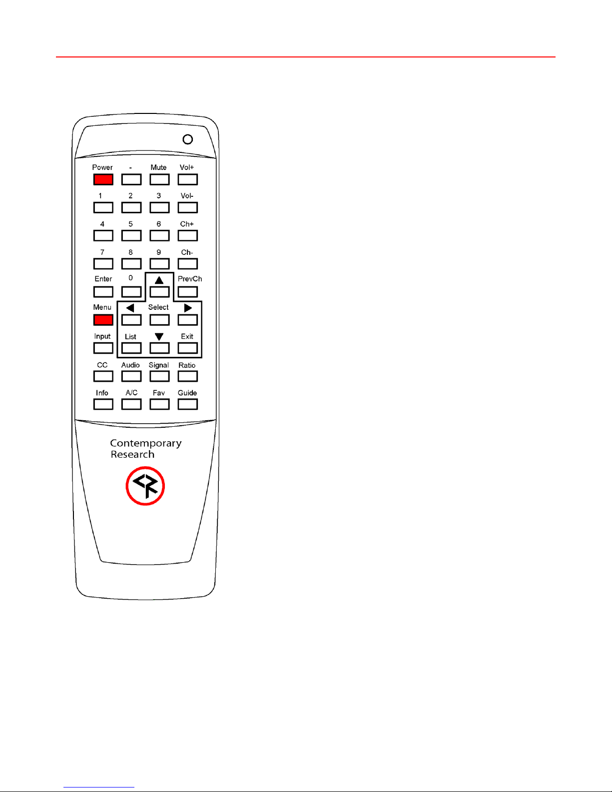
IR Remote Operation............................................................................................................................................... 3
FAQ ........................................................................................................................................................................... 4
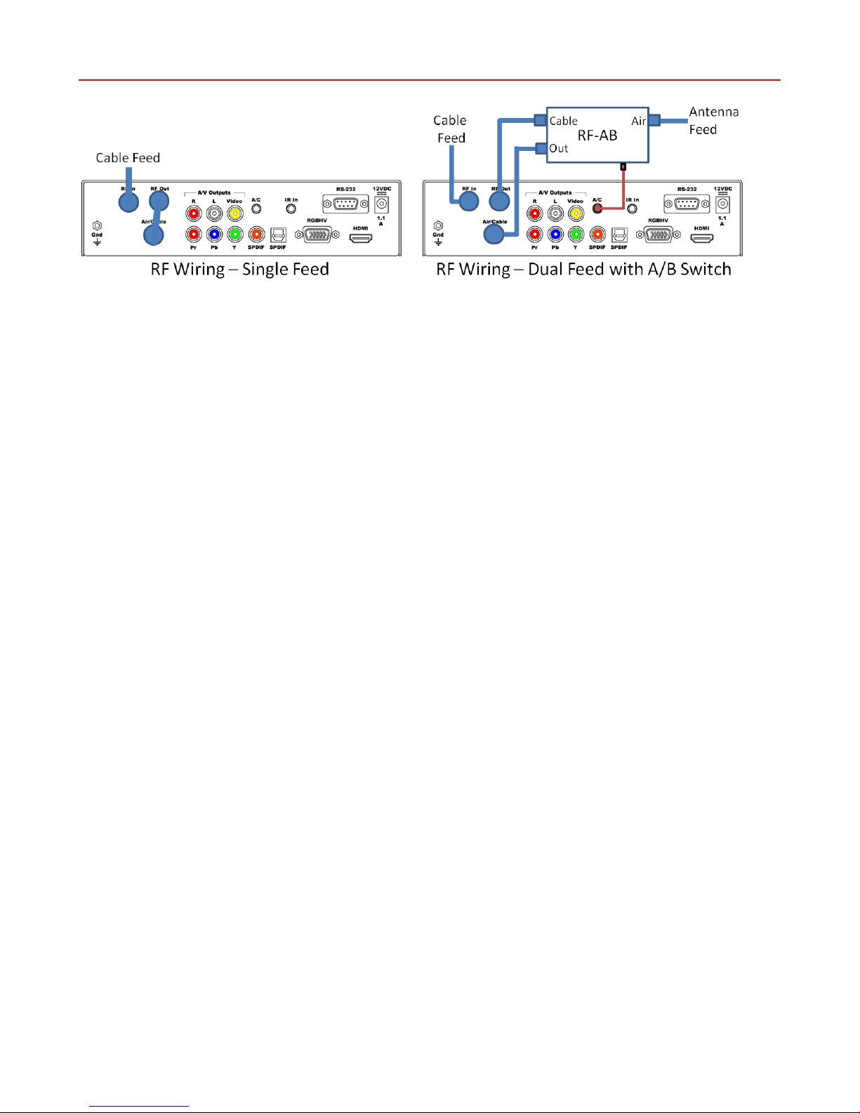
RF Wiring Options ........................................................................................................................................................ 5
Front Panel Setup......................................................................................................................................................... 6
RS-232 Control Library .................................................................................................................................................. 7
Input Selects .......................................................................................................................................................... 7
Input Command.....................................................................................................................................................77
HD2-RC IR Remote ....................................................................................................................................................... 9
iCC-Net Control Protocol ............................................................................................................................................. 10
Overview...............................................................................................................................................................10
Command String Structure......................................................................................................................................10
Command format:..................................................................................................................................................10
Writing Your Own Control Code...............................................................................................................................11
iCC-Net Commands..................................................................................................................................................... 12
Control..................................................................................................................................................................12
Tuning ..................................................................................................................................................................13
Tuning ..................................................................................................................................................................14
Text......................................................................................................................................................................14
HD2-RC Remote Emulation .....................................................................................................................................15
iCC-Net Response....................................................................................................................................................... 16
iCC-Net Zones, Units and Device Addresses..................................................................................................................... 17
System Map.............................................................................................................................................................. 18
On-Screen Menus....................................................................................................................................................... 19
Main Menu ............................................................................................................................................................19
Channel Menus ......................................................................................................................................................19
Caption Menus.......................................................................................................................................................20
V-Chip Settings Menus............................................................................................................................................20
Setup Menus .........................................................................................................................................................21
Overview.................................................................................................................................................................. 23
Specifications ............................................................................................................................................................ 24
Physical –ICC2-ATSC 4S ........................................................................................................................................24
Physical –ICC2-ATSC 4 ..........................................................................................................................................24
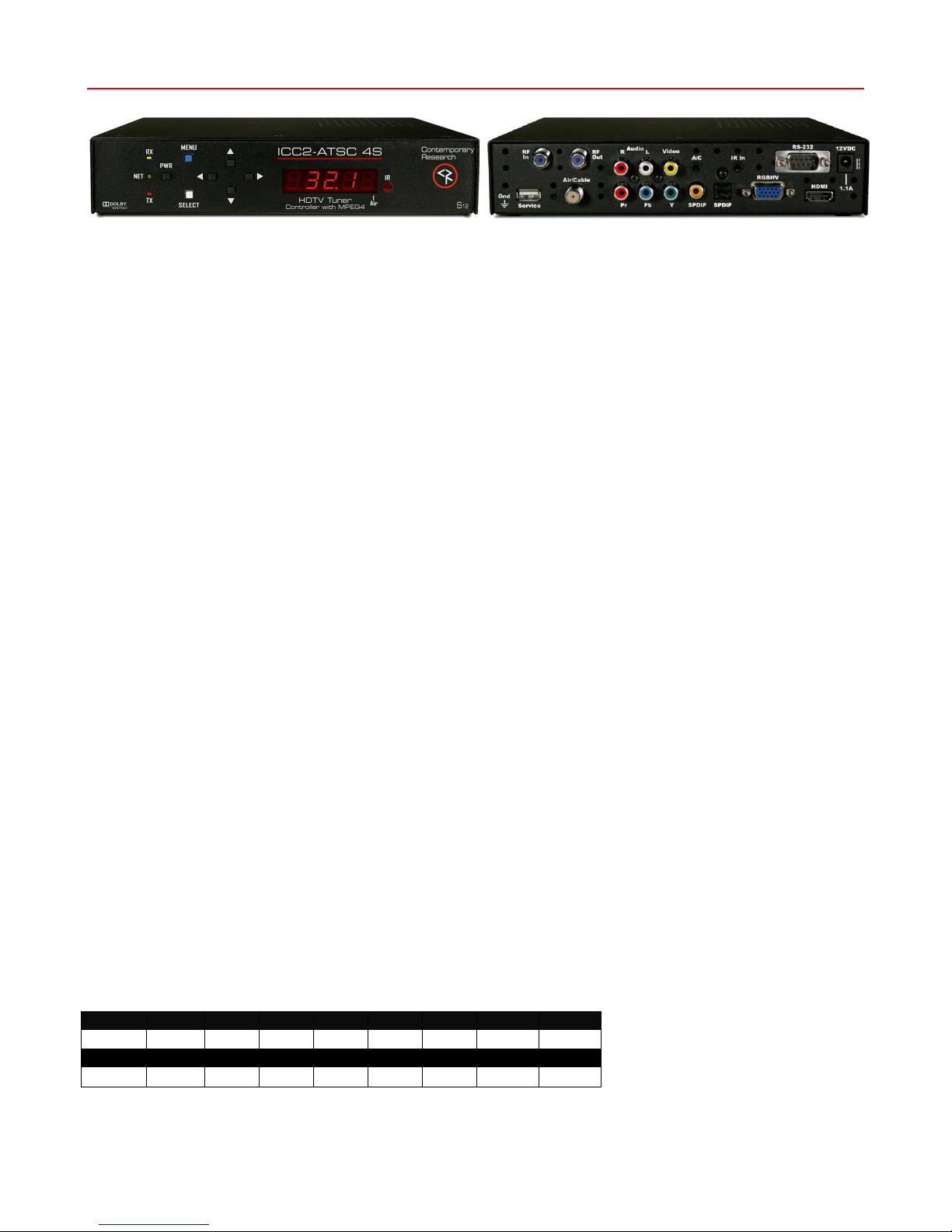
Front Panel............................................................................................................................................................24
Rear Panel.............................................................................................................................................................25
Tuning ..................................................................................................................................................................25
Includes ................................................................................................................................................................25
Options .................................................................................................................................................................25
Safety Instructions ..................................................................................................................................................... 26
Limited Warranty and Disclaimer .................................................................................................................................. 26

Contemporary Research 3 ICC2-ATSC 4S
Setup Guide
All instructions for the ICC2-ATSCS applies to the legacy ICC2-ATSC 4. Setup tools include:
•HD2-RC Remote Mode (accesses On-Screen Graphic Menus and special HD functions)
•IC-RC Remote Mode (accesses on-screen Text Menus)
•Front-Panel Setup
•ICC-Net commands from Display Express, iC Send software, or custom control system
The ICC2-ATSC 4S is designed to offer advanced analog/digital tuning, yet be compatible with existing iCC-Net systems.
IR Remote Operation
The optional HD2-RC IR Remote is designed for control and setup of ATSC-series HDTV tuners, and normally, the tuner will
respond to the remote in the same way as other ATSC-series tuners.
There is a special IC-RC mode that can be set from the front-panel menus. This will activate the on-screen text menus to
set the device address and control type, and a few other special functions. When the settings are done, the tuner can be
set back to normal HD2-RC operation.
Front-Panel Setup
The Front Panel modes are useful for setting tune mode, channel scan, HD output and resolution, switching between IC
and HD2 remote modes, and setting the device address and control type, and other options.
IC Send/ICC-Net Control
You’ll find the free IC Send program to be a great tool for system setup and testing, especially if the site is using the ICE-HE
Head End and your laptop is configured for the site’s network. You can also use a PC or laptop via RS-232 with the ICC-HE
Head End. Key functions include:
•On, Off and Tune commands to test operation to one or all ICC2-ATSC 4S units.
•IR Mode. Switch all tuners to IC or HD2 modes.
•Channel Setup. Use the T^ Command to force all units to scan channels, then use the XA and XD commands to
add and remove channels from the list. If you’re using RS-232 control at the head end, have an ICC2-ATSC 4 at
that location to check your setup.
•Tuner Setup. Use LM and TM commands to configure general tuner operation.
•Default Input. Use the ER command to set the default input.
•Control Type. Change RS-232 control type and baud rate
Device Address Settings
Use the front-panel setting 2 and 3 to set the address. Menu 3 sets the Zone address, and Menu 2 sets the individual
number in the zone. For example the system address for a controller is 257, set Menu 2 to 2.1 (1), and Menu 3 to 3.1
(Zone 1, which is address 256), 1 + 256 = 257 system address. The controller will act by itself when you send the unique
257 code, as a zone group when you send 256, or from address 4095 (All).
Zone
1
2
3
4
5
6
7
8
256
512
768
1024
1280
1536
1792
2048
Zone
9
10
11
12
13
14
15
2304
2560
2816
3072
3328
3584
3840

Contemporary Research 4 ICC2-ATSC 4S
FAQ
Tuning Cable
Channels
The 232-ATSC 4S will skip encrypted channels automatically when you activate a channel scan.
You can skip scanning analog channels by pressing Select after you start the scan.
Typically, the digital channels will not use the same Guide numbers as a cable box.
If you can’t select channels, make sure that the channels have been scanned.
RGB/Component
Video
Analog HD is output on either the RGBHV (VGA) or Component output. Use the front-panel
menu to select the desired output.
There can be “fluttery” lines at the top of the analog video –this is closed captioning data.
Go to the Overscan menu and increase the value.
HDMI
HDCP is always off –not required for non-encrypted programs
If a monitor has issues with current resolution, 1080p/60 works best for newer models.
Composite Video
Press the RATIO button on the IR remote to select the desired format for NTSC video
The onscreen menu also has Screen Format settings, generally only used when tuning an analog
channel.
Audio
Volume won’t affect digital audio in AC-3 or PCM modes, while PCM Variable supports level
control. If there is no audio, make sure the volume is all the way up (and not muted).
A “motorboat” sound means the source does not support AC-3, change to PCM.
IR Control
There can be interference from room fluorescent lights. Hold down SELECT on the remote.
Pressing 4 selects normal 38 KHz IR, pressing 9 selects 57 KHz IR.
Check the front-panel R Receive menu to see if it is turned on or off.
If there is significant IR interference, an IR-RXC Remote Sensor may be required, and cover the
front-panel IR sensor to reduce interference.
RF Network
When the tuner is connected to the RF network and an IC-HE series interface has been installed,
the NET LED on the front panel will blink once per second, confirming the unit is receiving the
“heartbeat” command. If the NET light does not flash, check the RF connection at the ICE-HE.
Control Codes
The tuner’s control type has been pre-set at the factory when shipped. Once you connect the
source with an RS-232 cable, the Power button should turn the monitor or projector on and off.
There should be a label on the unit that states the current control type, or:
•Use front-panel menu 50 to see or change the type
•Use the IC-RC mode text menu
•Send a T0 command to change the type
The control type sets the baud rate to a typical setting for the source, the rate can be changed
from the front-pane menu, or an R5 command over RF.
Device Address
If the tuner’s NET LED is flashing, but the TX LED does not flash when a command is sent from
Display Express or a custom control system –it is likely not at the correct address. If an All Zones
command (4095) is sent, and the unit responds –the address is incorrect.
Check the settings via the front panel menu, or enable the IC-RC mode to display the current
setting using an IR remote.

Contemporary Research 5 ICC2-ATSC 4S
RF Wiring Options
There are two ways to wire RF feeds to the ICC2-ATSC 4S.
Single RF Feed
Most applications will use a single RF feed, either Cable or Air (Antenna).
•Connect the RF feed to RF In on the top of the tuner. This allows the tuner to receive the iCC-Net control signal.
•Connect the included short RF cable from RF Out to the Air/Cable RF input.
Dual RF Feed
Other applications will use both Cable and Air (Antenna) feeds. The tuner can switch between both, maintaining separate
channels lists for each. You’ll need the optional RF-AB switch, which has a mini 3.5mm cable that connects to the A/C
control output on the back of the tuner. The placement of RF connections on the RF-AB is different than shown –the RF
ports above are arranged for clarity.
•Wire the Cable feed to the RF In input at the top of the back panel. Note that the Cable feed needs to go to RF In
so the tuner can receive the iCC-Net control channel.
•Connect the RF Out to the Cable input of the RF-AB.
•Connect the Antenna feed to the Air input of the RF-AB.
•Connect the included short RF cable to the RF-AB switch RF Out, then to the Air/Cable RF input on the tuner.
•Connect the 3.5mm mini plug to the A/C control output.

Contemporary Research 6 ICC2-ATSC 4S
Front Panel Setup
To Enter Front Panel Programming Mode:
1. Press and hold the Power button, then press the Volume Up (Right Arrow) button
2. Release all buttons, the ICC2-ATSC 4S will now be in the front-panel programming mode. The Air LED will flash,
indicating programming mode.
3. The first two digits show the mode, the second show the option.
4. Changes are saved in non-volatile memory as they are entered.
5. The Volume up/down buttons scroll through programming modes, forward and reverse.
6. The Channel up/down buttons scroll through possible options for each mode.
To Exit the Front Panel Mode, push and release the Power button.
Mode
0-9
Parameters
RF Tune
0.0
0=CATV (Default)
1=Off-Air
2=IRC
3=HRC
4=Cable Auto
Baud Rate
1.N
1 = 300 6 = 9600
2 = 600 7 = 19200
3 = 1200 8 = 38.4K
4 = 2400 9 = 57.6K
5 = 4800 10 = 115.2K
Unit Number
2.1
1-99 To enter a higher device number, use the On-Screen Menu on page 8
Zone Number
3.0
1-15 System device number is (Unit + (Zone * 256))
Panel Lockout
4.0
Reserved (performed by LM command)
Power-up Volume
5.0
5.N
Restore previous level (default)
1 –63 sets volume level
Firmware Version
6.68
Ex: Version 2.0 –Channel Up/Dwn to see HD firmware (3 digits). When at this menu:
Press and hold Channel Up, then Power to restore tuner to default settings
Press and hold Channel Up and Down, then Power to scan channels
Captions
10.0
10.1
Captioning off (default)
Captioning on
Caption Mode
11.1
11.2
11.3
11.4
11.X
1=Caption 1 (default)
2=Caption 2
3=Caption 3
4=Caption 4
5-8= Text 1-4 (rarely used)
Video Detect
12.3
No AV mute (fixed)
AV Status
13.0
No AV status (default)
Label Mode
14.2
Numeric (fixed)
IR Receive
15.9
0= Off, 9=Receive IR
Digital Captions
17.1
1-6, Default is 1
IR Remote
18.1
0=IC-RC
1=HD2-RC
Tune Control
19.0
0=Tune all channels
1= Only tune channels in List
Digital Audio
47.0
47.1
47.2
0=AC-3–Dolby 5.1
1=PCM (set to this for audio through HDMI)
2=PCM Variable (default)
HD Output
48.0
48.2
RGB (Default)
Component
HD Format
49.0
49.1
49.2
49.3
49.4
0=1080i (Default)
1=720p
2=480p
3=480i
4=1080p
Control Type
50.N
Current Control type. Refer to next page for a list of types. Use Up/Down to change.

Contemporary Research 7 ICC2-ATSC 4S
RS-232 Control Library
The ICC2-ATSC 4S includes a full library of make/model codes, noted by the Type number. The tuner is shipped pre-set to
the type required for the order. The integrator can change the types from the front panel or IC-RC mode with an IR
remote, or from a T0 command send to the tuner over RF.
Type
Make
Display
Baud
Notes
0
CR
9600
Test code
1
Sharp
Projector
9600
3
Sanyo
Projector
19.2K
PLC-WK2500
4
NEC
Monitor
9600
Legacy models with early input commands; not plasma
5
Olevia
Monitor
19.2K
323V –26 second power-up
6
Panasonic
Monitor
9600
9
Mitsubishi
Projector
9600
XD560U
10
Samsung EX
Monitor
9600
Ex-Link
11
Samsung
Monitor
9600
400CXn, 460CXn, ME40A, ME46A, ME55A, MD55B
14
NEC
TV
9600
E-series TVs (redundant, this series has onboard tuners)
22
Hitachi
Projector
19.2K
Hitachi CP-S317, CP-S318, CP-X327, CP-X328 , Christie projector
LW650, LW750, LS700, DWL951, DHD951, LWU501i, LWU504
24
Epson
Projector
9600
VP 595wi, 1925W Projector
27
Samsung
Monitor
9600
LCD 323T and 403T
28
Samsung
Plasma
9600
29
LG
Monitor
9600
M3201, M4201, 42PM1M
32
NEC
Plasma
9600
Odd Parity
33
Sharp
Monitor
9600
LC46LE820UN
44
Projection
Design
Projector
9600
45
Extron
Wall Panel
9600
Emulates buttons on Pole Vault wall panel
46
Sharp
Monitor
9600
PN-L702B, PN-V601
47
Sharp
Monitor
9600
LC70LE745U, same as 33, but slightly different input selects - Use
for all new Sharp monitors
48
NEC
Monitor
9600
M-,P-, V-, X- series monitors
49
Christie
Projector
19.2K
DHD800
50
NEC
Projector
9600
NP-M402H (NEC default is 38.4K, user needs to change baud on
projector)
51
Barco
Projector
115.2K
RLS-W12
54
LG
Monitor
9600
55
Christie 2
Projector
115.2K
DHD850 –different than DHD800
Input Selects
Inputs can be selected as well, using a 0-NNN channel command, or example 0-211 selects HDMI 1. Some makes will need a
0-200 command to return to the tuner channel, others will switch back to the tuner automatically. Some input number may
shift, depending on the model.
200=TV/Tuner
201=Video1
202=Video2
203=Video3
204=S-Video1
205=S-Video2
206=Component1
207=Component2
208=RGB1
209=RGB2
210=RGB3
211=HDMI1
212=HDMI2
213=HDMI3
214=HDMI4
215=HDMI5
220=Display Port DTV
221=Display Port PC
Input Command
You will need to specify the default input for the ICC1-ATSC 4S, so that the unit will return to the correct input. Use On-
screen menu, IC-Send or Display Express to send the EI command on page 17 to the tuner once it’s on the RF network.

Contemporary Research 8 ICC2-ATSC 4S
On-Screen Menus (IC-RC Mode)
The remaining installation steps use the IR remote and the built-in character generator of the ICC2-ATSC 4S.
1. Change the IR Remote mode in front-panel menu 18 to IC-RC (18.0). This will enable the character generator to
display the menus below.
2. Touch Menu, then 999, then Enter.
3. The text CR MENU> should appear on the screen.
4. Key in one of the commands shown below, then press Enter to activate.
5. Note that, in Menu mode, the Channel Down key acts as a backspace/delete key.
CR Menu Number
Function
Unit Setup
45678
Display firmware version
45679
Display the unit’s device #. At this point, you can use the Channel Down key as a Delete key,
then enter a new device # with the remote’s numeric keypad, then hit Enter to save the new
number.
45700
Display current make/model control type, listed on the previous page. You can use the
Channel Down key as a Delete key, then enter a new device # with the remote’s numeric
keypad, then hit Enter to save the new number. The setting will use the default baud rate,
which can be changed using front-panel menus.
45720
Set Display/Projector Input
Enter code 1-19. See page 15 in the ER section for input codes
45718
IR Remote Type –if you are done using the IC-RC mode, change this setting back to HD2-RC
operation.
0=IC-RC
1=HD2-RC
Special Menus
65478
Reset controller, similar to disconnecting power then restarting.
65487
Initialize to factory default settings: Power on, unlocked, display channel 11, channel ring set
to 4, 5, and 11, Group 0. Note that this command works even if TV power is off or control is
locked out.
65480
Enable constant Net transmit to the Head-End. This is used for measuring the signal strength
of the unit’s RF output. Press Enter to stop transmit or the unit will automatically stop after
50 seconds.
65481
Display DA transmitter frequency control voltage –should be 2000 - 3150.
65482
Display iCC-Net RF receive signal strength. Shows Net RX if receiving the
iC-HE’s “heartbeat” pulse once per second, !NET RX if not.
65483
Display DF transmitter frequency deviation –should be 245 - 300

Contemporary Research 9 ICC2-ATSC 4S
HD2-RC IR Remote
The HD2-RC IR Remote can be used to setup the tuner and for daily operation. The IC-RC remote will work as well, the
image below shows the function of the keys when the tuner is in the HD2-RC mode.
Power
Turns tuner on and off. Discrete on and off IR commands are available as
well.
Volume Control
Use the Vol+, Vol- and Mute buttons.
Channel Selection
The key change in digital tuning is the need to add a dash (-) and number
after the traditional channel number. Analog channels are accessed using XX-
0, digital channels using XX-1 (or -2, -3, etc).
Ch+, Ch- and PrevCh can be used to access and recall channels.
Menu Operation
Press Menu to access the on-screen menus.
•Use the directional Arrows, Select and Exit to navigate the menus.
•List displays the list of all channels, arrow keys add/remove
channels, set Favorite Channel list
•Exit steps backwards out of menus
•Enter selects menu choice
Special Functions
•CC steps through available closed-captioning options
•Audio selects audio and SAP modes
•Signal displays channel signal level
•Ratio steps through aspect ratios, options depend on channel and
output types
•Info launches on-screen information window
•A/C selects Air or Cable tuning
•Fav Displays list of favorite channels
•Guide displays on-screen Guide
Features of many of the Special Function commands depend on whether the
current channel is analog or digital.

Contemporary Research 10 ICC2-ATSC 4S
iCC-Net Control Protocol
Overview
Control for over 4000 TV Controllers is provided through an ICE-HE Head-End Network Controller or ICE-HE DXL Display
Control Center that inserts a micro control channel through RF coax. The ICE-HE receives control commands via RS-232
and Telnet, and the ICE-HE-DXL adds a USB port.
Each TV Controller is assigned a unique device number from 257 to 4094. The devices are organized into 16 zones of 255
devices to handle large-scale TV installations. All the devices in each zone will respond to a single “virtual device number”
—one device number that represents all devices in each zone. There is also a global device number, 4095, that will
command all devices in the system. This feature dramatically speeds up system operation and programming, because one
command can affect an entire group of devices—or all. To take advantages of this feature, review the section iCC-Net
Zones following this section.
In Display Express, we reserve the first group of devices, 1-255 (for which there is no Zone), for components in special
applications. Zones 1-15 are used for CR TV Controllers.
The RS-232 port can communicate from 300 to 115.2K baud. The factory default setting is 19.2K baud, 8 data bits, no
parity, and 1 stop bit. IP commands can be sent via Telnet to IP port 2728. The USB port is typically used to provide RS-
232 control from a PC with Display Express software.
Command String Structure
Characters in command strings are expressed in a combination of hex and ASCII characters. For clarity, the following
protocol examples use the following conventions, similar to AMX protocol, most other control systems would use Hex.
•Single-byte hex numbers are preceded by the ‘$’ symbol
•ASCII characters or strings are enclosed in single quotes
•Numbers not marked as hex or ASCII are a single decimal byte
•Parameters shown in < > brackets are single byte
•A series of multiple commands or parameters are set apart by [ ] brackets
•Commas separate the bytes, but are not part of the protocol
•Double quotes enclose the command string, but are not part of the protocol
Command format:
“$A5,<dh>,<dl>,<ncb>,<cmd1>,<parameter> [<cmdN>]"
$A5 Starts the command
<dh> The zone or high order byte of the device*
<dl> The unit or low order byte of the device (0 for global zone)
<ncb> The number of command bytes to follow, the (total bytes) shown after are simply reference
<cmd1> The first command byte
<parameter> Command parameters (not used by all commands)
[<cmdN>] Multiple commands can be concatenated, with byte count added to <ncb>
* iCC-Net devices are arranged with a zone mindset. For example, a command sent to Device 256, which triggers all the
units in Zone 1, would be expressed as $A5, 1, 0 (first zone, device zero). A command sent to 257 would be $A5, 1, 1
(first zone, device 1 in the zone). See iCC-Net Zones following this section.

Contemporary Research 11 ICC2-ATSC 4S
Writing Your Own Control Code
While most IC systems use our Display Express software to control displays, a growing number of integrators are writing
their own control applications, using AMX, Crestron, RTI, or other platforms. We encourage creative solutions, and are
happy to support those who take advantage of our protocol.
From our history of support activity, we are providing a few tips to help you on your way.
Device Numbers
iCC-Net devices are arranged with a zone structure, arranged in 15 groups of 256 devices. The first address in the group
represents the entire zone. For example, Zone 2’s group address is 512 (2*256). When a command is sent to 256, all
controllers in that group will respond as one. An ALL command is 4095 (15,255, F FF in Hex) –all controllers will respond.
All commands follow the same structure of:
•Attn = Hex A5
•Zone = 1-15 (hex 1-F)
•Unit = 1-255 (hex 1-FF)
•Bytes = Number of bytes that follow
•Command = 1 byte
•Parameters = 1 to 4 bytes
String Format
Every software application has a different denotation for handling hex, ASCII, and decimal formats. The examples in this
manual are in AMX format, which is understood by many in the control industry:
•Hex values begin with a dollar ($) symbol
•ASCII values are enclosed in single quotes
•Decimal values are shown as normal
If you plan on using a mixed-format structure for commands, convert the symbols to the types required by your software
application. For example, a Tune Channel 2-3 command to device 260 could be shown several ways:
•AMX Mixed Format = “$A5,1,4,5,’TH’,2,2,3”
•AMX Hex Format “$A5 $01 $04 $05 $54 $48 $02 $02 $03”
•Standard Hex (no denotation) = A5 01 04 05 54 48 02 02 03
•Crestron Hex Format = \0xA5\0x01\0x04\0x05\0x54\0x48\0x02\0x02\0x03
•RTI = Select port, Hex mode, enter A5 01 04 05 54 48 02 02 03 - note that when you go back to normal editing
mode, the app inserts an \x before each Hex character
Go to www.asciitable.com for a handy Decimal/ASCII/Hex conversion chart.

Contemporary Research 12 ICC2-ATSC 4S
iCC-Net Commands
Command
Description
Control
Power Off
P0
“$A5,<dh>,<dl>,2,’P0’ ” (6 bytes)
Power On
P1
“$A5,<dh>,<dl>,2,’P1’ ” (6 bytes)
Power Toggle
PT
“$A5,<dh>,<dl>,2,’PT’ ” (6 bytes)
Volume
VL
“$A5,<dh>,<dl>,3,’VL’,<vol level>” (7 bytes)
Sets TV volume level
0 = Mute
1 –63 = Minimum level (1) to maximum volume (63)
RS-232 Control
T0
“$A5,<dh>,<dl>,3, ‘T0’,<Control Type>” (7 bytes)
Change control type –see page 7
IR Remote
Q8=
“$A5,<dh>,<dl>,3, ‘Q8’,<IR Remote>” (7 bytes)
0=IC-RC
1=HD2-RC
Control Lock
LM
“$A5,<dh>,<dl>,3,'LM',<control>” (7 bytes)
Locks out front panel and IR remote control functions.
Bit 7 Selects IR remote control operation (0=enabled, 1=disabled)
Bit 6 Selects volume control operation (0=enabled, 1=disabled)
Bit 5 - 1 Always 0
Bit 0 Selects front panel buttons operation (0=enabled, 1=disabled)
Operating
Parameters
TM
“$A5,<dh>,<dl>,3,’TM’,<setting>” (7 bytes)
Sets up key functions in the unit
Bit 0 –Alpha channel labels
0=alpha labels off
1=alpha labels on
Bit 1 –Numeric channel labels,
0=num labels off
1=num labels on
Bit 2 –Channel up/down operation,
0=Tune Ring,
1=Send IR Keypad response
Bit 3-7 = 0
Control String
UX
"$A5,<dh>,<dl>,2+string length>,'UX'<string>" (variable bytes)
Sends an RS-232 string (ASCII, decimal, or hex) directly to the TV display.
Ex: "$A5,1,2,6,'UX, 'PON', 13" Sends PON, followed by carriage return (device 258)
Baud Rate
R5=
Set Baud Rate
1=300
2=600
3=1200
4-2400
5=4800
6=9600
7=19200
Inputs
LQ=
“$A5,<dh>,<dl>,3,’LQ’,<IR Code>” (7 bytes)
200=TV/Tuner 209=RGB 2
201=Video1 210=RGB3
202=Video2 211=HDMI1
203=Video3 212=HDMI2
204=S-Video1 213=HDMI3
205=S-Video2 214=HDMI4
206=Component1 215=HDMI5
207=Component2 220=DisplayPort DTV
208=RGB 1 221=DisplayPort PC

Contemporary Research 13 ICC2-ATSC 4S
Command
Description
Tuning
Tuning Format
S0=
“$A5,<dh>,<dl>,3,’S0’,<format>” (7 bytes)
0=CATV
1=Off-Air
2=IRC
3=HRC
4=Cable Auto
Tuning Style
H1=
NA
TC Response
H2=
NA –When the ICC2-ATSC 4 receives an analog channel command, it will attempt to tune the digital
equivalent first. If there is not a matching virtual channel, the unit will tune the analog channel.
Channel Up
TU
“$A5,<dh>,<dl>,2,’TU’ ” (6 bytes) – Tunes to next channel up
Channel Dwn
TD
“$A5,<dh>,<dl>,2,’TD’ ” (6 bytes) – Tunes to next channel down
Prev Channel
TP
“$A5,<dh>,<dl>,2,’TP’ ” (6 bytes) – Tunes to previous channel
Tune Analog Channel
TC
“$A5,<dh>,<dl>,3,’TC’, <channel>” (7 bytes) – Tunes to a specific channel 2-127
Scan Mode
D0=
“$A5,<dh>,<dl>,3, ‘D0’,<mode>” (7 bytes) – Scan Mode
Sets scan mode for digital and analog channels from the T^ or front panel scan command.
0= Scans for analog and digital channels scan (default)
1= Scans for digital only, deletes analog channels
2= Scans for digital only, keeps analog channels
3= Scans for analog only, deletes digital channels
4= Scans for analog only, keeps digital channels
Channel Scan
T^
“$A5,<dh>,<dl>,2,’T^’ ” (6 bytes) – Initiates channel scan
Tune HD Channel
TH=
Ex:
“$A5,<dh>,<dl>,5,’TH’,<H1>,<Major>,<Minor>” (9 bytes)
The tuner will ignore the first bit (H1), and tune the major (virtual) and minor channels. Values may
be in hex or decimal.
“$A5,1,4,5,’TH’,0,2,3” Device 260, virtual channel 2-3
The LQ command and TH 0-xxx (p7) can select inputs
Add Channel
XA=
Not applicable for the ICC2-ATSC 4
Delete Channel
XD=
Not applicable for the ICC2-ATSC 4
Tune Control
Q9=
Not applicable for the ICC2-ATSC 4
Captions
Q0=
“$A5,<dh>,<dl>,3, ‘Q0’,<on-off>” (7 bytes)
0=Captioning off (default)
1=Captioning on
Caption Mode
Q1=
“$A5,<dh>,<dl>,3, ‘Q1’,<mode>” (7 bytes)
1=Caption 1 (normal setting for most captioning)
2=Caption 2
3=Caption 3
4=Caption 4
5-8= Text 1-4 (rarely used)
Volume
V9=
Check with CR Support to see if Control Type supports external volume control
0=Tuner volume
1=External volume (such as video projector)

Contemporary Research 14 ICC2-ATSC 4S
Command
Description
Tuning
Input
EI
“$A5,<dh>,<dl>,3, ‘EI’,<Input>” (7 bytes)
Sets the input for controlled projector or display. See Input list in ER.
Input Ring
ER
“$A5,<dh>,<dl>,<ncb>,’ER’, [<input 1>, <input N>]” (variable bytes)
Sets a list of inputs that are cycled by the Input command on the IC-IR remote or KK command. Follow
the standard list of inputs below, check with CR Support on which are available for your make and
model of video display.
1 Video1 11 DVI/HDMI1 20 Display Port DTV
2 Video2 12 DVI/HDMI2 21 Display Port PC
3 Video3 13 DVI/HDMI3
4 S-Video1 14 DVI/HDMI4
5 S-Video2 15 DVI/HDMI5
6 Component1 16 TV
7 Component2 17 TV2
8 RGB1 18 1394
9 RGB2 19 Memory stick
10 RGB3/DTV
Ex: “$A5,<dh>,<dl>,6,’ER’, 1,4,8,11” sets ring to Inputs 1, 4, 8 and 11.
Text
Write Text
DM
“$A5,<dh>,<dl>,<ncb>,‘DM’, <start line>,<text color>,<text background color>, <screen
background>,<size and shadow>,<timeout>,<message bytes>” (variable bytes)
Clears current text, displays text message over video (default) or blank background. The built-in
character generator can accept up to 40 characters of text (including carriage returns), 28 characters
per line. Use a hex $0D or decimal 13 in the text as a carriage return, which will advance CG to the next
line, first space on the right.
Start Line - 1-9
Text Color - 1-7= White
Text Background Color –0-7=Transparent (no background)
Full screen background –0=normal insert over video
Size and Shadow –0-3=small text with drop shadow
Time-Out –0=15-second display, 1=persistent
Persistent text stays on screen until the next DM, or new Menu or channel.
Ex1: “$A5,<dh>,<dl>,10,‘DM’, 2,7,0,0,1,0,’TEST’ ” displays the word TEST on the second line, white text,
inserted over video, small size with drop shadow, and timing out after 15 seconds.
Ex2: “$A5,<dh>,<dl>,2,‘DM’ ” clears on-screen display, also clears persistent text
The ATSC uses white text and clear backgrounds when it receives a Text or Background Color
parameter between 1 and 7, and accepts values 0-3 for text size and shadow. This allows compatibility
with Smart TVs mixed in the same system that can display other colors and fonts.
Return
EB
“$A5,<dh>,<dl>,2,’EB’ ” (6 bytes)
Moves cursor down to the first column of the next row.
Text Timeout
DQ
“$A5,<dh>,<dl>,3,’DQ’, <time>” (7 bytes)
Sets screen timeout to specified time in seconds (1-254). If time is 0 or 255, any text on the screen will
persist indefinitely, or until cleared.

Contemporary Research 15 ICC2-ATSC 4S
HD2-RC Remote Emulation
You can also emulate IR commands sent from the CR HD2-RC Wireless Remote. If you are using the numeric keys to select a channel,
the user or program will need to follow the numeric command with an Enter.
.
KK=<key>
“$A5,<dh>,<dl>,3,'KK',<control>” (7 bytes)
* = Reserved for future
products/applications
0=*
1=*
2=*
3=*
4=*
5=*
6=*
7=*
8=*
9=Power (tog)
10=0
11=1
12=2
13=3
14=4
15=5
16=6
17=7
18=8
19=9
20=
21=Enter
22=Ch Up
23=Ch Dn
24=Vol Up
25=Vol Dn
26=Vol Mute (tog)
27=Power On
28=Power Off
29=Menu
63=Guide
80=Freeze
81=Signal
82=Ratio
85=Audio
88=Favorite
95=List
96=Add/Delete Channel
98=Air/Cable
99=Dash -
100=Info
101=Prev Chan
105=Menu
106=Cur Rt
107=Cur Lt
108=Cur Up
109=Cur Dn
110=Select
111=Exit
115=CC
141=Format 1080i
142=Format 720p
143=Format 480p
144=Format 480i
145=Format 1080p
149=Output RGB
151=Output YPbPr
153=Air
154=Cable
155=Aspect ratio pillar/letter box
156=Aspect ratio full/wide
157=Aspect ratio zoom
158=AC-3(Dolby 5.1)
159=PCM
160=PCM Variable
161=16:9
162=4:3

Contemporary Research 16 ICC2-ATSC 4S
iCC-Net Response
Response
Description
New Channel
T
“ ‘<’,<dh>,<dl>,2,'T',<new channel>" (6 bytes)
Sent in response to T? command.
IR Function
R
“ ‘<’,<dh>,<dl>,2,'F',<IR Function>" (6 bytes)
Sent when unit receives a new function command is pressed (1-8) or released (0) from the IR remote.
0 = Release
1 = Play
2 = Stop
3 = Pause
4 = Fast Forward
5 = Rewind
8 = Record
IR Key
K
“ ‘<’,<dh>,<dl>,2,'K',<IR Key>" (6 bytes)
Sent when unit receives a new key command is pressed (10-23) or released (0) from the IR remote.
0 = Release 102 = Timer
10 - 19 = Numeric keypad entry 0 –9 105 = Media Menu
21 = Enter106 = Cursor Right
22 = Channel Up 107 = Cursor Left
23 = Channel Down 108 = Cursor Up
29 = Menu 109 = Cursor Down
101 = Previous Channel 110 = Media Select
The 0 –9, Channel Up/Down functions are sent only if enabled in the TM command
(Bit 2 = 1). The Channel Up/Down responses will be sent if the Tune Ring contains no channels –see Ex2 in
the Tune Ring command section.
IR Menu
M
“ ‘<’,<dh>,<dl>,5,'M',<msh>, <msl>, <mph>, <mpl>" (9 bytes)
Sent when unit receives a new Menu command is pressed or released (0) from the IR remote. Menu
Selection high and low bytes are in <msh> and <msl>. Menu Parameter high and low bytes are in <mph> and
<mpl>.
A Menu command is initiated by pressing the Menu key, followed by a numeric entry, then the Enter or
Channel Up key. During the Menu process, the Channel Down key acts as a backspace or delete key.
Some selections that need only a single numeric entry and will have a parameter value of zero (0). Those keys
are 0, 8, 9, 18, 20, 30, 900, 911, and 912.
Menu selections that will prompt the user to enter a second parameter entry are:
1 = Select Media
2 = Password
3 = Chapter Search
4 = Frame Search
11 = Channel
21 = Page Zone
22 = Page Room
25 = Go
21 = Attach Zone
32 = Attach Room
Tip: The Menu entries are active even if the TV power is off.

Contemporary Research 17 ICC2-ATSC 4S
iCC-Net Zones, Units and Device Addresses
In the front-panel setup instructions, you set the Unit # (1-255), then the Zone # (1-15). This refers to the
iCC-Net address structure that includes device number 256 –4095 that is divided up into 15 Zones.
To simplify controlling large groups of devices, iCC-Net is divided into 15 zones of 255 devices. All the devices within each
zone can be controlled simultaneously by sending a command to a single virtual device number.
For example, noting the zone chart below, if we send a Power On command to device #256, all iCC-Net controllers in Zone
1 will turn off at the same time.
This is an immensely powerful feature, because most systems can only address one device at time. If you need to turn off
all 50 TV in a zone, you would need to send 50 commands. In addition to the hassles of creating multiple commands,
there would be a long delay between the first and last command. One command, instant response is easier.
The Zone number plus the Unit number equals the actual device address.
Zone
Device #
Unit
Total Device #
1
256
1-255
257-511
2
512
1-255
512-767
3
768
1-255
769-1023
4
1024
1-255
1025-1279
5
1280
1-255
1281-1535
6
1536
1-255
1537-1791
7
1792
1-255
1793-2047
8
2048
1-255
2049-2303
9
2304
1-255
2305-2559
10
2560
1-255
2561-2815
11
2816
1-255
2817-3071
12
3072
1-255
3073-3327
13
3328
1-255
3329-3583
14
3584
1-255
3585-3839
15
3840
1-255
3841-4094
All Zones
4095
Tip:While many applications can use just the Zone number, it’s a good practice to assign a unique Unit number to
each controller in the zone. This allows the system software to address individual controllers if necessary.

Contemporary Research 18 ICC2-ATSC 4S
System Map
One of the key tasks for iCC-Net integrators is to create a logical System Map, assigning device numbers to TV controllers
so they fall into physical zones useful to the client. The device mapping could be sorted by type or location; whichever
suits the application.
iCC-Net Zone
Zone
Room
Unit
Device
1
W 1st Floor
256
W151
1
257
W152
2
258
W153
3
259
W154
4
260
2
W 2nd Floor
512
W251
1
513
W252
2
514
W253
3
515
W254
4
516
3
E 1st Floor
768
E151
1
769
E152
2
770
E153
3
771
E154
4
772
4
E 2nd Floor
1024
E251
1
1025
E252
2
1024
E253
3
1025
E254
4
1026
5
Cafes
1280
G100
1
1281
G150
2
1282
G151
3
1283
6
Entrance
1536
TV 1
1
1537
TV 2
2
1538
7
Hallways
1792
W1
1
1793
W2
2
1794
E1
3
1795
E2
4
1796
8
Concession
2048
Lower
1
2049
Upper
2
2050
All Zones
All
4095

Contemporary Research 19 ICC2-ATSC 4S
On-Screen Menus
Main Menu
Selects sub-menus.
•Arrow keys highlight option
•Select (or Enter) chooses option
•Menu steps back or exits menus
•Exit exits all menus
•Some options are only available if you are currently tuned to an analog or digital
channel
Channel Menus
Sub-Menu for Channels offers options for:
•Channel Auto-Scan
•Favorite Channel Selection
•Add/Delete Channels
•Fine Tune (If tuned to an analog channel)
•Signal Strength Meter
Auto-Scan
Starts scan of analog and digital channels for:
•Air –looks for NTSC and ATSC channels
•Cable Auto –looks for analog and digital QAM cable channels, as well as all
frequency plans
•Cable STD - standard cable spacing
•Cable HRC –HRC cable spacing
•Cable IRC –IRC cable spacing
Tip:
Normally, use Auto. Most cable channels will be in standard frequencies. If all the channels
tune in STD but channels 5 and 6, scan for IRC. If few channels can be found, scan for HRC.
Favorite Channels
Menu is also displayed from the List command, selects channels advanced by the FAV
favorite channel command.
Use the Up, Down arrows to move through the list, press Select to add a channel to
Favorites.

Contemporary Research 20 ICC2-ATSC 4S
Channel Add/Delete
This menu can add or delete a channel accessed from Channel Up and Down.
You can tune to a channel you want to delete, then press Menu/Channel/Add-Delete.
Press Select to delete the channel. You can also keep the page on screen as you step
through channels, adding and deleting as desired. If the channel has a good signal, it will be
displayed in the background.
Note that HDTV channels are broadcast on UHF frequencies. The Add/Delete will show the
name of the digital channel, as well as the actual UHF channel used for broadcasting.
You can delete one of a digital channel’s sub-channels without affecting the others.
Signal Strength
This page also displays from the Signal remote command. The graphic shows the current
signal strength, and changes in real time. This allows you to monitor the strength of a
channel as you adjust the antenna for best reception.
Caption Menus
This menu accesses captioning features:
•On/Off –turn captions on/off –other options are not available if captions are off.
•Analog Mode - CC 1-4 and Text 1-4
•Digital Mode –Service 1-6
•Digital Font Options
•Size –Standard (15 pixels), Large (21 pixels), or Small (11 pixels)
•Style –1-6
•Color –8 shade of background, foreground and edge colors
•Opacity –foreground and background
•Edge –6 style options
Version displays current version of tuner firmware
V-Chip Settings Menus
Manages access to programming for US and Canadian standards.
The default PIN number for access is 0000 (four zeros).
This manual suits for next models
1
Table of contents
Other Contemporary Research Tuner manuals

Contemporary Research
Contemporary Research 232-MCT User manual

Contemporary Research
Contemporary Research 232-FMA Instructions and recipes

Contemporary Research
Contemporary Research 232-FMA User manual

Contemporary Research
Contemporary Research 232-ATSC 4K User manual

Contemporary Research
Contemporary Research ATSC-mini User manual

Contemporary Research
Contemporary Research ATSC-SDI 4 User manual

Contemporary Research
Contemporary Research IP IP-HDTV IP-HDTV User manual