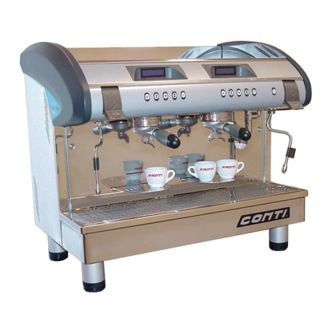
Conti TWIN STAR 2 Guide

TECHNICAL DOCUMENTATION
- 01/2005 - V1.11
SACOME, CONFIDENTIAL Document, it is forbidden to duplicate or communicate this document without previous authorization.


1INTRODUCTION : INSTRUCTIONS AND RECOMMENDATIONS ......................... 2
1.1 Installation instructions........................................................................................ 2
1.2 Warranty ............................................................................................................. 2
1.3 Safety instructions............................................................................................... 2
1.4 Power supply instructions ................................................................................... 2
2TECHNICAL FEATURES......................................................................................... 3
3INSTALLATION........................................................................................................ 4
4ACCESSORIES........................................................................................................ 4
5STARTING OPERATION ......................................................................................... 5
5.1 Bleeding of the coffee boilers.............................................................................. 5
5.2 Filling of the hot water & steam boiler ................................................................. 5
5.3 Next filling ........................................................................................................... 5
6DESCRIPTION OF OPERATING DEVICES............................................................. 6
6.1 Steam tap............................................................................................................ 6
6.2 Hot water tap....................................................................................................... 6
6.3 Filters .................................................................................................................. 6
6.4 Dummy filter........................................................................................................ 6
6.5 Filter- holders ...................................................................................................... 6
6.6 Cappuccinatore (option)...................................................................................... 6
6.7 Steam jet (option)................................................................................................ 6
6.8 Espresso tray ...................................................................................................... 6
6.9 Grinder fork ......................................................................................................... 6
6.10 Water hardness tester...................................................................................... 6
7FUNCTIONING & PROGRAMMING ........................................................................ 7
7.1 Automatic switching ON & OFF .......................................................................... 7
7.2 Programming ...................................................................................................... 8
7.3 Beverage preparation ......................................................................................... 9
7.4 Others functions................................................................................................ 12
7.5 Alarms............................................................................................................... 15
7.6 Heating of the boilers ........................................................................................ 18
7.7 Programming .................................................................................................... 18
8HOW TO MAKE A PEFECT ESPRESSO .............................................................. 29
9MAINTENANCE /SETTINGS.................................................................................. 29
9.1 Daily Maintenance ............................................................................................ 29
9.2 Weekly Maintenance......................................................................................... 29
9.3 Maintenance every 3 month.............................................................................. 29
9.4 Electronic pressure switch ................................................................................ 30
9.5 12 bar Security valve ........................................................................................ 30
9.6 Recommendation.............................................................................................. 30
9.7 Cleaning procedure for the decanteur............................................................... 31
10 DIMENSIONS ...................................................................................................... 33
11 ELECTRIC DESIGNATIONS............................................................................... 34
12 ELECTRIC DRAWING ........................................................................................ 35
12.1 CPU board ..................................................................................................... 35
12.2 Power circuit for “400 V 3NAC” & “230 V 1NAC” ........................................... 38
12.3 Power circuit for “230 V 3AC”........................................................................ 39
12.4 Relays box for “400 V 3NAC” & “230 V 1NAC” .............................................. 40
12.5 Relays box for “230 V 3AC” .......................................................................... 41
13 HYDRAULIC DRAWING ..................................................................................... 42
14 DECLARATION OF COMPLIANCE WITH INTERNATIONAL COMMUNITY
DIRECTIVES ................................................................................................................ 43
1

1 INTRODUCTION : instructions and recommendations
1.1 Installation instructions
- The installation must be carried out by a technician specifically trained by CONTI. The
manufacturer is not responsible for any damages caused due to incorrect installation or
use. The coffee machine must be installed on a solid furniture, supporting its weight
under any circumstances.
- It is necessary to make the machine level to obtain equal coffee portions.
1.2 Warranty
- The life span of the TWIN STAR 2 depends on the correct utilisation of the machine, the
daily cleaning and preventive maintenance.
-The non-respect of the daily cleaning and preventive maintenance would cancel
the contractual warranty.
1.3 Safety instructions
- The machine should not operate without supervision.
- The machine should only be used for its intended purpose.
- Only switch the machine on when the water shut-off valve is open.
- Only place empty cups on the cup warmer.
- Attention: coffee, hot water and steam can cause injuries.
- Never clean the machine with a high-pressure water jet.
- The hot parts of the machine, in particular the group and the cup warmer, can cause
burns. Gloves or a protecting cloth must be used when cleaning the hot parts.
- Gloves should be worn when removing and cleaning the basin to avoid injuries -
- The safety devices must be regularly checked and maintained (service engineer).
- Do not remove the cover panels (risk of electric shock).
- Do not cover the machine in operation to allow air circulation.
A regular and professional maintenance of the machine, the regular regeneration/refill of the
water softener and maintenance of the safety devices are compulsory.
1.4 Power supply instructions
- Never unplug or plug in when the main socket switch is on!
- The machine must be connected to a circuit breaker.
- The customer must provide an electrical installation complying with the requested
standards of the country where the machine is installed.
- The power socket must be protected against current defects.
- The terminal plug must earth the machine.
2

2 TECHNICAL FEATURES
MAIN WATER SUPPLY DRAIN ELECTRICAL SUPPLY
*Minimum inlet pressure 2,5 Bar
*Water connection pin 3/8"
(t-piece supplied)
*The water supply pipes must
resist to a constant pressure of 10
Bars
*Water hardness <7°f (5°c or 4°d)
*If the pressure of the main water.
supply is superior to 5bars a
regulator must be installed
*Without pressure
*Drain connection pin 1/2"
(t-piece supplied)
*The drain pipe must be lower
than the machine
400Vac - 50Hz
3 phases
or
230Vac - 50/60Hz
Single phase
UL et ULC
Single phase
230V - 60Hz
TYPE
HEATING POWER
TOTAL POWER
ELECTRICAL
CONSUMPTION
(Watt) (Watt) (Amps)
230Vac 400Vac
2 GROUPS 7700 8000 21 max 14
3 GROUPS 9300 9500 21 max 14
BOILER CAPACITY ( IN LITERS )
2 Groups 3 Groups
TOTAL Hot Water/steam boiler 20 20
Hot water volume 14 14
Steam volume 6 6
Coffee boiler volume 2 x 0.5 3 x 0.5
WEIGHT (kg)
EMPTY Weight
(Kg) In operation
2G 60 75
3G 70 85
3

3 INSTALLATION
- Check the installation parameters (see 2. TECHNICAL FEATURES):
. power supply,
. water supply
. water hardness,
. waste outlet,
. air ventilation
. leveling.
- If the pressure of the water supply is above 5 bars, a pressure reducer has to be installed to
adjust the pressure between 3 and 4 bars.
- If the level is not correct, adjust the leveling in turning the 4 screws of the aluminum feet:
remove the “CONTI” cover to access to the front feet and remove the side panels to access
to the rear feet. A perfect level is very important to obtain an equal volume in the cups.
- Carry out the electrical and hydraulic connections.
- Connect the water softener between the cut-off tap of main water supply and the machine.
- Connect the machine to the waste outlet.
- Make sure that the flexibles are not squeezed and that the radius of curvature is as large as
possible.
- The emptying must be slightly inclined, the emptying in a siphon is recommended to avoid
the ascent of bad smell.
Note:
Means for disconnection from the supply having a contact separation of at least 3 mm in all
poles shall be incorporated in the fixed wiring according to the wiring rules.
4 ACCESSORIES
- 1 filter holder 1-cup
- 1 filter holder 2-cups for each group
- 1 filter 1-cup
- 1 filter 2-cups for each group
- 1 cleaning filter
- 1 cleaning brush
- 1 water hardness tester
- 1 cup support (for MUG-version) for each group
- 1 filter holder fastening lug for MAZZER grinder
- 1 T-piece 3/8 for water supply.
4

Part to maintain
P
5 STARTING OPERATION
5.1 Bleeding of the coffee boilers
Before the startup and the electric connection, the
coffee groups boilers must be purged.
Unscrew the 2 higher screws of the control panel
and rock it forwards, remove the 4 screws located
above the cup warmer and remove this last one.
Open the general water supply’s tap then unscrew
slightly the screw “P”' located at the back of each
boiler coffee, screw up the screw “P” as soon as the
drip begins.
Maintain the rear part on the boiler in order to
avoid a rotation during this operation
Renew the operation on each coffee group.
As soon as the machine is operating, make a dozen
of coffees (empty, without coffee) on each group.
If the water does not come out from the group,
check the opening of the taps on the flowmeters.
5.2 Filling of the hot water & steam boiler
- Check if the steam levers “V” are closed (low position).
- Switch the machine on in pressing ON/OFF. The display lights up and the automatic filling
up of the steam boiler starts. The machine doesn't warm up.
- When water reaches the safety sensor, the automatic heating of the boilers (coffee and
steam boilers in same time) starts.
- The LEDs of the touch buttons will become lit when the required temperature is reached.
- Hot water and steam can be used when the steam gauge indicates 0.8 bar (the standard
functioning pressure is 1.5 bar).
On/off
Hot water
Hot water control tap "E"Steam lever "V" (2)
à levier
Steam wand (2)
Display
Filter holder
Manometer "M"
Cappuccinatore
5.3 Next filling
The TWIN STAR 2 will manage the automatic filling of the boilers as long hot water is drawn
(water level sensor maximum).
♦ STANDARD PRESSURE – PRESSURE GAUGE:
The steam boiler pressure has been adjusted in the factory between 1.3 and 1.5 bars in the red
area. An electronic pressure switch maintains the constant pressure and restricts the power
consumption to the minimum.
An overheating thermostat will interrupt the boiler heating as soon as the temperature is
increasing abnormally.
THE MACHINE IS READY FOR OPERATION.
5

6 DESCRIPTION OF OPERATING DEVICES
6.1 Steam tap
Two steam taps operating with levers “V” heat liquids or froth milk for cappuccino by injecting
steam.
The liquid container should be high enough. The steam wand nozzle should soak into the liquid
but not touch the bottom.
6.2 Hot water tap
The electric tap “E” is made to prepare hot water specialties (tea, grog...).
The hot water temperature can be adjusted thanks to a mixer system. The volume of hot water
can also be adjusted via the programming mode.
6.3 Filters
The machine is supplied with 1-cup and 2-cup filters. Always ensure that the filters are
unclogged and clean. To remove used coffee grounds from the filter, turn the filter holder
upside-down and lightly tap it on the edge of a wooden box.
6.4 Dummy filter
The machine is delivered with a dummy filter. This component is only used for the daily cleaning
of the coffee groups.
6.5 Filter- holders
Never take the filter-holder off when the unit is operating, firstly, ensure that the fluid has
stopped flowing from the filter-holder outlet.
Always leave the filter-holders on the machine with the filters filled with the coffee grounds of the
previous coffee in order to maintain the temperature of the filter-holders.
When the machine is not in use for an expended period of time, remove the filter-holders and
expel the used coffee grounds.
6.6 Cappuccinatore (option)
This device is equipped with a 2-position switch and allows to produce froth or hot milk
automatically in pushing the right button of the left group of the machine.
To maintain sanitation standards it is compulsory that the operator cleans this component every
2 hours to prevent the risk of stale milk clogging the tubes.
6.7 Steam jet (option)
This kit allows to heat a liquid automatically in programming the steam temperature. The
temperature sensor in the steam wand detects the temperature required and the steam stops
automatically.
6.8 Espresso tray
Supplied with all Mug versions, this device allows to place espresso cups in a higher position.
6.9 Grinder fork
This part is supplied with the machines to adapt the filter holders of the Twin Star 2 to the
Mazzer grinders.
6.10 Water hardness tester
Supplied with the machine to check the water hardness of the main water supply.
6

7 FUNCTIONING & PROGRAMMING
7.1 Automatic switching ON & OFF
7.1.1 The Twin Star is connected to the main electrical supply: :
When switching on, the machine is getting back to the same state when it was switched off.
During 5 seconds the display indicates:
Twin star 2
R
e
v. 1.11
7.1.2 The machine is switched off:
When the machine is switched off
All the LED’s are off, all the outlets are off.
All the functions are off except the programming of the main board.
The display indicates “OFF” and the time is shown on the display of the left group.
OFF HH:mm OFF OFF
All the led are off, all the outlets are off, all the functions are off except the programming of the
main board. The displays indicate "Off" and the time appears on the first group display.
7.1.3 The machine is switched on:
The displays are lit and indicate: “CONTI”, the current time and the name of each group.
CONTI HH:mm
Roaster name
CONTI
Roaster name
CONTI
Roaster name
The water supply solenoid valve is activated.
The water level regulation of the steam boiler is activated.
When the safety sensor is reached (probe SS in contact with water):
The security relay is activated.
When the level sensor is reached (sensor SN in contact with water):
The heating elements of all the boilers (coffee & steam) are heating.
When the required temperature of the coffee boiler is reached:
All the LED’s of the group are lit,
All the functions of the group are operating.
7.1.4 Automatic Switching On & Off:
The automatic switching on & off of the machine could be programmed for every day of the
week:
The main electrical supply must be switched on.
The timetable is programmed in advance.
A day off could be set.
The automatic switching on & off could be deactivated (see programming)
7

7.2 Programming
1 Cup
espresso
2 Cups
espresso
1 Cup
regular
coffee 2 Cups
regular
coffee
Cappuccino
(on left group)
Continous flow
(on the other groups)
LED
Hot water
dose
7.2.1 Programming of coffee measures ::
To get into the programming mode:
Insert and turn the programming key. The displays indicate
Water volume
Pro
g
rammin
g
Parameters
Pro
g
rammin
g
Parameters
Pro
g
rammin
g
Press the right push-button (CAPPU/CONT) of the group to program.
- Programming the left group will also program the other groups.
- Programming the other groups will program each group individually.
The LED of the selected push-button blinks: PROGRAMMING MODE
Start the programming within 5 seconds (otherwise the machine will get out of the
programming mode).
Select the measure to be programmed by pressing the relevant button:
- All the LEDs of the group will go off,
only the LED of the selected measure will remain alight.
- The LED of the button CONT/CAPPU blinks.
- The pump and the solenoid valve of the related group are activated.
- The water is flowing. Once the required measure is reached, press the button again to stop
the flow.
- The data is stored.
The PROGRAMMING MODE will remain for 5 seconds (the right LEDs are blinking).
Continue the same procedure for the other measures of the group.
NOTES:
During the PROGRAMMING MODE the LEDs of the already programmed push-buttons go off.
Each group could be programmed individually: press the continuous flow button on the right of
each group.
Maximum flow time of the coffee measures: 3 minutes.
8

Wait for 5 seconds to go out of the programming mode before making coffees.
During the programming of one group, the other groups do not work (including the hot water).
The data are stored even if the machine is switched off.
7.2.2 Programming of tea measure :
Insert and turn the programming key. The displays indicate:
Water volume
Pro
g
rammin
g
Parameters
Pro
g
rammin
g
Parameters
Pro
g
rammin
g
Press the push-button CAPPU.
The LED of the CAPPU button blinks: PROGRAMMING MODE.
Press the HOT WATER button to program: the hot water solenoid valve is activated.
When the hot water measure is reached, press the hot water button again to stop the flow.
The data is stored.
NOTES:
Maximum flow time of the hot water measure: 120 seconds.
Wait for 5 seconds to go out of the programming mode before starting the flow.
The data are stored even if the machine is switched off.
7.2.3 Programming of steam measures :
If the machine is fitted with this optional device the steam programming is available in the
PROGRAMMING MODE (“Bar” menu”) – see chapter 5.6. PROGRAMMING
7.3 Beverage preparation
7.3.1 Coffee delivery:
The machine has to be switched on and the security water level in the steam boiler reached
(sensor SS).
Machine switched on and no delivery: all the LEDs are lit.
Press the push-button to deliver the programmed coffee measure (each push-button could be
programmed with a different measure – see PROGRAMMING MODE).
To stop the coffee flow press one of the 5 push-buttons of the operating group (except the push-
button CAPPU of the left group)
Press the selected push-button:
- The pump and the solenoid valve of the group are activated.
- The LED of the selected button is lit, the other LEDs of the group are turned off.
- The LEDs of the other groups are lit, the “Cappuccino” LED is also lit.
The flowmeter detects the volume of water. When the programmed quantity is reached
- the flow stops automatically,
- the pump and the solenoid valve of the group are deactivated.
9

- the LEDs of the group are lit.
All the groups on the machine can be used at the same time.
If one of the groups has been deactivated in the Bar menu, all the LEDs of this group will stay off.
If the left group is deactivated, all the LEDs of this group stay off, only the LED of the cappuccino
is lit and still active.
The coffee will not flow, if
- Time Out of the heating element (coffee boiler - alarm on the display),
- Overheating of the coffee boiler heating element (alarm on the display),
- Time Out for steam boiler filling up,
- The security sensor is not reached (lack of water in steam boiler).
When the coffee is flowing, the display of the operating group shows (according to the selection):
2 Espresso
in Pro
g
ress
1 Long dose
in Pro
g
ress
Continuous dose
in Pro
g
ress
1 Espresso
in Pro
g
ress
2 Long doses
in Pro
g
ress
7.3.2 Coffee delivery:
This function allows to moisten the coffee grind before infusion (opening of the solenoid valve
time t1, deactivating time t2 and reopening).
The pre-infusion is set in the factory and can be modified and set different on each button of the
group – see programming.
7.3.3 Tea measure :
Machine turned on, no tea delivery: The tea LED will stay alight.
Press the tea push-button:
- The tea solenoid valve is activated and the hot water is flowing.
- The LED of the push-button is lit.
The TEA delivery can be programmed. When the programmed time is reached the TEA
solenoid valve is closed and the hot water flow stopped.
The flow can be stopped before the end of the program by pressing the TEA button again.
The TEA and COFFEE functions can be used in the same time.
During the hot water delivery the display of the left group shows:
Tea
in Pro
g
ress
When coffee & tea are delivered in the same time on the left group, the display will show the
information alternately.
When the programmed time is reached, the solenoid valve will close.
7.3.4 Tea with pump :
The anti-splash system of the hot water outlet can be adjusted using the pump and the tea
solenoid valve in the same time – see technical menu.
10

7.3.5 Hot & froth milk delivery :
This paragraph only concerns the machine fitted with the cappuccinatore (option 1).
The cappuccinatore is equipped with a 2-position button (located under the cappuccinatore, on
the front panel):
1st position: the steam solenoid valve is activated to heat up the milk when the CAPPU push-
button is pressed (5th button of the left group).
2nd position: the steam solenoid valve and an air valve are activated at the same time to froth
the milk when the CAPPU push-button is pressed.
Cappuccino delivery:
Prepare first the milk foam and then a double espresso.
Place the cup under the Cappuccinatore outlet.
Position 2 of the CAPPUCCINATORE
Press the 5th button of the left group, the CAPPU push button.
The delivery starts when the push-button is released: the solenoid valve will be activated.
The display of the left group shows:
Cappuccino
in Pro
g
ress
The LED of the CAPPU push-button will stay alight.
The measure is not programmed.
When the required amount of foam/milk is reached, press the CAPPU push-button again to
close the CAPPU solenoid valve.
NOTE:
A security Time Out will close automatically the CAPPU solenoid valve after 180 seconds if the
user forgets to press the button again.
Place the cup with the milk foam under the filter holder outlet.
Press the push-button 2 espresso to finish the cappuccino.
In case of simultaneous delivery on the left group of espresso, tea & steam, the display will show
the information alternately.
7.3.6 Automatic steam control system:
This paragraph only concerns the machines fitted with this optional device.
A sensor is fitted into the steam wand which allows to control the temperature of the liquid.
When the programmed temperature is reached, the steam delivery will be stopped automatically
– see programming mode.
The machine is turned on, the steam LED is lit.
Press the steam push-button:
The solenoid valve is activated and steam delivered,
the steam LED will stay alight.
The steam delivery could be stopped before the programmed temperature is reached in
pressing the steam button again.
11

If the required temperature is not reached within 60 seconds, the steam delivery will be stopped
automatically.
When steam is delivered, the display of the left group shows:
Steam
in Pro
g
ress
In case of simultaneous delivery on the left group of espresso, tea & steam, the display will show
the information alternately.
7.4 Others functions
7.4.1 Safety level of steam boiler :
The water level is controlled by the sensor SS.
The sensor (SS) is not activated when the machine is OFF.
When the machine is ON and if the sensor does not detect the presence of water within 1 sec:
an alarm is activated,
the machine will turn off automatically and the left display will show:
Steam boiler
empty
To suppress this alarm, the machine must be turned off and on again.
Remark: If the machine is turned on with the steam boiler empty, the automatic water filling will
start without activating the alarm.
If the boiler fails to fill, the filling Time Out (sensor SN) will activate the alarm.
7.4.2 Automatic filling up of the steam boiler: :
The water level of the steam boiler is controlled by the level sensor SN.
When the sensor does not detect the presence of water within the time T ON, the solenoid valve
of the water supply EE will be activated.
When the sensor detects the presence of water within the time T OFF, the solenoid valve of the
water supply EE will be deactivated.
Both times, T ON and T OFF can be adjusted in the programming mode.
While the steam boiler is filling up, the left display will show:
Filling up
In Pro
g
ress
The steam boiler can be filled up using the pump MP and the solenoid valve EE simultaneously -
see programming mode.
12

7.4.3 Cleaning function :
A cleaning cycle can be carried out independently on each group and at any time, otherwise
and after 500 coffee are produced on a group, the corresponding display will show:
Please Rinse
Insert a blind filter with a cleaning tablet into one of the filter holders and install it on the group
where the message is shown.
To start the cleaning cycle and suppress the message, press during 2 sec the 5th push-button
(CONT/CAPPU).
The pump and the group solenoid valve are 2 sec ON, 1 sec OFF, repetition 15 times.
During the cleaning cycle the display will indicate:
Washing
in Pro
g
ress
When the 15 times rinsing cycle are finished, the display will indicate:
Rinse
Remove the filter holders, and press the 5th push-button (CONT/CAPPU)
The rinsing cycle start. The pump and the group solenoid valve are 2 sec ON, 1 sec OFF,
repetition 15 times. During the Rinsing cycle the display will indicate:
Rinsing
in Progress
When the rinse cycle is finished, the display will return to the standard mode and the coffee
counter of the group will go back to zero.
Remarks:
- The group continues functioning during the rinse cycle.
- Re. The coffee counter: each push-button is worth 1 unit, the CAPPU button has no value.
- The cleaning cycle can be activated before a message appears on the display.
- While a group is being cleaned, the others groups will work normally.
- All groups can be cleaned at the same time.
- The cycle can be stopped by pressing one of the five push-buttons of the group.
13

7.4.4 "Coffee credit" :
This function enables coffee roasters to program the machine for a limited coffee delivery.
It can be activated and deactivated. The coffee roaster has access to the programming mode
with an allocated password.
The coffee roaster can program the number of coffee shots to deliver according to the quantity
of coffee beans sold.
A value is attributed to each push-button – value adjusted in the programming mode. The
programmed credit decreases as and when the coffee is delivered.
A credit running out information can be programmed with a message on the display to inform
the user about the quantity of coffees left to allow him to contact the roaster before the machine
will be blocked.
The displays show:
Coffee credit
Outrunnin
g
Coffee credit
Outrunnin
g
Coffee credit
Outrunnin
g
When the programmed quantity of coffee shots were delivered:
The coffee push-buttons are deactivated, the LEDs go off.
The CAPPU push-button is deactivated, the LED goes off.
Only hot water and steam can be drawn.
The displays show:
Coffee credit
Exhausted
Coffee credit
Exhausted
Coffee credit
Exhausted
7.4.5 DATA RESET:
This function allows to program the standard parameters again when they were lost.
Procedure:
- Turn off the main electrical supply (remove the plug) of the machine.
- Press simultaneously the left push-button of the left group and the tea push-button.
- Turn on the machine (while pressing both buttons).
When the LEDs of the ‘continuous’ push-buttons of all groups are blinking the data is
programmed.
Turn off the main electrical and then reconnect the machine again to return to the standard
functioning.
Remark: the following data will not be modified after the execution of this procedure:
_ Factory set parameters. _ Language.
_ Roaster set parameters. _ Tea/ hot water settings.
_ Counter of delivered shots. _ Roaster’s name.
_ Time. _ Passwords.
14

7.5 Alarms
7.5.1 Time-out filling of steam boiler filling:
If the filling of the steam boiler (sensor SN covered) exceeds the set time (see programming
mode), the filling is stopped.
The machine will turn off automatically and all the leds will blink. The left display will show:
Alarm
Filling up
To suppress this alarm switch on the machine (ON/OFF).
7.5.2 Error flowmeter:
When during a coffee cycle the pulsations of the flow meter are absent for more than 6 sec., the
LED of the pushed button will blink and the display of the group will indicate:
Flowmeter
Alarm
However, the functioning of the group will continue.
If the pulsations come back, the alarm will be deleted and the coffee cycle will finish.
If the absence of pulsation remains for 180 sec, the coffee delivery will be stopped and the
alarm suppressed.
7.5.3 Coffee boiler over-heating:
If the water temperature in a coffee boiler rises above 140°C / 284 °F:
- All the LEDs of the group will blink.
- The heating of the coffee boiler will be stopped.
- The push-buttons of the group will be deactivated.
- The display of the group will indicate:
Group Boiler
Temperature
The alarm will disappear when the temperature decreases 2°C under 140°C/ 284°F.
Remark : If this alarm affects the left group, the CAPPU function will not be deactivated.
7.5.4 Steam boiler over-heating:
Overheating thermostats monitors the maximum temperature allowed in the steam boiler and in
the coffee boiler . When the maximum temperature is reached the overheating thermostat will
deactivate the security relay, the auxiliary contact STR will open.
- The LEDs of the TEA and CAPPU push-buttons will blink
- The heating and push-buttons are deactivated
- The display of the left group will show:
Klixon
Opened
15

7.5.5 Time out coffee boiler heating:
If a coffee temperature sensor is disconnected, the same procedure as for the Overheating has
to be applied.
The display of the defective group will show:
Group Boiler
Heating
The alarm will be activated even if the group is deactivated.
To delete the alarm switch the machine off and on (ON/OFF).
7.5.6 Coffee temperature sensor disconnected :
If a coffee temperature sensor is disconnected, the same procedure as for the Overheating has
to be applied.
The display of the defective group will show:
Temp probe
disconnected
To remove this alarm, switch off then on the machine.
7.5.7 Steam control system temperature sensor disconnected :
If a steam control system temperature sensor is disconnected:
- The LED of the steam push-button will blink
- The display of the group will show:
steam probe
disconnected
The steam push-button is still functioning but the steam control system is deactivated. The
steam push-button must be pressed again to stop the steam delivery..
To remove this alarm, switch off then on the machine.
7.5.8 Regeneration of water softener :
When a certain quantity of water has been used the LED of the CAPPU push-button will blink
and the left display will show:
Filter
regeneration
The message informs the user to change the cartridge (Brita) or to insert salt into the water
softener but does not stop the delivery of products.
When the regeneration has been carried out, suppress the message as follows:
1/ Turn off the machine (button On/Off).
2/ Keep pressing the 3rd push-button of the left group and switch the machine on again.
3/ Turn on the machine (button On/Off).
16

The water counter is reset to 0.
All parameters can be set in the programming mode:
a) flow rate of the water supply solenoid valve EE ( cc/sec )
b) flow rate of the flow meters (ml )
c) water quantity of regeneration period.
7.5.9 Water level on tanker
If the following message appears:
Lack of water
It means that the "water level tanker" contact is open.
Pratically, the user has to place a bridge on this contact. (see electrical diagram CN10).
This contact was made for future application, sensor level on Kit solo tankers).
17

7.6 Heating of the boilers
The heating of the boilers is managed by the main board when the machine is switched on.
A relay card located at the rear right side supplies the heating elements as follows:
Boilers Probes Resistances
Steam Pressure switch RC1 + RC2 + RC3
Coffee Group 1 Sensor ST1 RCC1
Coffee Group 2 Sensor ST2 RCC2
Coffee Group 3 Sensor ST3 RCC3
7.6.1 Regulation terms :
_ Coffee boilers:
The temperature is regulated with a probe (NTC) installed on each coffee boiler (hysteresis of 1
°C)
When the temperature reaches the programmed T° the supply of the relay will stop
When the temperature is 1° C above the programmed T° the supply of the relay is going on
_ Steam boiler:
When the 2-bar pressure is detected by of the pressure switch, the contact of the pressure
switch will open and the relay will deactivate and stop heating. A time filter has been installed to
avoid constant backlashes of the relay which could damage its contact.
7.6.2 Management of the electrical consumption:
With voltage 400V 3NAC or 230V 3AC (power 0):
All heating elements can be heated in the same time.
The heating elements are supplied separately according to the above described temperature
regulation.
The maximum consumption of the machine can reach 14Amps per phase (3 group machine).
With voltage 230V 1NAC (power 1 or 2):
To reduce power consumption, the machine only heats 2 or 3 heating elements at the same time.
Priority is given to the coffee boilers but one of the three heating elements of the steam boiler can
be supplied continuously.
Order of priority: RCC1 (heating element coffee boiler GR 1)
RCC2 (heating element coffee boiler GR 2)
RCC3 (heating element coffee boiler GR 3)
RC1 (heating element 1 for steam boiler)
RC2 (heating element 2 for steam boiler)
RC3 (heating element 3 for steam boiler) : desactived in position :POWER 2
The steam boiler can be heated with 1, 2 or 3 heating elements depending on the heating of the
coffee boilers.
The power consumption is limited to 21 Amp (power 1) or 16 Amp (power 2).
(These parameters have been adjusted in the factory).
7.6.3 Desactivation of coffee groups:
The user can deactivate temporarily one or several groups to reduce the power consumption
(see programming, Bar menu ) .
The LEDs of the deactivated group are OFF,
The heating is deactivated,
Remark : the programmed data of the group (measures, temperature, etc.) remain stored.
7.7 Programming
18
Table of contents
Other Conti Commercial Food Equipment manuals
Popular Commercial Food Equipment manuals by other brands

saro
saro EPS 900 operating instructions

Vulcan-Hart
Vulcan-Hart E30TB Installation and operation manual

Lotus cooker
Lotus cooker CWK-94ET Instructions for installation and use

Apach
Apach BAKERY LINE P Series instruction manual

Tecfrigo
Tecfrigo SOMMELIER 402 PLUS installation guide

croydon
croydon FZM8 Assembly, Installation and Operation