Contigo 6601H User manual

Commercial Vehicle Productivity and Security
The 6600H/6601H is a versatile and economical GPS tracking beacon
designed for fleet management needs in all commercial vehicles. The
“H” designation in the model number is used to indicate beacons that
are hard-wired when installed in the vehicle.
Combined with our commercial mobile monitoring portal, subscribers
can manage and view the location of any or all vehicles in a fleet, run
a variety of valuable reports, and manage vehicle maintenance alerts.
Antenna Configuration
The Contigo 6600H/6601H comes with a combined GPS/Cell Network antenna
module. The 6600H uses an external antenna attached with FAKRA
connectors, while the 6601H is equipped with an internal antenna housed
within the beacon.
For either configuration, the antenna must be positioned in the vehicle so that
it has a clear signal path to as much of the sky as possible, without metal
obstruction. For internal antennas, the beacon itself must be positioned
properly for good signal reception.
External Antenna Installation (model 6600H only)
The following antenna models are supported for the 6600H:
Wedge Antenna –Part #: 655x-ANT-WEDGE
•Black plastic housing; 5.4 in (138mm) length; 1.25 in (32mm) width;
0.44 in (11.2mm) depth;
•Mounted with peel-and-stick adhesive patch.
Magnetic Weatherproof Antenna –Part #: 655x-ANT-WP-M
•Black plastic with silver magnetic metal base; 2.54 in (64.5mm)
diameter; 0.54 in (13.6mm) depth;
•Mounted on any exterior metal surface.
Drill-through Weatherproof Antenna –Part #: 655x-ANT-WP-DT
•Black plastic with silver metal base and rubber weather-seal
gasket; 2.54 in (64.5mm) diameter; 0.77 in (19.5mm) depth
(excluding screw post);
•Screw post mount for drill-through applications.
For best performance, the top of the antenna should face the sky
through the area of least signal blockage.
•If the installation is not required to be covert, an ideal location is
underneath the front windshield glass. For covert installations, an
ideal location is under the dashboard, as close to the front
windshield as possible.
Contigo 6600H/6601H Beacon
Kit Contents
› GPS Beacon device with SIM
› Combined GPS/Cell Network
›antenna (if required)
› Wiring harness
Tools and Supplies Required
›Wire cutters, wire strippers
› Voltmeter (multimeter)
› Soldering iron, solder
› Electrical tape
› Plastic cable ties
› Screw drivers, mounting screws
› Wrenches, sockets

•In a car, the antenna can be mounted under the rear window or in the trunk, under the rear deck, as
close to the rear window as possible.
Antenna Installation Notes
•Signals will penetrate upholstery, carpet, plastic dashboards, etc., but not metal
panels or brackets.
•Signals will penetrate window glass but not metallic tinted windows or painted
edges of windows.
•Radio antenna or defrost wires embedded in glass may degrade signals.

Beacon Installation Position
•Determine beacon installation position but do not fasten it in place until all wiring is complete.
•Determine the best location for the beacon –a strong flat surface that can be drilled to accommodate
the mounting holes is ideal. Any spot where the beacon can be fastened in place with plastic cable ties
is suitable.
•For the 6600H with an external antenna, under a seat is often a suitable location for beacon installation.
Be sure it is not close to any heat sources or areas that experience moisture or vibration. The beacon is
not waterproof or weatherproof and should always be installed in the passenger compartment of the
vehicle.
•The 6601H has an internal antenna contained within the beacon housing. It is therefore important that the
top face of the beacon (the side with the large label) is facing the sky with no metallic obstruction. These
models are ideally located under the dashboard, and the same guidelines for installing an external
antenna (described above) are applicable.
•Visibility of the indicator LEDs will be useful for testing and troubleshooting.
Connect Power and Ignition Sense
The power harness included in the installation kit contains 14 wires, 3 of which are bundled together. The bundle
contains the 8-30V constant Power (Red), Ground (Black), and Ignition Sense (White) wires.
Notes
•Connect the wiring harness to the power and ignition source, as well as any I/O sources (if used), before
attaching the harness to the beacon.
•If wiring harness wires need to be extended, use the same gauge wire and solder the extension wire on,
then insulate with heat shrink tubing or electrical tape.
•Ensure that no wires are routed near heat sources.
Power Connection Instructions
•Connect the Black (Ground) wire to battery negative or the vehicle chassis –this wire MUST be connected
first, before the power or ignition sense wires. Be sure the grounding screw is not painted or coated with
an insulating material.
•With the vehicle’s ignition turned off, use a multimeter to assist in finding a suitable, constant 8-30V power
connection point –directly to the vehicle’s battery may be best. Important note: The red (power) cable
is configured with an in-line 3-amp fuse. This fuse must be installed as close as possible to the primary
power source connection.
•Ensure that any wires in the wiring harness that are not to be connected do not come in contact with
power, ground, or any other voltage. Insulate them with electrical tape.

Ignition Sense Connection
•The ignition sense connection is mandatory. Failure to install the ignition sense correctly will result in
erroneous data being reported from the beacon.
•Find a source of 8-30V that is switched on and off with the ignition key in the run position (accessory
position is not acceptable). This connection should produce 8-30V when the vehicle ignition is ON and 0
Volts when the vehicle ignition is OFF. Connect the white (ignition sense) wire to this point. Voltage
transitions must occur instantly. Gradual or stepped transitions from one voltage to another may not be
detected.
Important Notices
The 6600H/6601H is designated to operate from 8 to 30 Volts DC. 8V is the minimum voltage at
which the device will operate reliably. The user is responsible for ensuring the voltage supplied to
the beacon remains in this voltage range to include transient voltage spikes and load dump
voltages. Failure to comply may damage the beacon. The current draw under normal operating
conditions is approximately 100mA at 12V.
The beacon should never be connected to the same power source as the vehicle Electronic
Control Module (ECM), as this may adversely affect the vehicle electronics.
Failure to use the proper 3-amp fuse or to install the fuse in the recommended location could
cause a vehicle fire hazard. The fuse provides overload protection for the power cable and the
beacon. The wiring installed between the fuse and primary vehicle power is not protected from
overheating if a short should occur.
Failure to install the ignition sense correctly will result in erroneous data being reported from the
beacon. This may result in false or incorrect reporting of vehicle starts, stops, ignition on and off.

Contigo 6600H/6601H Cable Connectors
20-pin Molex Connector - Pin Descriptions
Pin
Wire Color
Description
Pin
Wire Color
Description
1
Black
GND
11
White
Switch 2 input (+)
2
Yellow
Relay 2 output (-) [Buzzer Control]
12
CAN/J1939 Hi [not used]
3
Green
J1708- [not used]
13
Red/White
Switch 4 input (-)
4
Orange
J1708+ [not used]
14
CAN/J1939 Lo [not used]
5
Blue
Switch 3 input (-)
15
White (bundle)
Ignition input (+)
6
Gray
1-Wire data [Driver ID, Sensor]
16
Brown/White
Relay 1 output (-)
7
Cable ID [not used]
17
[not used]
8
Red (bundle)
Power input (+8 to +30v constant)
18
Green/Yellow
Switch 1 input (+)
9
[not used]
19
Purple
LED Control [Driver ID]
10
Black (bundle)
Ground
20
Brown
Analog input (0 –16v) [not used]

Auxiliary Input
•The auxiliary inputs can be used to detect and report the opening and/or closing of a circuit. There are
four auxiliary inputs available on the 6600H/6601H beacon models, as indicated in the wiring diagram on
the previous page. Note that a minimum voltage of 8V is required to trigger any input.
•Auxiliary inputs 1 and 2 are considered to be closed when connected to a vehicle power source and are
considered to be open when connected to ground or an open circuit. Auxiliary inputs 3 and 4 are
considered to be closed when connected to ground and are considered to be open when connected
to a vehicle power source or an open circuit.
•When using auxiliary inputs to measure the state of vehicle circuits, it is recommended that you use a relay
to control the input signal to the device.
Output
•Outputs can be used to remotely control vehicle functions such as door lock/unlock and starter
disable/enable. There are two outputs available on the Contigo 6600H/6601H beacon models, as
indicated in the wiring diagram on the previous page. Output 2 is reserved for the Buzzer output, while
Output 1 is configurable for general use.
•Output 1 can be configured via the web portal to interactively toggle an external circuit between open
and closed states, or to pulse the circuit to the closed state for either 1 or 3.2 seconds, then automatically
open the circuit.
•To close an external circuit, the 6600H/6601H output acts as a ground source (or what is referred to as a
current sink) to the external circuit. To open an external circuit, the output will be open. Since the output
can draw a maximum current of 150mA, it is recommended that you use the output to control a relay
and use the relay to manage the external circuit.
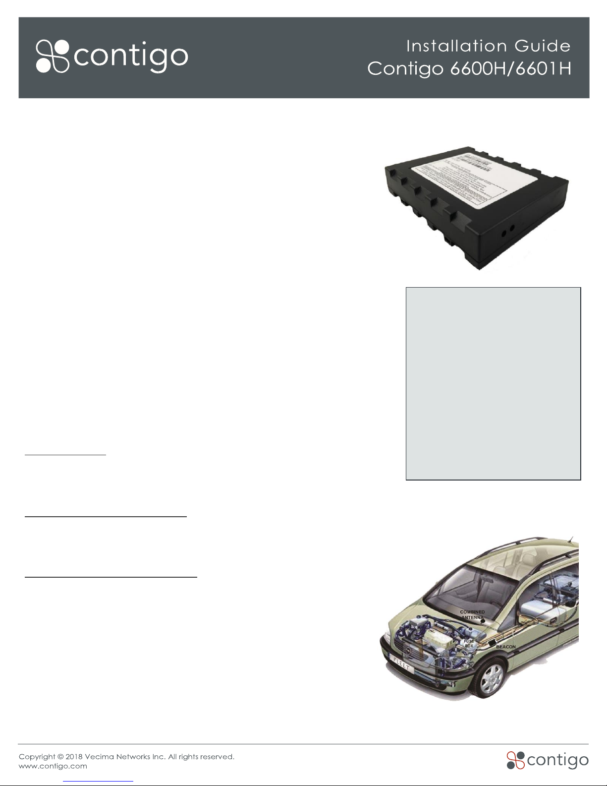
Connect and Mount Beacon
•For the 6600H beacon, connect the two antenna cables to the beacon using the corresponding FAKRA
connectors, ensuring a firm, positive connection is made.
•Attach the wiring harness to the beacon and ensure that the retaining clip snaps in place.
•Affix the beacon securely to the vehicle using the mounting slots found on either side of the case. If the
beacon is not securely mounted, it may report a false AWP, Start and Stop.
•If a suitable panel for affixing the beacon is not available, fastening the beacon to a bracket or wire
bundle with plastic cable ties is also adequate. Be sure to secure any loose or extra lengths of wire.
LED Indicators
The Contigo 6600H/6601H has two LEDs on the front of the device which indicate the current state.
•When the ignition is first turned on the Green indicator will show solid for about 30 seconds. After this initial
setup period, the Green LED will blink slowly (8 times in 10 seconds) when the Ignition is turned off, and
rapidly (25 times in 10 seconds) when the Ignition is turned on.
•The Red LED is used to indicate error conditions by flashing a 2-digit code. The first digit indicates the
general error type (1=hardware, 2=modem, 3=GPS, 4=end-to-end service) and the second digit indicates
a more specific error described in the table below. Note that if multiple error conditions exist, the Red LED
will cycle through all current error conditions.

Red LED Error Codes
1st Digit
2nd Digit
Error Condition
1
1
License key has expired. Please contact Contigo Support.
1
2
Low supply voltage. Ensure that the vehicle battery is supplying
adequate voltage. Contact Contigo Support if the error persists.
1
3
Data usage exceeded. Please contact Contigo Support.
2
1
Modem module fault. Please contact Contigo Support.
2
2
No SIM inserted. Please contact Contigo Support.
2
3
No cellular signal. *
2
4
Network not found. Please contact Contigo Support to verify the SIM
activation.
2
5
Last data session failed. *
2
6
GPRS not attached. Please verify beacon activation.
3
1
GPS module fault. Please contact Contigo Support.
3
2
GPS antenna fault. *
3
3
GPS not tracking any satellites. *
3
4
GPS no fix (<3 satellites). *
3
5
GPS has no time. *
4
2
Data transfer failed. *
* These issues may be caused by an incorrectly positioned beacon. If the device is connected properly and has
an unobstructed view of the sky, and the error persists, please contact Contigo Support.
Warnings and Known Issues
•It is important that the molex connector is installed fully into the beacon port, and that the device is firmly
attached to the vehicle. Excessive vibrations from a loose installation can cause incorrect results.
•The Contigo 6600H/6601H is not a waterproof or sealed device. Care must be taken to ensure the device
is kept away from water or any other liquids.
•The Contigo 6600H/6601H may be incompatible with certain models of vehicles. For more information
please contact your Contigo dealer.
This manual suits for next models
1
Table of contents
Other Contigo GPS manuals
Popular GPS manuals by other brands

Spylamp2
Spylamp2 Bicycle GPS Tracker instruction manual

Garmin
Garmin Foretrex 301 - Hiking GPS Receiver Quick start manual

Raymarine
Raymarine C120 operating guide

Neomatica
Neomatica ADM333 Operation manual

LoJack
LoJack EDGE M installation guide

Magellan
Magellan RoadMate 1200 - Automotive GPS Receiver User manual addendum