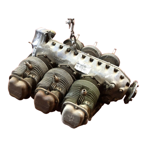
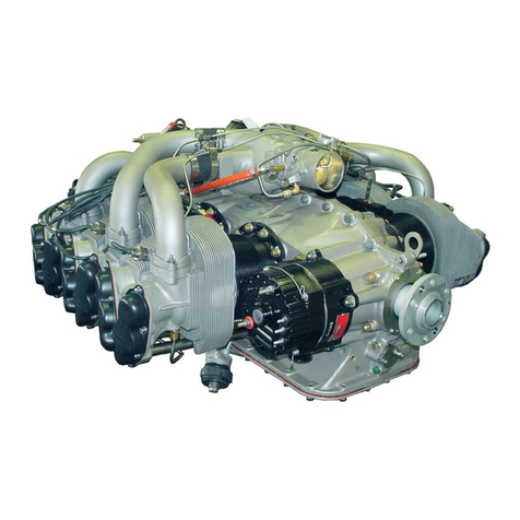
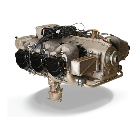
Continental Motors GTSIO-520 SERIES User manual

Publication X30079
©CONTINENTAL MOTORS, INC. AUGUST 2011
GTSIO-520-D
CONTINENTAL® AIRCRAFT ENGINE
OPERATOR’S
MANUAL
FAA APPROVED

A GTSIO-520-D Operator’s Manual
31 August 2011
Supersedure Notice
This manual revision replaces the front cover and list of effective pages for Publication Part
No. X30079, dated June 1974. Previous editions are obsolete upon release of this manual.
Effective Changes for this Manual
0.......................June 1974
1...............31 August 2011
List of Effective Pages
Document Title:GTSIO-520-D Operator’s Manual
Publication Number: X30079 InitialPublication Date:June1974
Page Change Page Change Page Change Page Change
Cover..............................1
A......................................1
i.......................................1
ii thru iv............................0
1 thru 40..........................0
Published and printed in the U.S.A. by Continental Motors, Inc.
Available exclusively from the publisher: P.O. Box 90, Mobile, AL 36601.
Copyright © 2011 Continental Motors, Inc. All rights reserved. This material may not be reprinted,
republished, broadcast, or otherwise altered without the publisher's written permission. This
manual is provided without express, statutory, or implied warranties. The publisher will not be held
liable for any damages caused by or alleged to be caused by use, misuse, abuse, or
misinterpretation of the contents. Content is subject to change without notice. Other products and
companies mentioned herein may be trademarks of the respective owners.

OPERATOR'S MANUAL
F,OR
GTSIO-520 SERIES
AIRCRAFT ENGINES
NOTICE
IN ORDER TO PROPERLY
USE
THIS ENGINE,
THE USER MUST COMPLY WITH
ALL
INSTRUC-
TIONS CONTAINED HEREIN.
FAILURE
TO
SO
COMPLY
WILL
BE
DEEMED MISUSE,
RELIEVING
THE ENGINE
MANUFACTURER
OF
ANY
RE-
SPONSIBILITY.
THIS
MANUAL
CONTAINS NO WARRANTIES,
EITHER
EXPRESS OR IMPLIED. THE PURPOSE
OF
THE
DATA
PRESENTED
IS
INSTRUCTION,
INFORMATION,
AND
SAFETY.
FORM NO. X30079
FAA
APPROVED
REVISED JUNE 1974
1

TABLE
OF
CONTENTS
FOREWORD PAGE
III
INTRODUCTION
.............................
1
DESIGN FEATURES . .
..
. . . . . . .
..
. . . . .
.. ..
..
. 1
1. General
...............................
1
2. Tabulated
Data
.........................
5
3.
Oil System
.....
'.
. . . . . . . . . . . . . . . . . . . . . . . 9
4.
Turbocharger..
. . . . . . . . . . . . . . . . . . . . . . . . . 11
5. Induction System
.......................
12
6. Ignition System
.........................
14
7. Fuel System
.........
. . . . . . . . . . . . . . . . . .
14
OBERATING
INSTRUCTIONS.....
..
. . . . . . . . . . . . 15
1. Before Starting
.........................
15
2. Starting. . . . . . . . . . . . . . . . . . . . . . . . . . . . . . . . . 16
3.
Warm Up .
..
. . . . . .
..
. . . . . .
..
. . . . . . . . . . . . 17
4. Take-Off & Climb
.......................
20
5.
Cruise.....................
. . . . . . . . . . . . 21
6. Descending and
Landing.
. . . . . . . . . . . . . . . . . . 21
7. Stopping Engine
.........................
22
TROUBLE SHOOTING . . . . . . . . . . . . . . . . . . . . . . . . . 22
. Trouble Shooting Chart
.......................
23
INSPECTION AND MAINTENANCE
.............
30
1. General
...............................
30
2. Daily Inspection
.........................
30
3.
50-Hour
Inspection
.....................
31
4.
100-Hour
Inspection
.................
, . . . 32
FIG.
1.
2.
3.
4.
5.
6.
7.
8.
LIST
OF
ILLUSTRATIONS
Sea Level Performance Curve
..............
.
Fuel
Flow
V
s.
Brake Horsepower
..........
.
Altitude Performance Curves
..............
.
Schematic
of
Lubrication System
..........
.
Turbocharger Sectional View
..............
.
Induction
System
....................
,
..
Schematic
of
Differental Pressure Tester
Idle
Adjustment
Points
..................
.
11
PAGE
3
3
4
10
12
13
33
38

FOREWORD
This
booklet
is
intended
to
serve pilots
and
maintenance
mechanics
as
a
pocket
size guide
to
operation
and
maintenance
requirements.
Subjects are
limited
to
engine
operation
and
inspection
normally·
carried
out
on
engines
installed
in aircraft
of
the
personal
and
executive
transport
types.
No
effort
is
made herein
to
describe
extensive
repair
work
or
overhaul.
For
such
instructions,
refer
to
the
applicable overhaul manual. Careful observation
of
operating
limits
and
compliance
with
recommended
inspection
procedures
herein
will
result
in
greater engine reliability.
world
wide use
of
Continental
® engines
in
personal aircraft has
led
to
an extensive
factory
approved
distributor
network.·
This
system
receives
the
constant
attention
of
our
Service
Department
with
the
aim
of
bringing spare parts,
repair
facilities
and
technical
information
to
the
aircraft
operator.
These distributors,
together
with
their
dealers,
bring
Teledyne
Continental
Motors
approved
spare
parts
and
service as close as
the
nearest
airport.
Continental
distributors
are regularly
supplied
with
Service Bulletins,
which
are available
for
study
by
engine owners
and
other
interested
parties. These
bulletins
may
also
be
obtained
on
an
annual
subscription basis
for
a
nominal
fee.
Subscription
order
forms are
available
from
authorized
distributors.
The
extent
of
this service organization,
and
the
demands
which
it
has
placed
on
our
Service
Department
personnel, have
made
it
impossible
to
communicate
directly
with
all individuals
in
regard
to
service
matters.
It
is
suggested
that
all
technical
questions, orders
and
reports
can
best
and
most
quickly
be
handled
by
your
nearest
authorized
distributor
and
that
you
should
become
acquainted
with
that
organization.
There
you
will
find
a sincere
interest
in
helping
you
get
the
best
service
from
your
Continental
engine.
No engine leaves
our
factory
until
it
has passed a rigid
operational
test
and
inspection.
Each
engine,
therefore,
is
believed
to
be free
of
defects.
If
any
Continental
engine
or
part
is
suspected
of
failure
or
does
not
perform
properly,
advise
your
nearest
authorized
distributor
giving
model
and
serial
number,
hours
operated,
and
complete
details.
Do
not
attempt
repalrs
without
proper
authorization
if
engine
is
within
warranty.
111


CONTINENTAL MODEL GTSIO-520 ENGINE
INTRODUCTION
The Continental model GTSIO-520-D and
Hare
6-cylinder,
fuel-injected, turbocharged, geared engines rated at 375
HP
at
3400
RPM. These air cooled engines have a wet sump oil system, dual
magnetos and continuous-flow injection system. An exhaust driven
turbocharger provides a full supply
of
intake air
as
the
airplane
climbs away from sea level and enters rarified air
at
altitudes.
Turbocharging provides a means for maintaining take-off power from
sea level
to
altitudes up
to
16,000 feet. The fuel injection system
supplies metered fuel
to
the
individual cylinders through injector
nozzles
to
assure
the
proper fuel-air ratio for desired performance at
all altitudes.
DESIGN FEATURES
1. GENERAL
The engines have overhead valves, air cooled, horizontally opposed
cylinders with 5.25 inch bore, 4.00 inch stroke, 520 cubic inch
displacement, and a compression ratio
of
7.5:1. The cylinders have
down-directed exhaust outlets. The propeller flange has six bolt
holes, two dowel pins and a center pilot extension provided for
attaching
the
propeller. The propeller drive shaft gear
is
driven
by
a
reduction gear, which in
turn
is
driven
by
the
crankshaft through a
splined shaft. Provisions are made in the pilot extension for the
hydraulic propeller control oil which
is
supplied internally from the
governor pad. The crankshaft
is
also equipped with pendulum
type
torsional damper weights. The engines have removable
type
hydraulic
tappets. Positive rotation
is
provided for the exhaust valves
by
the
use
of
rotators. Tappets, push rod ends and rocker arm bearings are
lubricated
by
the engine main oil pressure system.
1

~----------------~----~--~~--~~-=~--~~~==~~~----~---~
The engines are furnished with a scavenge
pump
to
return
engine oil
'II
from
the
turbocharger. A directdrive 24 volt, 50 amp alternator and
a direct cranking starter are furnished with
the
engines. . J
The turbocharger, furnished with
the
engines
must
be suitably
mounted
to
the
airframe in accordance with Continental
Specifications.
The
turbocharger has a dual scroll feature
to
provide
turbo-bleed air for cabin pressurization in addition
to
the
engine air
requirements.
The induction system includes an intercooler
to
provide for cooler
intake air from
the
turbocharger.
A variable pressure controller,
mounted
integrally
with
the
throttle
and bleed air housing,
is
cam operated through
the
throttle
linkage
and will control compressor discharge pressure according
to
cam
positioning.
The relatively high power delivered
by
these engines, per
pound
of
weight,
is
achieved
by
utilization
of
carefully selected high strength
materials,
by
improvements in design calculated
to
make
the
optimum
use ,of these high quality materials, and
by
very close
control
of
critical dimensions, surface finishes, heat
treatment
and
hardening processes. Careful work has produced more rugged engines
than
could be built
by
less exacting methods. However, no
amount
of
ruggedness built
into
an engine will enable it
to
withstand serious
mistreatment. Overheating, neglect, and inferior fuels and lubricants
will seriously affect engine performance, particularly when
the
specific power rating
is
high and each
part
must
be free
to
function
properly in order
to
withstand
the
imposed loads with minimum
wear. These considerations are mentioned here in order
to
emphasize
the necessity
of
using
the
manufacturer's recommended gasoline and
oil and
the
importance
of
keeping
the
fuel, oil and air filters clean.
The octane rating
of
engine fuel should be
as
specified in the
tabulated data.
2


2. TABULATED DATA
Manufacturer
Model
Type Certificate Number
Cylinders
Arrangement
Compression Ratio
Firing Order
Head Temperature -Max. Allowable
Recommended Cruise
Number
Numbering (accessory end toward
propeller end):
Right Side
Left Side
Bore (inches)
Stroke (inches)
Piston Displa<;:ement (cubic in.)
Brake Horsepower
Teledyne Continental
Motors
GTSIO-520-D & H
E7CE
Individual cylinders
horizontally opposed
7.5:1
1-4-5-2-3-6
460°F.
*
380°F.*
6
1-3-5
2-4-6
5.250
4.000
520
Rated Maximum Continuous Operation 375
Rated
Maximum Take-off 375
Rated Maximum
for
Cruising 282
Crankshaft Speed -RPM
Rated
Maximum Continuous Operation 3400
Rated Maximum Take-Off 3400
Recommended Maximum for Cruisng
2900
Recommended for Idling 600
* Indicates temperature measured
by
bayonet
type
thermocouple
in tapped opening
at
bottom
of
cylinder head.
5

--
---
-----------------~---
Prop Gear Reduction
Intake Manifold Pressure (Inches Hg.)
Maximum
at
Sea Level
Maximum
at
Critical Altitude
Induction System
Critical Altitude (feet
at
standard
atmospheric conditions)
Minimum Fuel Octane Rating
Fuel Control System
Fuel Consumption Rate (gal/hr)
Maximum Continuous Operation
Normal Cruise 60%
MC
Power,
Best Power
Normal Cruise 60%
MC
Power,
Best Economy
Oil Specification
Above
40°F
Below
40°F.
Below
40°F.
Oil Pressure
Minimum Idle (psi) t
Cruising Range (psi)
Oil Sump Capacity (U.S. Quarts)
* Optional per customers specification.
6
.67:1
39.5
39.5
Turbocharged
16,000
100/130
(Aviation Grade)
Continental Continuous
Flow Injector
.43.3
19.0
17.3
Continental MHS-24
SAE No. 50
SAE No. 30
10W30 (Opt.)
10
30
to
60
-
13*

Oil Level (Minimum for Operation)
Oil Consumption
(lb/BHP/hr.
max.
at
rated
power and RPM)
Oil Temperature Limits
Minimum for Take-off
Maximum Allowable
Recommended Cruising
Ignition Timing (Compression
stroke, breaker opens)
Right Magneto, degrees BTC
Left
Magneto, degrees BTC
**
.008
75°F.
240°F.
170°F.
**Minimum oil level for satisfactory oil cooling IS indicated
by
"LOW" mark
on
oil level gauge.
ACCESSORIES
Magneto(2)
Spark Plugs
Fuel Injector Pump
Turbocharger
Alternator
Voltage Regulator
Starter
MANUFACTURERS
Scintilla
See Service
Bulletin M68-4
Airesearch
Delco-Remy
Delco-Remy
Delco-Remy
7
MODEL
Left
Mag. S6LN-201
Right Mag. S6LN-206
See Parts Catalog
CMC
No. 633274-1
CMC
No.
632590
CMC
No.
631656
CMC
No.
627841

ACCESSORIES DRIVE RATIOS
TO
CRANKSHAFT
ACCESSORY DRIVE ROTATION (VIEWING
DRIVE PAD)
Magneto (2)
Fuel Injector Pump
Tachometer Drive
Alternator
Starter
Propeller Governor
Accy. Drives (2)
DIMENSIONS
Length (including turbocharger)
Width
Height
DETAIL WEIGHTS
a.
Basic Engine -includes lubrication
system accessory drives, starter
adapter, intake system, mounting
brackets, cylinders, six pendulum
type
dampers and a viscous damper.
Turbocharger
Spark Plugs (12)
Magnetos (2)
Ignition Assembly (all weather)
Variable Controller
Intercooler
Oil Cooler
Basic Engine Weight (dry)
8
CW
CCW
CW
CW
CCW
CW
CCW
RATIO
1.5:1
1:1
.5:1
3:1
32:1
.809:1
1.14:1
64.25 inches
34.04 inches
26.78 inches
482.29Ibs.
34.38Ibs.
2.70Ibs.
11.25Ibs.
2.75Ibs.
2.00Ibs.
5.50Ibs.
9.50Ibs.
550.37Ibs.

b. Basic Engine with Accessories
Basic Engine
Starter
Alternator
Tachometer Drive
Total Weight
of
Basic Engine and Accessories
3.
OIL SYSTEM (FIG. 4)
550.37Ibs.
16.00 lbs.
10.75 lbs.
1.381bs.
578.50 lbs.
The engine
is.
lubricated
by
a forced-feed system (Fig. 4). A
thermostatically controlled oil cooler maintains oil temperatures
normally
at
170 -180°F. Warm oil circulates continuously through
warm-up passages in
the
coolers,
to
prevent oil congealing when
operating in low temperatures. The capacity
of
the
oil sump
is
designed
so
the
quantity
of
oil available
is
sufficient
to
lubricate
the
engine
at
any nose-up or nose-down attitude.
It
is
impossible
to
uncover
the
oil pick-up line, which would result in low oil pressure, if
the
level in
the
sump
is
maintained at
the
recommended level shown
on
the
engine level oil gauge rod. Accessible oil sump drain plugs are
provided for use in changing oil
at
the recommended intervals.
The main oil pressure pump picks up oil from
the
sump and
discharges
it
through a passage
to
the
oil filter and oil cooler, and
to
the
engine oil galleries and bearings. Each cylinder wall and piston
is
additionally lubricated
by
individual oil squirt nozzles which direct a
continuous oil stream at
the
piston inner dome. Oil
is
returned
to
the
sump through drain holes. A filter by-pass valve
is
incorporated in
the
filter housing
to
by-pass oil in
the
event
the
filter becomes
clogged. Another passage in
the
filter housing
is
machined
to
accommodate a pressure control valve which regulates
the
pressure in
the
engine main oil galleries
..
Excess incoming oil
is
returned
to
the
sump. The oil cooler system includes a temperature control valve
to
automatically regulate oil temperature within specified limits. When
the
oil temperature becomes high enough
to
require cooling,
the
temperature valve expands and blocks
the
by-pass opening so
that
oil
flows through
the
cooler.
9

10

Engine oil
is
used
to
lubricate
the
turbocharger. This oil returns
to
the
sump after passing through a vapor separator and an engine
driven scavenge oil pump.
Engine oil is introduced
to
the
propeller governor through a passage
in
the
engine crankshaft, and
is
returned
to
the
sump through
passages in
the
crankcase.
4. TURBOCHARGER
A turbocharger
is
an exhaust gas driven compressor, or air pump,
which provides compressed air
to
the
engine intake manifold.
Turbocharged engines provide increased altitude performance more
economically
than
engines equipped with conventional gear driven
superchargers.
They
are lighter and have less moving parts
than
their
conventional counterparts, which provides optimum performance
over a longer period. The turbocharger
is
composed
of
a turbine
wheel, compressor wheel, turbine housing and a compressor housing.
The turbine wheel, compressor wheel and interconnecting drive shaft
comprise one complete assembly and
the
only moving
part
in
the
turbocharger. The thrust bearing and two journal
type
main bearings
are pressure lubricated
with
filtered oil supplied from
the
engine oil
system.
Engine exhaust gases enter
the
turbocharger through a flanged
connection, flow around
the
turbine housing and are forced radially
inward toward
the
turbine wheel (Fig. 5). A
portion
of
the
exhaust
gas energy
is
thus converted into kinetic energy which acts
upon
and
drives
the
turbine wheel. The turbine wheel, in turn, drives
the
compressor wheel which is basically a centrifugal blower, or air
pump, which produces air under pressure
to
the
air intake manifold.
The spent exhaust gases are
then
dumped through
the
exhaust
outlet
of
the
turbine housing. Combustion air
is
drawn into
the
center
of
the
compressor wheel; and flows outward through a diffuser section
and into
the
compressor housing. Air
is
forced
out
of
the
compressor
housing through a tangential
outlet
and enters
the
intake manifold.
11

COMPRESSOR
HOUSING
AIR
INLET
COMPRESSED
AIR
DISCHARGE EXHAUST
INLET
MAIN
DRIVE
HOUSING
TURBINE
WHEEL
EXHAUST
DISCHARGE
Figure
5.
Turbocharger Sectional View
The
degree
of
turbocharging
is
varied
by
means
of
a variable pressure
controller, which
is
cam
actuated
through
the
throttle
linkage and
will
control
compressor discharge pressure
between
31.5"
(Hg.) and
42.5"
(Hg.) depending
upon
cam positioning.
The
variable controller
is
mounted
integrally
with
the
throttle
and bleed air housing.
5.
INDUCTION SYSTEM (FIG. 6)
The
turbocharger supplies
intake
air
to
the
induction
system and
supplies
the
necessary
combustion
air
when
it
is
needed
most,
i.e.,
on
take-off, climb and during flight
at
high altitude where
the
air
is
less
dense
than
at
sea level.
The
turbocharger has
the
dual
scroll feature
to
provide turbo-bleed
air
for
cabin pressurization in addition
to
the
engine requirements.
The
turbo-bleed air
is
provided
through
a sonic venturi which limits
the
bleed air
to
approximately
six
pounds
of
air per
minute
at
sonic
flow.
The
engine
induction
system includes an intercooler capable
of
40%
effectivity
with
a static cooling air pressure
drop
across
the
cooler
of
6"
(H2
0)
pressure.
12

"""'
'..N
VARIABLE
SETTING
ABSOLUTE PRESSURE
,CONTROLLER
I
I
I
I
I TO CABIN
Figure 6. Induction System
~
LEGEND
=
..
RAM AIR
¢=>
AIR
<::=~
EXHAUST
GAS
-HYDRAULIC
OIL
COMPRESSOR
TURBINE

6. IGNITION SYSTEM
High voltage
current
is generated and distributed
to
the
upper
right
and lower left spark plugs
by
a magneto
mounted
on
the
front
side
of
the
right crankcase accessory pad.
The
magneto
on
the
left
crankcase pad, in addition
to
supplying high voltage
current
to
the
upper left and lower right spark plugs,
is
also equipped with a double
breaker.
The
double breaker magneto serves a dual purpose. When
cranking
the
engine
the
retard
breaker
is
in effect, causing a shower
of
high voltage sparks
to
start-the engine. As
the
engine
is
started and
the
cranking
motor
is
disengaged
the
retard breaker
is
no
longer
transmitting spark and
the
engine
is
running
on
the
advance breakers
from
both
magnetos. Spark
is
transmitted
to
the
spark plug
through
high tension cables which pass through flexible, braided, shielded
conduit assemblies.
7. FUEL SYSTEM
The
fuel injection system
is
of
the
multi-nozzle continuous flow
type
which controls fuel flow
to
match
engine air flow.
Any
change in air
throttle
position, engine speed,
or
a combination
of
both,
causes
changes in fuel flow in correct relation
to
engine air flow. A manual
mixture
control and a pressure gauge indicating
metered
fuel flow are
provided for precise leaning
at
any combination
of
altitude and
power settings. As fuel flow
is
directly
proportioned
to
the
metered
fuel pressure, settings can
be
predetermined and fuel consumption
can
be
accurately predicted.
The
continuous flow system permits
the
use
of
a typical
rotary
vane
pump
with
integral relief valve in place
of
a much more complex and
expensive plunger
type
pump.
The
relief valve maintains
maximum
fuel flow
under
full power conditions.
The
fuel
pump
also
incorporates a variable orifice and a centrifugal
rotor
for
separation
of
vapor formed between
the
tank
and engine
at
high altitudes.
14
l
I
I
This manual suits for next models
2
Table of contents
Other Continental Motors Engine manuals

Continental Motors
Continental Motors TSIO-360-F User manual

Continental Motors
Continental Motors O-200-D User manual

Continental Motors
Continental Motors TSIOL-550-C User manual

Continental Motors
Continental Motors N56 Troubleshooting guide

Continental Motors
Continental Motors R688-46 User manual

Continental Motors
Continental Motors GO-300-A User manual

Continental Motors
Continental Motors TSI0L-550-C User manual

Continental Motors
Continental Motors TSIO-520-BE User manual

Continental Motors
Continental Motors O-470-B User manual

Continental Motors
Continental Motors C-125 User manual