Jäger Z80-M530.14 S5 User manual

Manual
Z80-M530.14 S5
High Frequency Spindle
Manual tool change

Item no. 10205032, Revision 002 ( 36 )
Identification of HF spindle
Spindle type
Pmax S6-60% S1-100%
Item no. .... Serial no.
Rated rotation speed
Serial no.
Item no.
Performance data
Spindle type
As we always ensure that our HF spindles are at the cutting edge of techno-
logical development, we reserve the right to make technical modifications
and variations from the exact design described in the manual.
The text in this manual has been compiled with the utmost care. However, Al-
fred Jäger GmbH cannot assume any legal responsibility or liability of any
kind for incorrect information and any consequences thereof.
Translations and reproductions – including of extracts – are prohibited with-
out the express written approval of Alfred Jäger GmbH.

Item no. 10205032, Revision 00 3 ( 36 )
Contents:
Translation of the original manual
1 Preliminary information 4
1.1 Purpose of the manual.......................................................4
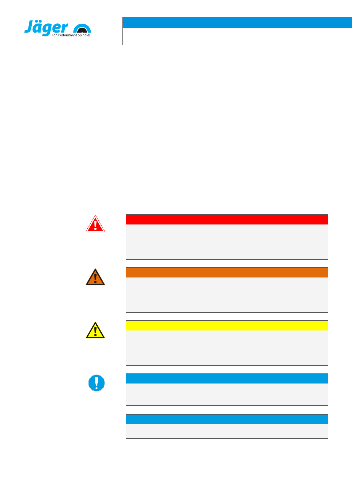
1.2 Explanation of symbols used........................................... 4
2 Transport and packaging 5
2.1 Scope of supply of HF spindle.........................................5
2.1.1 Optional accessories..............................................5
2.1.2 Documentation supplied.....................................5
2.2 Packaging of HF spindle.................................................... 6
3 Designated use 6
3.1 Permissible types of machining...................................... 6
3.2 Permissible materials..........................................................6
4 Safety instructions 7
4.1 Safe working.......................................................................... 8
4.2 Shutdown of HF spindle.................................................... 9
4.3 Installation and maintenance.......................................... 9
4.4 Modification and repair ..................................................... 9
4.5 Improper operation ............................................................9
5 Technical description 10
5.1 Connections of HF spindle .............................................10
5.2 Electrical connection ........................................................11
5.3 Cooling ..................................................................................11
5.4 Sealing air .............................................................................11
6 Technical Specifications 12
6.1 Dimensions ..........................................................................13
6.2 Technical data sheet (KL7003 , AC-Motor)................14
6.2.1 Performance Diagram........................................ 15
6.3 Wiring diagram...................................................................16
6.4 Motor protection PTC 160°C..........................................17
6.5 Speed sensor (digital differential magneto resistor)
..................................................................................................18
6.6 Air-borne noise emissions ..............................................18
7 Operating location 19
8 Installation 20
8.1 Installing the HF spindle..................................................20
8.2 Diameter of media supply line......................................21
8.3 Cooling water......................................................................21
8.3.1 Quality of cooling water.................................... 21
8.3.2 Setting the cooling.............................................. 21
8.4 Compressed air....................................................................22
8.4.1 Air purity classes (ISO 8573-1)..........................22
8.4.2 Setting the sealing air .........................................22
9 Commissioning 23
9.1 Running-in schedule..........................................................23
9.2 Daily start-up ........................................................................24
9.3 Shutdown signal .................................................................24
9.4 Commissioning after storage .........................................24
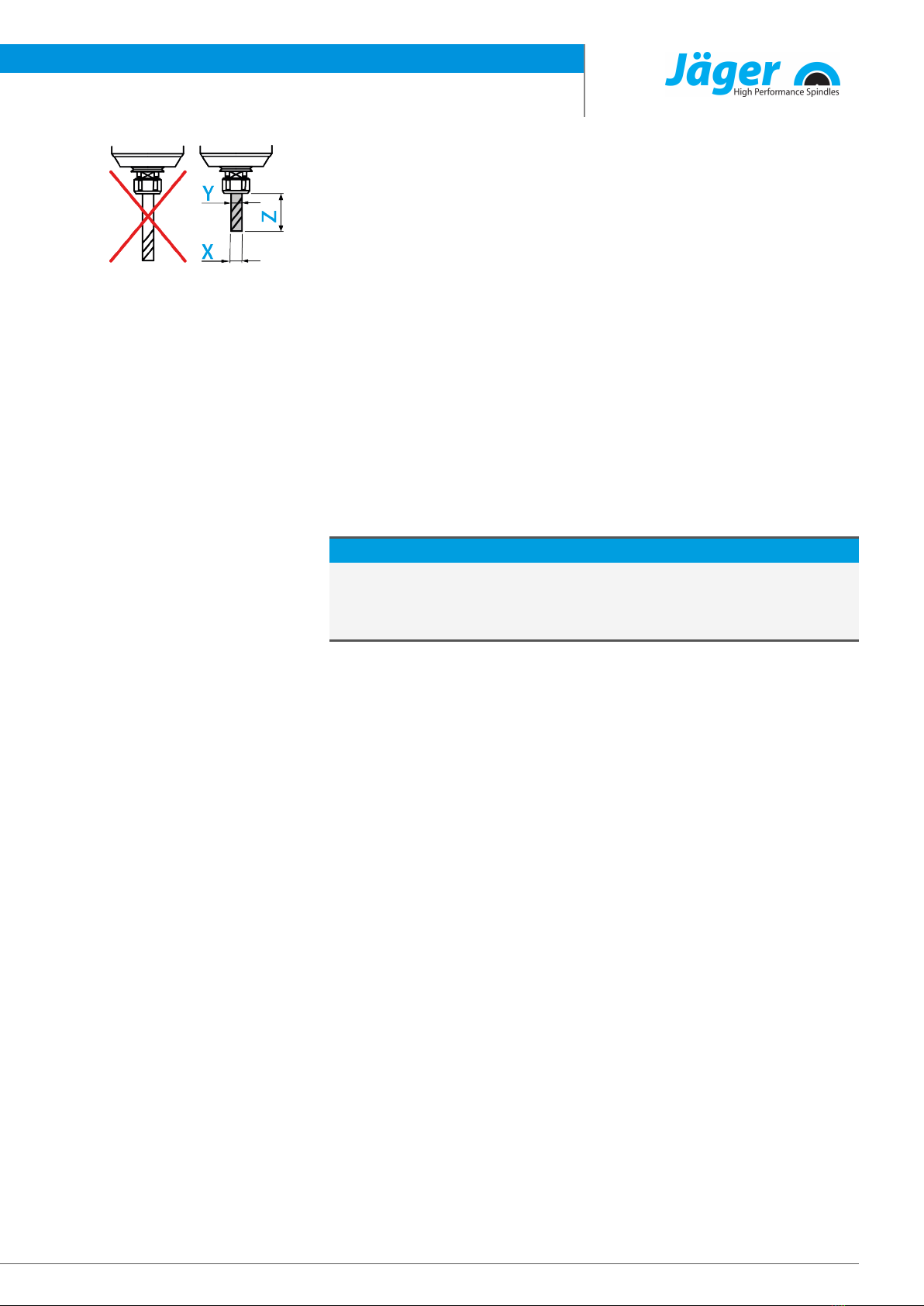
10 Tool change 25
10.1 manual tool change...........................................................25
10.1.1 Maximum tightening torques..........................26
11 Tools for high speed cutting 27
12 Maintenance 28
12.1 Ball bearings .........................................................................28
12.2 Daily cleaning.......................................................................28
12.2.1 Before commencing work .................................28
12.2.2 With every tool change ......................................29
12.3 In the case of storage.........................................................29
12.4 Monthly maintenance.......................................................29
12.5 Long periods of storage ...................................................29
12.6 Maximum storage time.....................................................29
13 Dismantling 30
13.1 Disposal and environmental protection ....................30
14 Service and repairs 30
14.1 Service partners...................................................................30
14.2 Malfunctions.........................................................................31
15 Warranty 34
16 Declaration of Incorporation 35

Preliminary information
Item no. 10205032, Revision 004 ( 36 )
1 Preliminary information
The high frequency spindle (HF spindle) is a high quality precision tool for
high speed machining.
1.1 Purpose of the manual
The manual is an important component of the HF spindle.
ÜStore the manual carefully.
ÜMake the manual available to all persons who work with the HF spindle.
ÜRead the documentation supplied in full.
ÜBefore carrying out any work, read the corresponding section of the man-
ual carefully again.
1.2 Explanation of symbols used
To enable quick classification of information, this manual uses visual aids in
the form of symbols and text markings.
Notes are marked with a signal word and a colored box:
DANGER
Dangerous situation!
Results in serious injury or death.
uMeasure to avert the danger.
WARNING
Dangerous situation!
May result in serious injury or death.
uMeasure to avert the danger.
CAUTION
Dangerous situation!
May result in minor to moderate injury.
uMeasure to avert the danger.
Note
May result in material damage. This warning symbol is not a warning for per-
sonal injury.
Tip
Tips indicate useful information for users.

Transport and packaging
Item no. 10205032, Revision 00 5 ( 36 )
2 Transport and packaging
Avoid strong vibrations or impacts during transportation, as these could dam-
age the ball bearings of the HF spindle.
ÜAny damage reduces the accuracy of the HF spindle.
ÜAny damage restricts the functionality of the HF spindle.
ÜAny damage shortens the service life of the HF spindle.
2.1 Scope of supply of HF spindle
The following parts are supplied with the HF spindle:
qHigh Frequency Spindle
qFelt cleaning taper
qJaw wrench
qHook wrench
qTransport packaging
ÜCheck the high frequency spindle for completeness upon delivery.
2.1.1 Optional accessories
Available on request:
qSpindle holder
qFrequency converter
qChiller
qCollet
qCollet grease
qHose connections
qMotor cable
qFurther accessories on request.
Only approved accessories have been tested for operational safety and func-
tionality.
ÜDo not use any other accessories – this may invalidate any warranty claims
and compensation claims for damages.
ÜIf the spindle holder is to be produced in-house, it is essential to contact
Alfred Jäger GmbH before starting production to request the tolerances
and production plan for the spindle holder.
2.1.2 Documentation supplied
The documents listed below are supplied with the HF spindle:
qManual
qThe declaration of incorporation is part of the manual.
qInspection protocol
ÜCheck that the documentation supplied is complete when the spindle is
delivered. If necessary, request a new copy.

Designated use
Item no. 10205032, Revision 006 ( 36 )
2.2 Packaging of HF spindle
All transport packaging materials can be recycled in appropriate disposal facil-
ities.
3 Designated use
The HF spindle is an “incomplete machine” in accordance with the Machinery
Directive and cannot perform any function independently. The HF spindle can
only be operated in conjunction with a machine tool and a frequency con-
verter.
3.1 Permissible types of machining
The HF spindle has been developed only for the following types of machining.
qCutting
qDrilling
qEngraving
qGrinding
ÜContact Alfred Jäger GmbH if other types of machining are required.
3.2 Permissible materials
The HF spindle has been developed only for the following materials.
qMetals (such as alloys, cast metals etc.)
qSintered materials
qPlastics
qWood
qGraphite
qStone (marble, etc.)
qPaper and cardboard
qCircuit boards
qGlass and ceramic
ÜContact Alfred Jäger GmbH if other materials are to be machined.

Safety instructions
Item no. 10205032, Revision 00 7 ( 36 )
4 Safety instructions
The high frequency spindle is a state of the art product and is safe to operate.
However, the HF spindle may pose a risk in the following cases:
qIf it is installed by untrained personnel.
qIf it is used incorrectly.
qIf it is not used in accordance with its intended use.
The high frequency spindle may only be installed, commissioned, and main-
tained by specialist personnel.
Definition: Specialist personnel are persons who are familiar with the assem-
bly, installation, commissioning, and operation of the product and have the
relevant qualifications for their area of activity. The operator must closely con-
trol the responsibility, training, and monitoring of these personnel.
DANGER: Due to explosion.
HF spindles are not approved for use in areas at risk of explosion. Use in such
areas may result in explosions.
uDo not use the HF spindle in potentially explosive atmospheres.
DANGER: Due to flying parts.
The HF spindle operates at high speeds and may therefore be flung away by
these.
uOperate the HF spindle only if it is installed in the machine or system in a
fixed manner.
Note: Adhere to the limit values.
uObserve the limit values specified in the technical data.
Note: Take account of the machine.
uObserve the manual of the machine in which the HF spindle is installed.
uObserve all safety instructions specified by the machine manufacturer.
uEnsure that the machine does not cause any hazards (e.g. uncontrolled
movements). Do not install the HF spindle in the machine until this has
been done.
Note. Do not damage the HF spindle.
uAny damage reduces the accuracy of the HF spindle.
uAny damage restricts the functionality of the HF spindle.
uAny damage shortens the service life of the HF spindle.

Safety instructions
Item no. 10205032, Revision 008 ( 36 )
4.1 Safe working
Observe all safety instructions set out in the manual, the applicable national
accident prevention regulations, and the valid company work, operation, and
safety guidelines.
DANGER: Due to flying parts.
Tools that are not clamped correctly will be flung away by the centrifugal
forces that occur during machining.
uUse the full clamping depth of the collet.
uClamp the tool securely.
DANGER: Due to flying parts.
If the wrong rotational direction is used, the clamping system releases and
the tool is flung away.
uIt is essential to adhere to the rotational direction of the HF spindle.
WARNING: Risk of injury due to flying parts.
The HF spindle operates at high speeds which may cause chips to fly out
with great force.
uNever remove the protective devices of the machine or system.
uAlways wear protective goggles during work.
Exampleofdesign: Inserting the
shank
Note: Ensure functionality.
uNever operate the HF spindle without a clamped tool shank.
If no tool shank is clamped:
qThe clamping system is damaged by the centrifugal forces.
qThe clamping system is shifted.
qThe balance of the HF spindle is affected.
qThe bearing is damaged.
ÜTake the relevant measures to protect against splashes and spray accord-
ing to the type of machining, the type of material being machined, and the
type of tool selected.
ÄObserve the manual of the machine in which the HF spindle is installed.
ÜObtain the maximum circumferential speeds of the tools used from the
tool supplier.
Single-point tools are not suitable for high speed cutting.
If they are required for production reasons:
ÜOnly use a balanced tool.
ÄDIN ISO 1940
ÄBalance grade 2,5

Safety instructions
Item no. 10205032, Revision 00 9 ( 36 )
The tool cutting diameter (X) must not be greater than the maximum
clamping range (Y).
ÜAlways clamp the tool so that it is as short as possible.
ÜKeep the dimension (Z) small.
Ä(Y) See section: Technical Specifications [}12].
4.2 Shutdown of HF spindle
The procedure for shutting down the high frequency spindle for installation
and maintenance work is as follows:
ÜCompletely disconnect the power supply.
ÜCompletely disconnect the media supply (air and liquid).
ÜMake sure that the shaft of the HF spindle has come to an absolute stand-
still.
If the HF spindle is being shut down to be cleaned:
ÜReconnect only the sealing air.
Tip: Forward the data to the controller.
uUse the option on the frequency converter of detecting the shutdown
signal from the shaft and forwarding this to the machine controller for
evaluation.
4.3 Installation and maintenance
ÜCarry out installation, cleaning, and maintenance work only after shutting
down the HF spindle and after the shaft has come to a standstill.
ÜInstall all safety and protective devices of the machine immediately after
completing work.
4.4 Modification and repair
Modifications or alterations to the HF spindle are only permitted after prior
consultation with Alfred Jäger GmbH.
Only the service partners listed in the “Service and repair [} 30]” section are
authorized to open and repair the HF spindle.
Only approved accessories have been tested for operational safety and func-
tionality.
4.5 Improper operation
The high frequency spindle is only safe to operate for its designated use.
ÜObserve the safety instructions in all sections of the manual to prevent
hazards to persons, the environment, the machine, or the HF spindle itself.
Failure to observe the safety instructions may invalidate any warranty claims
and compensation claims for damages.

Technical description
Item no. 10205032, Revision 0010 ( 36 )
5 Technical description
5.1 Connections of HF spindle
21 3
2
1Electrical connection
2Cooling water G 1/8"
3Sealing air G 1/8"

Technical description
Item no. 10205032, Revision 00 11 ( 36 )
5.2 Electrical connection
The HF spindle may only be operated with a frequency converter (FC).
ÜCheck whether the current, voltage, and frequency data of the HF spindle
match the raw data for the frequency converter.
ÜUse a motor supply line that is as short as possible.
ÜAdjust the speed of the HF spindle using the FC.
ÜRefer to the frequency converter manual for further information.
The FC detects the following operating states of the HF spindle, depending on
the version:
qHF spindle rotating.
qHF spindle too hot.
qHF spindle at a standstill, etc.
The FC forwards the operating states of the HF spindle to the machine con-
troller.
Note: Connect the SpeedTEC quick locking connector.
uFor the combination SpeedTEC connector plug/SpeedTEC cable plug:
uRemove the O ring on the SpeedTEC connector plug.
5.3 Cooling
Liquid cooling keeps the HF spindle at a constant temperature during opera-
tion.
Note: Extension of the service life through heat dissipation.
Heat is produced during operation of the HF spindle. The temperature of the
HF spindle should not exceed + 45° C as this shortens the service life of the
bearing.
uCheck the temperature of the HF spindle on the housing.
5.4 Sealing air
For guidelines on air quality,
see "Air purity classes (ISO
8573-1) [}22]" section.
The sealing air prevents foreign bodies such as chips and liquids (e.g. emul-
sions) from entering the HF spindle.
ÜCheck that air escapes at the front between the housing and the rotating
parts of the HF spindle.

Technical Specifications
Item no. 10205032, Revision 0012 ( 36 )
6 Technical Specifications
Bearings Hybrid ball bearing (pcs) 4
Lifetime lubricated maintenance free
Power values
Liquid cooled
Pmax / 5 s S6-60% S1-100%
Rated power 6,9 5,2 4,6 [kW]
Voltage 351 354 366 [V]
Current 16 11 10 [A]
Motor data Motor technology 3-phase asynchronous drive
(no brushes or sensors)
Frequency 1.000 Hz
Motor poles (pairs) 2
Rated rotation speed 30.000 rpm
Acceleration/braking value
Per second
10.000 rpm
(other values by consultation)
Characteristics Speed sensor Differential magneto resistor
Number of signals = 6
Motor protection PTC 160°C
Housing Stainless steel
Housing diameter 80 mm
Cooling Liquid cooled
Ambient temperature + 10°C … + 45°C
Sealing air
Protection category
(sealing air turned on) IP54
Tool change Manual tool change
Collet type ER 25
Optional accessories
Clamping range up to 16 mm (5/8" )
Clockwise
Coupler plug 9-pin (SpeedTEC)
Weight ~ 8 kg
Inner taper run out < 1 µ

Technical Specifications
Item no. 10205032, Revision 00 13 ( 36 )
6.1 Dimensions
(*) = Clamping range

Technical Specifications
Item no. 10205032, Revision 0014 ( 36 )
6.2 Technical data sheet (KL7003 , AC-Motor)
The power values (S1, S6, S2)
are valid for sinusoidal cur-
rents and voltages.
The power values of the HF
spindle are dependent on the
frequency converter used and
may vary from the indicated
values.
Motor type 7/7-4
Rated power 4,6 kW
Rated rotation speed 30.000 rpm
Cooling Liquid cooled
Motor protection PTC 160°C
Winding resistance 1,6 Ω
Measured values: S1-100%
Rated rotation speed 5.000 10.000 15.000 20.000 25.000 30.000 rpm
Speed 3.888 8.766 14.002 18.910 23.868 28.294 rpm
Frequency 167 333 500 667 833 1.000 Hz
Rated power 0,766 1,671 2,641 3,398 4,043 4,621 kW
Torque 1,88 1,82 1,8 1,72 1,62 1,56 Nm
Voltage 86 154 228 297 366 365 V
Current 10 10 10 10 10 10 A
Cos φ 0,25 0,41 0,57 0,67 0,71 0,8
Measured values: S6-60%
Rated rotation speed 5.000 10.000 15.000 20.000 25.000 30.000 rpm
Speed 3.892 8.902 13.816 18.793 23.522 28.362 rpm
Frequency 167 333 500 667 833 1.000 Hz
Rated power 0,821 1,876 2,816 3,792 4,644 5,156 kW
Torque 2,02 2,01 1,95 1,93 1,89 1,74 Nm
Voltage 85 153 221 289 353 354 V
Current 11 11 11 11 11 11 A
Cos φ 0,88 0,83 0,8 0,79 0,78 0,86

Technical Specifications
Item no. 10205032, Revision 00 15 ( 36 )
Measured values: S2-Pmax./5s
Rated rotation speed 5.000 10.000 15.000 20.000 25.000 30.000 rpm
Speed 2.925 7.795 12.512 17.612 22.885 27.113 rpm
Frequency 167 333 500 667 833 1.000 Hz
Rated power 0,739 2,333 3,842 5,425 6,871 6,893 kW
Torque 2,41 2,86 2,93 2,94 2,87 2,43 Nm
Voltage 81 151 217 286 351 348 V
Current 14 15 15 15 15 16 A
Cos φ 0,93 0,91 0,89 0,88 0,88 0,9
Note on operation with static frequency converters:
For operation with a frequency converter, the effective fundamental voltage
must correspond to the specified motor voltage.
The measured currents may be greater than the specified values due to the
harmonic content.
6.2.1 Performance Diagram

Technical Specifications
Item no. 10205032, Revision 0016 ( 36 )
6.3 Wiring diagram
Note: Do not change the ex-works configuration.
Any change may cause overvoltage on the electrical components (e.g. PTC,
differential magneto resistor).
g
f
e
d
c
b
a
4 5 6
1 32
a
b
c
d
e
f
g
Bl.von 1
Ü b e r s e t z u n g e n , V e r vi e l f ä l t i g u n ge n u n d d i e W e i te rg a be a n D r i t te , a u c h n u r a us z ug sw e i se ,
i s t o h n e s c h r i f t l i c h e G e h n e h m i g u n g d e r F a . A l f r e d J ä g e r G m b H u n t e rs ag t
Datum
Gepr.
Bearb.
Norm System Technologie
Blatt 1
1.0
Projekt Nr.:
Version Nr.:
Zeichn.Nr.:
18.07.2008
Pinbelegung FS9 M (FP, PTC)
29025570
Alfred Jäger GmbH
Siemensstraße 8
61239 Ober Mörlen
G
E
Spindelstecker FS9M
Spindle plug FS9M
C
B
A
D
H
F
L
siehe Tabelle / see chart
grün-gelb
green-yellow
siehe Tabelle / see chart
gelb
yellow
grün
green
W
V
Stator
Stator
U
DFP
Digitale Feldplatte
Differential magneto resistor
0,75 mm²
0,14 mm²
0,14 mm²
U
V
W
PIN 3/7-4 pole 4/7-2 pole
2/7-2 pole
2/4-2 pole
3/7-2 pole
AC 7.01-2
PTC+
PTC-
AC 8.01-4
C
B
A
G
blau 0,14mm²
blue 0.14mm²
blau 0,14mm²
blue 0.14mm²
blau 0,14mm²
blue 0.14mm²
rot 0,14mm²
red 0.14mm²
rot 0,14mm²
red 0.14mm²
rot 0,14mm²
red 0.14mm²
blau 0,25mm²
blue 0.25mm²
blau 0,25mm²
blue 0.25mm²
blau 0,25mm²
blue 0.25mm²
weiß 0,20mm²
white 0.20mm²
weiß 0,22mm²
white 0.22mm²
weiß 0,25mm²
white 0.25mm²
braun 0,22mm²
brown 0.22mm²
grün 0,20mm²
green 0.20mm²
lila 0,22mm²
purple 0.22mm²
schwarz 0,5mm²
black 0.5mm²
blau 0,5mm²
blue 0.5mm²
braun 0,5mm²
brown 0.5mm²
blau 0,25mm²
blue 0.25mm²
blau 0,25mm²
blue 0.25mm²
blau 1mm²
blue 1mm²
braun 1mm²
brown 1mm²
schwarz 1mm²
black 1mm²
rot 0,25mm²
red 0,25mm²
rot 0,20mm²
red 0,20mm²
E
Kundenseite
Customer side
Rückseite
Back side
A
B C
E
G
H
F
L
D
G
PTC+
L
---
---
F
Signal Feldplatte
Signal transmitter
C
Motorphase W
Motor phase W
B
Motorphase V
Motor phase V
A
Motorphase U
Motor phase U
D
PE Schutzleiter
PE conductor
E
PTC Masse
PTC earth
H
Feldplatte Masse
Transmitter earth
Kundenseite
Customer side
PTC
PTC

Technical Specifications
Item no. 10205032, Revision 00 17 ( 36 )
6.4 Motor protection PTC 160°C
PTC thermistor with protective insulation
Characteristic curves for rated response temperatures 90°C to 160°C in accor-
dance with DIN VDE V 0898-1-401.
Positive temperature coefficient
thermistor resistance (RPTC)
according to the positive
temperature coefficient thermistor
temperature (TPTC) (small-signal
resistance).
Technical Specifications
Type M135
Max. operating voltage (TA = 0 … 40°C) Vmax.30 V
Max. measuring voltage (TA – 25 K … TNAT + 15 K) VMeas, max 7.5 V
Nominal resistance (VPTC ≤ 2.5 V) RN ≤ 250 Ω
Insulation test voltage Vis 3 kV~
Response time ta< 2.5 s
Operating temperature range (V=0) Top -25/+180°C
Resistance values
TNAT ±ΔT R (TNAT – ΔT)
(VPTC ≤ 2.5 V)
R (TNAT – ΔT)
(VPTC ≤ 2.5 V)
R (TNAT + 15 K)
(VPTC ≤ 7.5 V)
R (TNAT + 23 K)
(VPTC ≤ 2.5 V)
160 ±5°C ≤ 550Ω ≥ 1330Ω ≥ 4kΩ ----

Technical Specifications
Item no. 10205032, Revision 0018 ( 36 )
6.5 Speed sensor (digital differential magneto resistor)
Trouble-free evaluation requires good wiring.
ÜUse twisted and shielded cables.
ÜConnect the HF spindle based on the connection example shown below.
DFP = digital differential magneto
resistor
S = signal
Note: Resistor (Rx).
If the resistor (Rx*) is already integrated in the evaluation unit (FC):
uOnly connect signal and ground.
Supply voltage (U) Rx (*) Signal (**)
+ 8 V 220 Ω 1000 mV
+ 8 V 450 Ω 2000 mV
+ 12 V 220 Ω 1000 mV
+ 12 V 680 Ω 3000 mV
+ 15 V 220 Ω 1000 mV
+ 15 V 680 Ω 3000 mV
+ 24 V 220 Ω 1000 mV
+ 24 V 680 Ω 3000 mV
*Unnecessary if a resistor is integrated in the evaluation unit (frequency converter, etc.).
**Values may differ by ±20% depending on the measuring method.
6.6 Air-borne noise emissions
CAUTION: Noise has an impact on health.
uOnly operate the HF spindle if you are wearing hearing protection.

Operating location
Item no. 10205032, Revision 00 19 ( 36 )
7 Operating location
DANGER: Due to flying parts.
If the HF spindle is incorrectly attached, it may come loose during operation
and be flung away by the forces that occur.
uClamp the HF spindle firmly.
WARNING: Risk of injury due to flying parts.
The HF spindle operates at high speeds which may cause chips to fly out
with great force.
uNever remove the protective devices of the machine or system.
uAlways wear protective goggles during work.
Exampleofdesign: Mounting
surface
Note the following points before installing the HF spindle:
ÜMake sure that the correct spindle holder for the HF spindle is fitted in the
machine.
ÜCheck the connecting hoses for damage.
ÜCheck the connecting cables for damage.
ÜOnly use undamaged hoses and cables.
ÜDo not allow the HF spindle to run in the vicinity of a heat source.

Installation
Item no. 10205032, Revision 0020 ( 36 )
8 Installation
Before installation:
ÜCheck the HF spindle for damage and ensure that it is complete.
If the HF spindle has been stored for a long period:
ÜCarry out all steps in the Commissioning after storage [}24] section.
8.1 Installing the HF spindle
Connect media and cables with a
flexible connection.
Complete the following steps in sequence to install the HF spindle:
ÜRemove the sealing plugs that protect the connections against damage
and contamination during transportation.
ÜInstead of these sealing plugs, install the appropriate hose fittings.
ÜInstall the corresponding hoses in the hose fittings
ÜMake sure that the connections are flexible and free of strain.
ÜSeal all connections for compressed air axially in relation to the tightening
direction.
ÜSeal all connections for cooling water axially in relation to the tightening
direction.
ÜIf the HF spindle is equipped with sealing air:
ÄMake sure that no air flow can occur in the bearing area.
ÄAlways use sealed cable boxes when connecting electrical lines.
ÜMount the HF spindle on the machine.
ÜConnect the hoses to the connection of the respective media.
ÜConnect the connector of the operating connection lines to the relevant
connection of the HF spindle and to the frequency converter.
ÜLock the connectors.
Note: Connect the SpeedTEC quick locking connector.
uFor the combination SpeedTEC connector plug/SpeedTEC cable plug:
uRemove the O ring on the SpeedTEC connector plug.
Table of contents
Other Jäger Engine manuals
Popular Engine manuals by other brands

Selve
Selve SE Pro-RC operating instructions

Omron
Omron SIGMA LINEAR MOTORS - datasheet

Lombardini
Lombardini 15 LD 225 Use and maintenance manual

Alutech
Alutech AM3-PP/140-07 Operation manual

Ariens
Ariens AC Series Owner's/operator's manual

Briggs & Stratton
Briggs & Stratton Vanguard 540000 Series Operator's manual