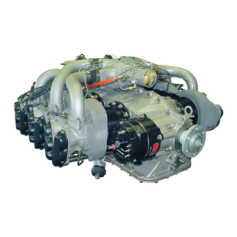
Continental Motors TSI0L-550-C User manual

Operation,
Maintenance,
Installation
Manual
MODEL TSI0L-550-C
FORM NO. OMI-15 FAA APPROVED
© 1998 MARCH 1998

ii
INTENTIONALLY
LEFT
BLANK

About…
iii
CURRENT STATUS OF PAGES AS OF:
MARCH 1998
See “Manual Revisions,” in the introduction section for distribution procedure.
THE ORIGINAL DATE OF THIS PUBLICATION IS MARCH 1998. INSERT LATEST PAGES;
DESTROY SUPERSEDED PAGES.
WARNING
If the user of this manual is uncertain whether all current revisions have been
incorporated into the manual, contact Teledyne Continental Motors. Do not perform
any operation, maintenance, installation or other operation until the manual is
confirmed current.
MODEL: TSI0L-550-C FORM OMI-15
PAGE STATUS PAGE STATUS PAGE STATUS PAGE STATUS
ALL ORIGINAL ALL ORIGINAL ALL ORIGINAL ALL ORIGINAL

Replacement Parts
iv
WARNING
Use only parts meeting the engine type design.
Replacement Parts
Beware of replacement parts, materials and
accessories that may be sold as aircraft quality
but whose origin and quality are not known.
These parts may be deceptively advertised as
"unused," "like new," or "remanufactured," and
purchasers are often unaware that they are not
eligible for use on certificated aircraft. The
hazards involved in installing these types of
parts on your aircraft are obvious.
Know Your Supplier
Many original parts and components are copied
and the copies are sold at discounted prices for
installation on U.S. certified aircraft. An
original manufacturer's part is often used as a
guide to make duplicates that appear to be as
good as the original, but there are many
unknowns about the quality of design, materials,
and workmanship. Other factors that go into
quality parts are the degree of heat treating and
plating, and inspections, tests, and calibrations.
Unfortunately, a cheaply produced part that
looked "as good as the original" is usually found
out too late.
Federal Aviation Regulations FAR 43.13 and
FAR 145.57 specify performance rules for
replacement of parts and materials used in the
maintenance and alteration of United States
certificated aircraft. FAR 91.403, FAR 121.363,
FAR 123.45, and FAR 135.143 (a) holds the
owner/operator responsible for the continued
airworthiness of the aircraft, and that includes
the quality of replacement parts.
Identifying Approved Parts
Approved serviceable replacement parts are
identified by:
1. Federal Aviation Administration (FAA) Form
8130-3 Airworthiness Approval Tag. An
Airworthiness Approval Tag identifies a part or
group of parts that have been approved by an
authorized FAA representative.
2. FAA Technical Standard Order (TSO)
number and identification mark indicating that
the part or appliance was manufactured in
accordance with the requirements of FAR 21
Subpart O.
3. FAA Parts Manufacturer Approval (PMA)
symbol with the manufacturer's name, part
number, make and model of the type certified
product on which the part can legally be
installed stamped on the part. An FAA/PMA is
issued under FAR 21.305. Make and model
information may be on a tag attached to the part.
4. Shipping ticket, invoice, or other document
which verifies that the part was manufactured
by a facility that was holding an FAA Approved
Production Inspection System Certificate issued
under FAR 21 Subpart F, or by a manufacturer
holding an FAA Production Certificate issued
under FAR 21 Subpart G.
5. Certificate of airworthiness for export issued
by governments in countries other than the
United States of America under the provisions
of FAR 21 Subpart N.
It's Your Responsibility
The owner/operator is responsibile for the
continued airworthiness of the aircraft. In
accordance with FAR, certification of materials,
parts and appliances for return to service for use
on aircraft is the responsibility of the
person/agency who signs the approval. To
insure the continued safe operation of your
aircraft, you must exercise great care when
inspecting, testing, and determining the
acceptability of all parts and materials. A very
important part of this is verifying the origin of
all materials, parts, and accessories that are used
on your aircraft.
About…
v
Notice to all users
This manual does not contain operation,
maintenance or installation information for
supplemental type certificated components or
systems. This manual contains information on
engines, components and systems designed, tested
and certified by TCM in accordance with the
pertinent type design data.
The following publication contains operation,
maintenance and installation information only. All
personnel involved with these functions must
thoroughly read and understand the information
provided; these instructions inform of the procedures
necessary to operate, maintain and install an engine
and they must be followed carefully.
This manual contains no warranties, either expressed
or implied.
Publication Format
This publication is formatted for practical use and
ease of reference. Due to the large volume of
information necessary for operation, maintenance
and installation, this manual is divided into three
sections. Each section contains chapters. Chapters
are independently numbered. For example, chapter 1
begins on page 1; chapter 2 begins again with page
1, etc. To locate information easily, use the
Publication Table of Contents and the Chapter
Contents provided at each division.
WARNING
The Operator, Maintenance, Installation,
manual, Overhaul manual, Service
Documents and the Parts Catalog constitute
the instructions for Continued Airworthiness
prepared by TCM as approved by the FAA,
pursuant to FAR Part 33. As required by
FAR § 43.13, each person performing
overhaul, maintenance, alteration or
preventive maintenance on the engine or
accessories must use the methods, techniques
and practices prescribed in the Instructions
for Continued Airworthiness. Failure to
comply with the Instructions for Continued
Airworthiness may result in engine
malfunction, engine failure, injury or death.
The Mechanic
Prior to performing, maintenance, alteration,
overhaul or preventive maintenance the mechanic
must meet requirements of FAR 65 and must follow
FAR Parts 43, 91 and 145 as applicable. Use this
manual in conjunction with Teledyne Continental
Motors (TCM) service documents, related
publications, accessory manufacturer’s instructions,
FAR and FAA Advisory Circulars.
Notes, Cautions and Warnings…
NOTE...
Special interest information which may facilitate
performance of a procedure or operation of
equipment.
CAUTION...
Used to emphasize certain information or
instructions which if disregarded may result in
damage to engine or accessories.
WARNING
Used to provide warning with respect to
information and/or instructions which if
disregarded will endanger personnel and/or
severely damage the engine resulting in
subsequent engine malfunction or failure.
Notes, cautions and warnings do not impose undue
restrictions. They are inserted to obtain maximum
safety, efficiency and performance. Abuse, misuse
or neglect of equipment can cause eventual engine
malfunction or failure.

Replacement Parts
vi
INTENTIONALLY
LEFT
BLANK

vii
Table of Contents
FRONT SECTION
COVER PAGES PAGE
Status Page ....................................................................................... iii
Replacement Parts Warning............................................................. iv
Notice To All Users .......................................................................... v
Notes, Cautions and Warnings ......................................................... v
Introduction .................................................................................... 1-1
AIRWORTHINESS LIMITATIONS
Airworthiness Limitations..............................................................AWL
SECTION 1 ENGINE OPERATION
CHAPTER PAGE
1 Normal Engine Operation....................................................... 1-1
2 Emergency Procedures............................................................ 2-1
3 Operation Under Abnormal
Environmental Conditions....................................................... 3-1
4 Engine Operating Specifications............................................. 4-1
SECTION 2 ENGINE MAINTENANCE
CHAPTER PAGE
1 Scheduled Maintenance and Servicing Fluids ........................ 1-1
2 Engine Preservation and Storage............................................ 2-1
3 Tools, Equipment, Sealants and Lubricants............................ 3-1
4 Troubleshooting ...................................................................... 4-1
5 Standard Practices .................................................................. 5-1
6 Engine Maintenance................................................................ 6-1
7 Exhaust and Turbocharger System.......................................... 7-1
8 Ignition System ........................................................................ 8-1
9 Fuel Injection System .............................................................. 9-1
10 Induction System ..................................................................... 10-1
11 Liquid Cooling System............................................................. 11-1
12 Air Conditioning...................................................................... 12-1
13 Electrical Charging System..................................................... 13-1
14 Starter and Starter Adapter..................................................... 14-1
15 Lubrication System.................................................................. 15-1
16 Cylinders ................................................................................. 16-1
17 Crankcase................................................................................ 17-1
18 Crankshaft and Camshaft........................................................ 18-1
19 Post Maintenance Adjustment and Test .................................. 19-1
SECTION 3 ENGINE INSTALLATION
CHAPTER PAGE
1 Engine Installation .................................................................. 1-1

Replacement Parts
viii
INTENTIONALLY
LEFT
BLANK

1-1
INTRODUCTION
Chapter Contents Page
Introduction............................................................................................1-2
Scope ......................................................................................................1-2
Definition of Terms ................................................................................ 1-2
Manual Revisions...................................................................................1-3
Related Publications .............................................................................. 1-3
Service Documents ................................................................................. 1-4
Service Reports and Inquiries ................................................................1-4
Engine Model Code Description............................................................1-4
Engine Design Features......................................................................... 1-4
Glossary .................................................................................................1-6

1-2
INTENTIONALLY
LEFT
BLANK
Introduction

1-3
INTRODUCTION
This operation, maintenance and installation
manual and publications listed in Section 1-5,
"Related Publications," contain the
information necessary to operate, maintain
and install an aircraft engine.
For a list of chapters contained in this manual
refer to the Chapter Index on page vii.
For a list of subject matter, figures and tables
contained in each chapter, see the first page
of each chapter. The pages, figures and
tables contained in this publication are
numbered consecutively.
This manual covers the TSI0L-550-C engine.
SCOPE
This publication contains the information
necessary to operate, perform scheduled
maintenance, adjust and test and install the
above model engine.
DEFINITION OF TERMS
In this manual, front, rear, left and right refer
to the engine as viewed from the accessory
end. The accessory end is the rear and the
propeller flange is the front of the engine.
Cylinders are numbered starting from the
rear, with odd numbers on the right and even
numbers on the left.
MANUAL REVISIONS
Teledyne Continental Motors manuals are
revised as necessary. Revisions to this
manual will be furnished to purchasers who
fill out and return the registration post card
located in the front of this manual.
Page iii, "Current Status Of Pages," is
updated at each revision. Remove and discard
the old page iii. Insert the new page iii as a
record of which revisions have been
incorporated into the manual.
WARNING
If for any reason the user of this manual
is uncertain whether all current revisions
have been incorporated into the manual,
contact Teledyne Continental Motors or
a TCM Distributor to confirm the
manual is the most current revision. Do
not use the manual and do not perform
any operation, maintenance or
installation procedures or other
operations upon the engine or
accessories until the manual has been
confirmed to be current.
This manual is current and correct to the
best of Teledyne Continental Motors
knowledge at the time of publication.
Teledyne Continental Motors solicits and
encourages users comments regarding
suggested changes to this manual (a post
card is provided at the front of the
manual for this purpose.) Routine
recommended changes or questions
should be sent to:
Teledyne Continental Motors
P.O. Box 90
Mobile, Alabama 36601
ATTN:Technical Publications
Department
If the user observes incorrect
information or mistakes in this
publication that may affect safety in any
manner, immediately call the Technical
Publications Department of Teledyne
Continental Motors at (334) 438-3411, or
contact a Teledyne Continental Motors
Distributor or the Federal Aviation
Administration.
Introduction

1-4
RELATED PUBLICATIONS
The following is a listing of related manuals:
1. Overhaul Manual for TSI0L-550-C, Form OH-15.
2. Illustrated Parts Catalog for TSI0L-550-C Aircraft Engine, Form IPC-15.
3. Teledyne Continental Motors Aircraft Engine Service Documents (including service
bulletins).
4. Fuel Injection Manual, Form X30593A.
5. Starter Service Instructions, Form X30592.
6. Alternator Maintenance and Parts Catalog, Form No. X30631 A.
The above publications can be ordered through your Teledyne Continental Motors Distributor
or ordered directly, if prepaid, from:
Teledyne Continental Motors
P. 0. Box 90
Mobile, Alabama 36601
ATTN: Publication Sales Department
Telephone: (334) 438-3411
For price information on the above publications request TCM Publications Pricing Index of
Current Publications and Optional Publications.
7. Slick Ignition Systems Master Service Manual Index and Order Form No. F-1 1 00.
Order through:
Slick Aircraft Products, Unison Industries
530 Blackhawk Park Avenue
Rockford, Illinois 61104
ATTN: Subscription Department
Telephone: (815) 965-4700
8. American Society for Testing and Materials (ASTM). Order through:
ASTM 1916 Race Street, Philadelphia, PA.
19103-1187 USA
Ph: (215) 299-5400
9. Overhaul Manual for Aircraft System Turbochargers and Overhaul Manual for
Aircraft System Valves and Controllers. Order Through:
Airesearch 232 W. 190 Street
Torrence, California
90504-6094, (213) 323-9500.
Introduction

1-5
SERVICE DOCUMENTS.
Teledyne Continental Motors service
documents are divided into six categories: (1)
Mandatory Service Bulletin, (2) Critical
Service Bulletin, (3) Service Bulletin, (4)
Service Information Directive (5) Service
Information Letter and (6) Special Service
Notice (SSN). See Section 1-5, "Related
Publications," for service document ordering
information.
SERVICE DOCUMENT CATEGORY
DEFINITIONS
CATEGORY 1: "MANDATORY SERVICE
BULLETIN" (MSB)- Service documents
relating to known or suspected hazards to
safety that have been incorporated in whole or
in part in an Airworthiness Directive (AD)
issued by the FAA or have been issued, at the
direction of FAA, by the manufacturer in order
to require compliance with an already issued
AD (or an equivalent issued by another
country's airworthiness authority).
CATEGORY 2: "CRITICAL SERVICE
BULLETIN" (CSB)- Service documents (not
included in Category 1) that have been
determined by the product manufacturer to
constitute a threat to continued safe operation
of an aircraft or to persons or property on the
ground unless some specific action (inspection,
repair, replacement, etc..) is taken by the
product owner or operator. Documents in this
category may be incorporated in an
Airworthiness Directive issued by the FAA.
CATEGORY 3: "SERVICE BULLETIN"
(SB)- Service documents (not included in
Categories 1 and 2) considered by the product
manufacturer to constitute a substantial
improvement to the inherent safety of an
aircraft or component of an aircraft. This
"Service Bulletin" category also includes
updates of instructions for continued
airworthiness.
CATEGORY 4: "SERVICE
INFORMATION DIRECTIVE" (SID)-
Service documents (not included in Categories
1, 2 or 3) that have been determined by the
manufacturer to be of value to an
owner/operator in the use of a product by
enhancing safety, maintenance or economy.
CATEGORY 5: "SERVICE
INFORMATION LETTER" (SIL)- This
category includes all information (not included
in Categories 1 through 4) that may be of use to
the owner/operator or maintainer of the aircraft.
CATEGORY 6 “SPECIAL SERVICE
NOTICE” (SSN)-TCM may issue a Special
Service Notice when a product condition can be
rectified by direct contact with each customer
to whom the product was delivered. Special
service notices will be upgraded to Service
Bulletins if confirmation of compliance with
the Special Service Notice cannot be verified
by TCM.
SERVICE REPORTS AND
INQUIRIES.
If for any reason you have an inquiry or require
technical assistance, contact your local TCM
distributor or TCM field representative.
Requests for copies of Teledyne Continental
Aircraft Engine service publications should be
made through your distributor or Teledyne
Continental Motors, P. 0. Box 90, Mobile, AL
36601, ATTN: Publications Sales Department.
ENGINE MODEL CODE
DESCRIPTION
TSIOL-550-C (x)
TS Turbosupercharged
I Fuel injected
O Horizontally opposed
L Liquid cooled
550 Displacement in cubic inches
C Model designation
(x) Specification number
ENGINE DESIGN FEATURES
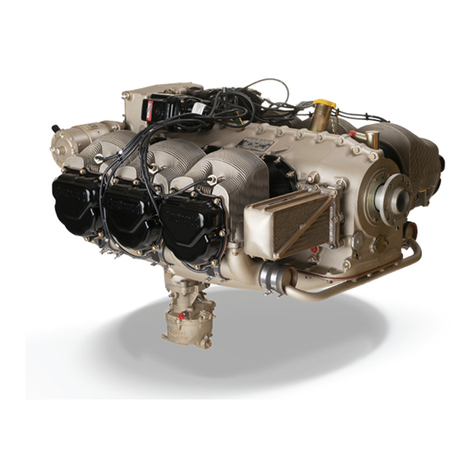
The TSIOL-550-C engine is a direct drive,
turbocharged, fuel injected, liquid cooled, six
cylinder horizontally opposed engine
incorporating a wet sump and a runner type
induction system with an engine mounted
throttle body.
Introduction

1-6
The induction system also includes an airframe
mounted aftercooler with a manifold pressure
relief valve (overboost valve) and a sonic
venturi nozzle to provide air for cabin
pressurization.
The engine has a 550 cubic inch displacement,
5.25 inch bore, 4.25 inch stroke, and a 7.5:1
compression ratio.
The firing order is 1-6-3-2-5-4.
Exhaust system runners mounted below the
cylinder heads direct the exhaust to the engine-
mounted turbocharger and wastegate which is
regulated by a controller. The exhaust gas driven
turbocharger system is comprised of a sloped
controller, overboost valve, wastegate assembly,
turbine and compressor assembly, and
associated hoses, linkage, and ducting. The
turbocharger assembly is lubricated by engine
oil.
The crankshaft flange has six bolt holes, two
dowel holes and a center pilot extension to
accommodate a variable pitch propeller.
The engine crankshaft is balanced with
pendulum-type torsional damper weights.
Removable hydraulic tappets, push rods, rocker
arm bushings, valves, etc., are lubricated by
engine oil pressure. Roto coils are used for
exhaust valve rotation.
A wet oil sump is located at the bottom of the
crankcase and positive displacement oil pump is
located at the lower rear of the crankcase. Oil
pressure is maintained by a pressure relief valve
in the oil pump housing.
A geared, right-angle drive starter adapter with a
DC current starter motor is used for cranking.
Two gear-driven magnetos are attached to the
upper rear, front portion of the crankcase. A
direct drive alternator is located on the right-
front of the crankcase.
The coolant system includes a gear driven
centrifugal flow pump, externally mounted on
the starter adapter which supplies coolant flow
to and from the cylinders by means of a dual
type runner manifold on top of the cylinders.
Coolant flow from the cylinders is directed to an
engine mounted customer supplied reservoir.
Coolant is then directed through the remote
customer supplied radiator before returning to
the coolant pump.
A pneumatic pump, and propeller governor are
furnished by the airframe manufacturer.
Introduction

1-7
GLOSSARY
BURNING: As applied to valve heads this term
indicates roughening or erosion due to high
temperature gases escaping past valve faces. In
other instances, it indicates drawing of the temper
of steel parts to a soft (blue) condition, as a result
of overheating, during an absence of lubrication
on moving surfaces, such as, gear teeth subject to
high loading.
BURR: A sharp or rough projection of metal.
CHAFING: Rubbing action between adjacent or
contacting parts under light pressure which results
in wear.
COLD FLOW: Term used to describe deep and
permanent impressions or cracks caused by hose
clamp pressure.
CRACK: A partial separation of material usually
caused by vibration, overloading, internal
stresses, improper assembly or fatigue.
DENT: A rounded hollow in the surface.
ELONGATE: To stretch out or lengthen.
EROSION: Carrying away of material by the
flow of hot gases, grit or chemicals.
FRETTING: A condition of surface erosion
caused by a slight movement between two parts
that are fastened together.
GALLING: A severe condition of chafing or
fretting in which a transfer of metal from one part
to another occurs. It is usually caused by a slight
movement of mated parts having limited relative
motion and under high loads.
GROOVED SURFACE: Shallow channels, wider
than scratches and usually smooth resulting from
wear effected by concentrated contact stress.
NICK: A sharp sided gouge or depression with a
"V" shaped bottom which is generally the result
of careless handling of tools and parts.
PEENING: A series of blunt depressions in a
surface
PITTING: The formation of pockets of corrosion
on the surface of a metal.
RUNOUT: Eccentricity or wobble of a rotating
part. Eccentricity of two bored holes or two shaft
diameters. A hole or bushing out of square with a
flat surface. Usually measured with a dial
indicator, and limits stated indicate full deflection
of indicator needle in one revolution of part or
indicator support.
SCORING: Deep grooves in a surface caused by
abrasion. Scoring is caused by fine hard particles
that are forced between moving surfaces, as in a
bearing and journal, or by galling when a moving
part is not supplied with lubricant.
SPALLING: Distress to a loaded surface in which
chips of the hardened surface are broken out.
Introduction

1-8
INTENTIONALLY
LEFT
BLANK
Introduction

Section 1
Engine Operation
Section Contents Chapter
Normal Engine Operation ..........................................................1
Emergency Procedures ...............................................................2
Operations Under Abnormal
Environmental Conditions ..........................................................3
Engine Operating Specifications .................................................4

INTENTIONALLY
LEFT
BLANK

1-1
Chapter 1
Engine Operation
Chapter Contents Page
Normal Operating Procedures ......................................... 1-3
Preflight............................................................................ 1-3
Starting ............................................................................. 1-4
Flooded Engine................................................................. 1-4
Hot Starts ......................................................................... 1-5
Before Takeoff Check ....................................................... 1-5
Power Control .................................................................. 1-5
Takeoff .............................................................................. 1-6
Climb ................................................................................ 1-6
Cruise................................................................................ 1-6
Descent ............................................................................. 1-6
Landing............................................................................. 1-6
Engine Shutdown .............................................................. 1-6

1-2
INTENTIONALLY
LEFT
BLANK
Engine Operation
Table of contents
Other Continental Motors Engine manuals

Continental Motors
Continental Motors GTSIO-520 SERIES User manual

Continental Motors
Continental Motors N56 Troubleshooting guide

Continental Motors
Continental Motors C75 Troubleshooting guide

Continental Motors
Continental Motors O-470-B User manual

Continental Motors
Continental Motors TSIO-520-BE User manual

Continental Motors
Continental Motors C-125 User manual

Continental Motors
Continental Motors TSIOL-550-C User manual

Continental Motors
Continental Motors GO-300-A User manual

Continental Motors
Continental Motors O-200-D User manual

Continental Motors
Continental Motors R688-46 User manual