Beninca DU.350N User manual

DU.350N
DU.350NV
DU.350NVE
DU.350NGE
L8543133
05/2015 R1
UNIONE NAZIONALE COSTRUTTORI
AUTOMATISMI PER CANCELLI, PORTE
SERRANDE ED AFFINI


3
400
267
400
400
362
300
149
64
70
DU.110 DU.350
DU.90
32,5
Dimensioni d’ingombro / Overall dimensions / Abmessungen
Dimensions d’encombrement / Dimensiones exteriores / Wymiary gabarytowe

4
1
Arresto in chiusura.
Stop when closing.
Endanschlag zur Schließung.
Arrêt en fermeture.
Tope de cierre.
Chwytak blokujący podczas zamykania.
Arresto in apertura.
Stop when opening.
Endanschlag zur Öffnung.
Arrêt en ouverture.
Tope en apertura.
Chwytak blokujący podczas otwierania.
2
Standard.
Standard.
Standard.
Standard.
Standard.
Standard.
Interno.
Inside.
Innenraum.
Intérieur.
Interior.
Wnętrze obudowy
Apre.
Open.
Öffnen.
Ouvre.
Abre.
Otwarcie
Apre.
Open.
Öffnen.
Ouvre.
Abre.
Otwarcie
Posizione motoriduttore.
Reduction gear position.
Stellung Getriebemotor.
Position motoréducteur.
Posición del motorreductor.
Pozycja siłownika
Posizione motoriduttore.
Reduction gear position.
Stellung Getriebemotor.
Position motoréducteur.
Posición del motorreductor.
Pozycja siłownika
Anta.
Gate wing.
Torflügel.
Porte.
Hoja.
Skrzydło bramy.
Anta.
Gate wing.
Torflügel.
Porte.
Hoja.
Skrzydło bramy.
Anta.
Gate wing.
Torflügel.
Porte.
Hoja.
Skrzydło bramy.
Anta.
Gate wing.
Torflügel.
Porte.
Hoja.
Skrzydło bramy.
110° 110°
90° 90°
Muro.
Wall.
Wand.
Mur.
Muro.
Mur
Muro.
Wall.
Wand.
Mur.
Muro.
Mur
Muro.
Wall.
Wand.
Mur.
Muro.
Mur
Muro.
Wall.
Wand.
Mur.
Muro.
Mur
Apre.
Open.
Öffnen.
Ouvre.
Abre.
Otwarcie
Apre.
Open.
Öffnen.
Ouvre.
Abre.
Otwarcie

5
Leva di collegamento.
Connection lever.
Anschlußhebel.
Levier de liaison.
Leva de conexión.
Dźwignia połączenia.
Staffa del motore.
Motor flask.
Motorbügel.
Etrier du moteur.
Acoplamiento al motor.
Strzemiączko silnika.
Staffa del gruppo di traino.
Drive unit flask.
Bügel der Zuggruppe.
Etrier du groupe de traction.
Acoplamiento del grupo de tracción.
Strzemiączko zespołu pociągnika.
Fermo meccanico per apertura regolabile DU.350ST.
Mechanical stopper for DU.350ST adjustable opening.
Einstellbarer mechanischer Anschlag für DU.350ST-Öffnung.
Butée mécanique pour ouverture réglable DU.350ST.
Tope mecánico para apertura regulable DU.350ST.
Mechaniczny ogranicznik służący do regulacji stopnia otwierania DU.350ST.
V
110°
70
200
200
X
Y
Esterno - Outside - Außen - Extérieur - Exterior - Zewnątrz.
Interno - Inside - Innen - Intérieur - Interior - Wewnątrz
Cancello con apertura ante a 110°.
Gate with 110° opening.
Tor mit Flügelöffnung bis 110°.
Portail avec ouverture des vantaux à 110°.
Cancela con apertura de hojas hasta 110°.
Brama z otwarciem skrzydeł na 110°.
In tabella si riportano alcune quote minime X in base
ad alcuni spessori di portone Y.
This table shows some min. X dimensions based
on gate thickness Y.
Die Tabelle enthält einige Mindestwerte X aufgrund
einiger Tordicken Y.
Dans le tableau sont indiqués quelques cotes mini-
males et quelques épaisseurs de porte Y.
En la tabla se exponen algunas cotas mínimas X en
base a algunos espesores del portón Y.
W tabeli podane są niektóre minimalne odległości
X w zależności od grubości bramy Y.
3
4
X Y
130 30
115 40
100 50
85 60
70 70
55 80

6
DU.350NVE/NGE
Segnale ENCODER
Filo Verde
Positivo ENCODER
Filo Marrone
Negativo ENCODER
Filo Bianco
ENCODER signal
Green wire
ENCODER positive
Brown wire
ENCODER negative
White wire
ENCODER-Signal
Grün Leiter
ENCODER Pluspol
Braun Leiter
ENCODER Minuspol
Weiß Leiter
Signal ENCODEUR
Fil vert
Positif ENCODEUR
Fil brun
Négatif ENCODEUR
Fil blanc
Señal ENCODER
Hilo verde
Positivo ENCODER
Hilo marróne
Negativo ENCODER
Hilo blanco
Sygnał ENKODERA
Zielony przewód
Dodatni ENKODERA
Brązowy
przewód
Ujemny ENKODERA
Biały przewód
Collegamenti elettrici / Wire diagram / Elektrische Anschlüsse
Branchements électriques / Conexiones eléctricas / Połączenia elektryczne
Legenda:
1 Motoriduttore DU.350N
2 Fotocellule
3 Selettore a chiave (da esterno) o tastiera digitale
4 Lampeggiante
5 Antenna
6 Centrale elettronica.
Legenda:
1 Motoreducer DU.350N
2 Photo-electric cells
3 Key selector (external) or digital keyboard
4 Flash-light
5 Antenna
6 Electronic board.
Zeichenerklärung:
1 Getriebemotor DU.350N
2 Fotozelle
3
Schlüssel-Selektor (außenliegend) oder Digital-Tastatur
4 Blinker
5 Antenne
6 Elektroschrank.
Légende:
1 Moteur-réducteur DU.350N
2 Photocellule
3 Selecteur à clé (d’extérieur) ou clavier digital
4 Clignotant
5 Antenne
6 Centrale électronique.
Leyenda:
1 Motorreductor DU.350N
2 Fotocélulas
3 Selectores a llave (de superficie).
4 Relampagueador.
5 Antena.
6 Central electrónica.
Objaśnienia:
1 Siłownik DU.350N
2 Fotokomórki
3 Przełącznik kluczowy (zewnętrzny) lub panel z przyciskami
4 Światło migające
5 Antena
6 Centralka elektroniczna
4
12
RG 58
6
3x1,5 min
230 V
5
2
1
2x1,5
2x1
2x1
4x1
4x1,5
4x1,5
N.B.: Tenere separati i cavi di potenza da quelli ausiliari.
N.B.: The power cables must be kept separated from the auxiliary cables.
Wichtig: Leistungskabel von Hilfskabeln getrennt halten.
N.B.: Séparer les câbles de puissance des câbles auxiliaires.
N.B.: Tener separados los cables de potencia de los auxiliares.
Uwaga: należy trzymać w oddali przewody zasilania od przewodów pomocniczych.

7
AVVERTENZE
E' vietato l'utilizzo del prodotto per scopi o con modalità non
previste nel presente manuale. Usi non corretti possono essere
causa di danni al prodotto e mettere in pericolo persone e cose.
Si declina ogni responsabilità dall'inosservanza della buona
tecnica nella costruzione dei cancelli, nonché dalle deformazioni
che potrebbero verificarsi durante l'uso.
Conservare questo manuale per futuri utilizzi.
L'installazione deve essere effettuata da personale qualificato
nel pieno rispetto delle normative vigenti.
I materiali dell'imballaggio non devono essere lasciati alla
portata dei bambini in quanto fonte di potenziale pericolo. Non
disperdere nell'ambiente i materiali di imballo, ma separare le
varie tipologie (es. cartone, polistirolo) e smaltirle secondo le
normative locali.
L’installatore deve fornire tutte le informazioni relative al funzion-
amento automatico, manuale e di emergenza dell'automazione,
e consegnare all’utilizzatore dell’impianto le istruzioni d’uso.
•Prevedere sulla rete di alimentazione un interruttore/
sezionatore onnipolare con distanza d’apertura dei
contatti uguale o superiore a 3 mm.
Verificare che a monte dell’impianto elettrico vi sia un interrut-
tore differenziale e una protezione di sovracorrente adeguati.
Alcune tipologie di installazione richiedono il collegamento
dell'anta ad un impianto di messa a terra rispondente alle vigenti
norme di sicurezza.
Durante gli interventi di installazione, manutenzione e ripa-
razione, togliere l’alimentazione prima di accedere alle parti
elettriche.
Questo prodotto non è destinato a essere utilizzato da persone
(bambini inclusi) con capacità fisiche, sensoriali o mentali
ridotte, o con mancanza di conoscenze adguate, a meno che
non siano sotto supervisione o abbiano ricevuto istruzioni d'uso
da persone responsabili della loro sicurezza.
Le descrizioni e le illustrazioni presenti in questo manuale non
sono impegnative. Lasciando inalterate le caratteristiche es-
senziali del prodotto il fabbricante si riserva il diritto di apportare
qualsiasi modifica di carattere tecnico, costruttivo o commer-
ciale senza impegnarsi ad aggiornare la presente pubblicazione.
Dichiarazione CE di Conformità
Dichiarazione in accordo alle Direttive 2004/108/CE(EMC); 2006/95/CE(LVD)
Fabbricante:
Automatismi Benincà SpA
Indirizzo:
Via Capitello, 45 - 36066 Sandrigo (VI) - Italia
Dichiara che il prodotto:
Attuatore elettromeccanico 230Vac per cancelli a battente modello:
DU.350N - DU.350NV - DU.350NVE- DU.350NGE
è conforme alle condizioni delle seguenti Direttive CE:
• DIRETTIVA 2004/108/CE DEL PARLAMENTO EUROPEO E DEL CONSIGLIO del 15 dicembre 2004 concernente il
ravvicinamento delle legislazioni degli Stati membri relative alla compatibilità elettromagnetica e che abroga la direttiva 89/336/
CEE, secondo le seguenti norme armonizzate:
EN 61000-6-2:2005, EN 61000-6-3:2007.
• DIRETTIVA 2006/95/CE DEL PARLAMENTO EUROPEO E DEL CONSIGLIO del 12 dicembre 2006 concernente il
ravvicinamento delle legislazioni degli Stati membri relative al materiale elettrico destinato ad essere adoperato entro taluni limiti
di tensione, secondo le seguenti norme armonizzate:
EN 60335-1:2002 + A1:2004 + A11:2004 + A12:2006 + A2:2006 + A13:2008; EN 60335-1-103:2003.
se applicabile:
• DIRETTIVA 1999/5/CE DEL PARLAMENTO EUROPEO E DEL CONSIGLIO del 9 marzo 1999 riguardante le apparecchiature
radio e le apparecchiature terminali di telecomunicazione e il reciproco riconoscimento della loro conformità, secondo le seguenti
norme armonizzate:
ETSI EN 301 489-3 V1.4.1 (2002) + ETSI EN 301 489-1 V1.4.1 (2002) + ETSI EN 300 220-3 V1.1.1 (2000) + EN 60950-1 (2001)
Benincà Luigi, Responsabile legale.
Sandrigo, 02/02/2015.

8
Introduzione
Ci congratuliamo con voi per aver scelto il motoriduttore
DU.350.
Tutti gli articoli della vasta gamma Benincà sono il frutto di
una ventennale esperienza nel settore degli automatismi
e di una continua ricerca di nuovi materiali e di tecnologie
all’avanguardia.
Proprio per questo, oggi siamo in grado di offrire dei prodotti
estremamente affidabili che, grazie alla loro potenza,
efficacia e durata, soddisfano pienamente le esigenze
dell’utente finale.
Notizie generali
Per un buon funzionamento delle automazioni in oggetto,
il cancello da automatizzare dovrà rispondere alle seguenti
caratteristiche:
- buona robustezza e rigidità
- ogni anta deve avere una sola cerniera (eventualmente
eliminare le superflue all’atto dell’automazione)
- le cerniere devono presentare giochi minimi e permettere
che le manovre manuali siano dolci e regolari
- in posizione di chiusura le ante devono combaciare fra
loro per tutta l’altezza.
1. Caratteristiche generali
Sistema a scomparsa totale che non altera l’estetica del
cancello.
Semplice ed affidabile può essere installato su qualsiasi
cancello a battente fino a max. 4 m per anta (max 3m per
versione DU350NV).
Il movimento è silenzioso e regolare grazie ad un sistema
di leve che adegua la velocità alle varie fasi della manovra.
Il motoriduttore, interamente a bagno d’olio, non permette
l’infiltrazione d’acqua o la formazione di condensa che
potrebbero compromettere irrimediabilmente la funzionalità
del motore.
Non necessita di elettroserrature in quanto il sistema
irreversibile assicura il blocco delle ante.
L’installazione è di facile esecuzione; infatti, una volta
interrata la cassa, il motoriduttore viene fissato con viti e
dadi in acciaio inox.
Lo sblocco per la manovra manuale avviene mediante
leva speciale fornita in dotazione (art. SB.DU350L), oppure
tramite chiave personalizzata (art. SB.DU350K).
Le casse di fondazione sono sottoposte al trattamento di
cataforesi e il coperchio è inoltre verniciato, per coadiuvare la
massima durata nel tempo ad un ottimale risultato estetico.
Con l’applicazione del dispositivo DU.180N si ottiene
un’apertura a 180° (per ante con lunghezza non superiore a 2
m). Lo stesso DU.180N può essere adottato come soluzione
per l’automazione di passaggi speciali.
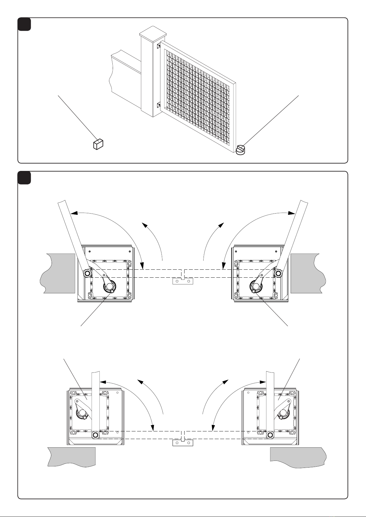
2. Arresti meccanici (fig. 1)
Il cancello da automatizzare deve disporre di arresto
meccanico sia in apertura che in chiusura, in quanto il
DU.350V/DU350NV non dispone di finecorsa elettromagnetici.
E' comunque disponibile come accessorio opzionale il kit
finecorsa DU.350FC di rapida installazione e regolazione.
3. Posa della cassa di fondazione
Fare riferimento alle istruzioni fornite in dotazione con la
cassa di fondazione DU.350CF.
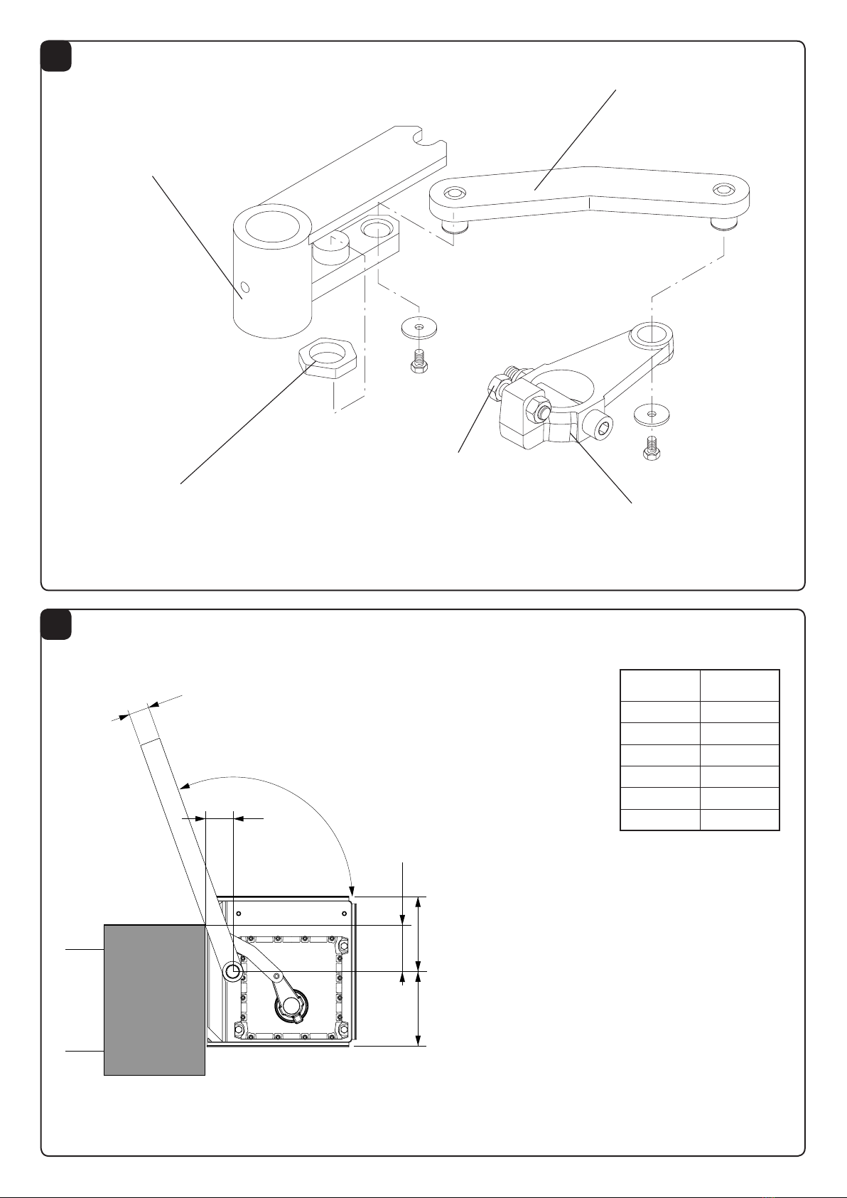
4. Fissaggio del motoriduttore
4.1
Fissare il motoriduttore con n° 4 dadi esagonali M10 inox
(in dotazione) sulle viti sporgenti dalla cassa interrata.
N.B.: Nella cassa sono presenti 8 viti; utilizzare quelle
rispondenti alle esigenze seguendo le istruzioni di fig. 4.
4.2 Collegare il gruppo di traino con la staffa del motore
tramite la leva di collegamento (Fig.7).
4.3 Con l'anta in appoggio sul fermo di arresto di chiusura,
regolare la vite V di Fig.7 ad una distanza di 1/2mm
dalla leva di collegamento (solo nel caso di montaggio
standard).
4.4 È disponibile come accessorio il fermo meccanico
per apertura regolabile(DU.350ST) da posizionare
nell'apposita sede sulla staffa di traino, come indicato
in Fig.7
4.5 Prima di serrare i dadi M10, controllare che il motoriduttore
sia ben appoggiato al fondo della cassa, altrimenti
spessorare dove richiesto, tenendo presente che il
motoriduttore deve essere in piano (verificare ciò tramite
livella).
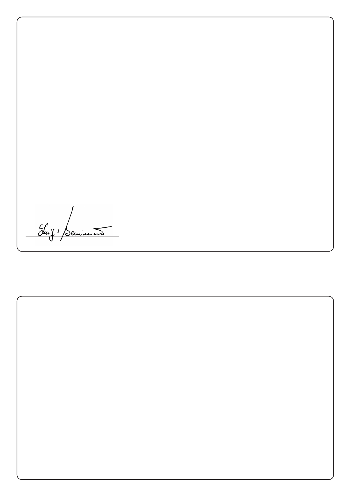
5. Apertura a 110° (fig. 8)
Per un'apertura a 110°, calcolare che la quota X tra perno
e spigolo del portante sia tale da permettere la rotazione
tenendo conto dello spessore del portone Y.
6. Apertura a 180°
Si può realizzare anche l’apertura a 180° tramite l’apposito
dispositivo art. DU.180N. Tale soluzione è consigliata
per lunghezze anta fino a 2 m; si può utilizzare anche per
lunghezze maggiori, ma il funzionamento diventa meno
dolce e regolare.
ATTENZIONE
Tutti i prodotti Benincà sono coperti da polizza assicurativa
che risponde di eventuali danni a cose o persone causati
da difetti di fabbricazione, richiede però la marcatura CE
della ”macchina” e l’utilizzo di componenti originali Benincà.
DATI TECNICI DU.350N
DU.NGE
DU.350NV
DU.350 NVE
Alimentazione 230 Vac 230 Vac
Potenza assorbita 310 W 310 W
Corrente assorbita 1,4 A 1,4 A
Coppia 450 Nm 270 Nm
Classe isolamento mot. F F
Rumorosità < 70 dB < 70 dB
Tempo man. anta (90°) 18 s (1). 11 s (1).
Peso max. anta 500 kg 500 kg
Lunghezza max. anta 3,5 m (2) 3 m (2)
Intermittenza lavoro Uso intensivo Uso intensivo
Lubrificazione AGIP Blasia 32 AGIP Blasia 32
Condensatore 12,5 µF 12,5 µF
Grado IP IP67 IP67
Peso DU.350N/350NV 18,5 kg 20,3 kg
(1) Con rallentamento disabilitato.
(2) È possibile automatizzare anche ante di lunghezza maggiore ma il
funzionamento diventa meno dolce e regolare.

9
WARNING
The product shall not be used for purposes or in ways other than
those for which the product is intended for and as described in
this manual. Incorrect uses can damage the product and cause
injuries and damages.
The company shall not be deemed responsible for the non-
compliance with a good manufacture technique of gates as
well as for any deformation, which might occur during use.
Keep this manual for further use.
Qualified personnel, in compliance with regulations in force,
shall install the system.
Packaging must be kept out of reach of children, as it can be
hazardous. For disposal, packaging must be divided the various
types of waste (e.g. carton board, polystyrene) in compliance
with regulations in force.
The installer must supply all information on the automatic,
manual and emergency operation of the automatic system and
supply the end user with instructions for use.
•An omnipolar switch/section switch with remote
contact opening equal to, or higher than 3mm
must be provided on the power supply mains..
Make sure that before wiring an adequate differential switch
and an overcurrent protection is provided.
Pursuant to safety regulations in force, some types of installa-
tion require that the gate connection be earthed.
During installation, maintenance and repair, cut off power sup-
ply before accessing to live parts.
This product is not to be used by persons (including children)
with reduced physical, sensory or mental capacity, or who are
unfamiliar with such equipment, unless under the supervision
of or following training by persons responsible for their safety.
Descriptions and figures in this manual are not binding. While
leaving the essential characteristics of the product unchanged,
the manufacturer reserves the right to modify the same under
the technical, design or commercial point of view without nec-
essarily update this manual.
CE Declaration of Conformity
Declaration in accordance with Directives 2004/108/CE(EMC); 2006/95/CE(LVD)
The Manufacturer:
AUTOMATISMI BENINCÀ SPA
Address:
Via Capitello, 45 - 36066 Sandrigo (VI) - Italy
Declares that the product:
Electromechanical actuator 230V AC for swing gates, model:
DU.350N - DU.350NV - DU.350NVE- DU.350NGE
conforms with the requirements of the following EU Directives:
•DIRECTIVE 2004/108/CE OF THE EUROPEAN PARLIAMENT AND COUNCIL, 15 December 2004, in relation to the
harmonisation of the legislation of member states regarding electromagnetic compatibility , in abrogation of Directive 89/336/
CEE, per the following harmonised standards:
EN 61000-6-2:2005, EN 61000-6-3:2007.
• DIRECTIVE 2006/95/CE OF THE EUROPEAN PARLIAMENT AND COUNCIL, 12 December 2006, in relation to the
harmonisation of the legislation of member states regarding electrical material intended to be used within certain voltage ranges,
per the following harmonised standards:
EN 60335-1:2002 + A1:2004 + A11:2004 + A12:2006 + A2:2006 + A13:2008; EN 60335-1-103:2003.
as applicable:
• DIRECTIVE 1999/5/CE OF THE EUROPEAN PARLIAMENT AND COUNCIL, 9 March 1999 in relation to radio equipment and
telecommunications terminals and the mutual recognition of their conformity, per the following harmonised standards:
ETSI EN 301 489-3 V1.4.1 (2002) + ETSI EN 301 489-1 V1.4.1 (2002) + ETSI EN 300 220-3 V1.1.1
(2000) + EN 60950-1 (2001)
Benincà Luigi, Legal representative.
Sandrigo, 02/02/2015.

10
Introduction
Thank you for choosing our DU.350 ratiomotor. All items
in the wide Benincà production range are the result of
twenty-years’ experience in the automatism sector and
of continuous research for new materials and advanced
technologies.
We are, therefore, in the position to offer higly reliable
products that due to their power, effectiveness and useful
life, fully satisfy the final user’s requirements.
General information
For an efficient operation of these automatisms, the gate
must have the following features:
- good stoutness and stiffness
- every wing must have one only hinge (if necessary,
eliminate the others).
- all hinges must have positive clearances and permit
smooth and regular manual operations.
- when wings are closed their height have to fit together.
1. General features
This entirely concealing system does not alter the external
aspect of the gate.
Easy to use and reliable, this system can be installed on
any swing gate, up to 4m width per gate leaf (3 m max for
DU350NV model).
The movement is smooth and noiseless thanks to a lever
system that adjusts speed to the various operating phases.
The oil submersed geared motor prevents any water leakage
or condensate which might irremediably compromise the
motor operation.
No electric locks are required as the irreversible system
ensures the locking of the gate leaves.
The system is easy to install. Once the casing is underground,
in fact, the geared motor is fixed with stainless steel nuts
and screws.
The system is released by hand through the special lever
supplied (item SB.DU350L), or through customized key (item
SB.DU350K).
The foundation casings are treated by cataphoresis and
the cover is varnished for a longer duration and excellent
aesthetic result.
With the application of the DU.180N device, a 180° opening
is obtained (with gate leaves not wider than 2 m). The
DU.180N can be adopted for the automation of special
passages.
2. Mechanical stops (fig. 1)
The gate to automate must have an opening and closing
mechanical stop as the DU.350N/DU.350NV is not equipped
with electro-magnetic limit stops. The DU.350FC limit switch
kit, easy to install and adjust, is in any case available.
3. Laying of the foundation casing
Refer to instructions supplied with the DU.350CF foundation
casing.
4. Motoreducer fixing
4.1
Fix the motoreducer with the 4 stainless steel M10
hexagon nut (part of the supply) that are fitted onto the
screws projecting from the embedded box.
P.N. In the box there are 8 screws; use the ones that are suitable
to the requirements as per instructions given in Fig.4.
4.2
Connect the drive unit with the motor flask through the
connection lever (Fig. 7)
4.3
With the door leaf resting onto the closing stopper, adjust
the screw V, Fig. 7, at a distance of 1/2mm from the linking
lever (in the case of standard mounting only).
4.4
The mechanical stopper is available for the adjustable
opening (DU.350ST) to be positioned in the special
housing of the drive bracket, as indicated in Fig. 7.
4.5
Before tightening the M10 nuts, check that the gear motor
rests solidly on the bottom of the casing. Conversely,
shim where required, keeping in mind that the gear motor
should rest flat (check by using a level).
5. 110° opening (Fig. 8)
For a 110° opening, calculate that the X quota between pivot
and angle of the beam permits rotation taking account of
the thickness of the Y door.
6. 180° Opening
The 180° opening can be made through the special device
Art. DU.180N. This solution is advisable for gates up to 2m
wide. Wider gates can be used, but operation is less smooth.
CAUTION
All Benincá products are covered by insurance policy for
any possible damages to objects and persons caused by
construction faults under condition that the entire system
be marked CE and only Benincá parts be used.
TECHNICAL DATA DU.350N
DU.NGE
DU.350NV
DU.350 NVE
Power supply 230 Vac 230 Vac
Power drawn 310 W 310 W
Current drawn 1,4 A 1,4 A
Torque 450 Nm 270 Nm
Motor insulation class F F
Noise level <70 dB <70 dB
Operating time at 90° 18 s (1). 11 s (1).
Door leaf max. weight 500 kg 500 kg
Door leaf max. 3,5 m (2) 3 m (2)
Jogging Intensive use Intensive use
Lubrication AGIP Blasia 32 AGIP Blasia 32
Capacitor 12,5 µF 12,5 µF
IP class IP67 IP67
Weight DU.350N/350NV 18,5 kg 20,3 kg
Weight DU.350CF 18,5 Kg 20,3 kg
(1) With braking disabled.
(2) Automation for longer wings is also possible but running would
not be so smooth and regular.

11
HINWEISE
Das Produkt darf nicht für andere Zwecke oder auf andere
Weise verwendet werden, als in der vorliegenden Anleitung
beschrieben. Ein ungeeigneter Gebrauch kann das Produkt be-
schädigen und eine Gefahr für Personen und Sachen darstellen.
Wir übernehmen keinerlei Haftung für Schäden, die sich aus
einer unsachgerechten Montage der Tore und aus daraus fol-
genden Verformungen ergeben können.
Bewahren Sie dieses Handbuch für Nachschlagzwecke auf.
Die Installation darf nur von qualifizierten Fachleuten laut den
geltenden Vorschriften vorgenommen werden.
Das Verpackungsmaterial fern von Kindern halten, da es eine
potentielle Gefahr darstellt. Das Verpackungsmaterial nicht ins
Freie werfen, sondern je nach Sorte (z.B. Pappe, Polystyrol) und
laut den örtlich geltenden Vorschriften entsorgen.
Der Installateur hat dem Benutzer alle Informationen über den
automatischen, manuellen Betrieb sowie den Not-Betrieb der
Automatik zusammen mit der Bedienungsanleitung zu liefern.
•Das Stromnetz muss mit einem allpoligen Schalter
bzw. Trennschalter ausgestattet sein, dessen Kon-
takte einen Öffnungsabstand gleich oder größer als
3 aufweisen.
Kontrollieren, ob der elektrischen Anlage ein geeigneter Dif-
ferentialschalter und ein Überspannungsschutzschalter vorge-
schaltet sind.
Einige Installationstypologien verlangen den Anschluss des
Flügels an eine Erdungsanlage laut den geltenden Sicherhe-
itsnormen.
Während der Installation, der Wartung und der Reparatur, die
Anlage stromlos machen bevor an den elektrischen Teilen
gearbeitet wird.
Dieses Produkt eignet sich nicht für den Gebrauch durch
Personen (einschließlich Kindern) mit eingeschränkten körperli-
chen, sensorischen oder geistigen Fähigkeiten oder ohne die
nötigen Kenntnisse, es sei denn, sie werden von für ihre Sicher-
heit verantwortlichen Personen beaufsichtigt oder angeleitet.
Die in diesem Handbuch enthaltenen Beschreibungen und
Abbildungen sind nicht verbindlich. Ausgenommen der
Haupteigenschaften des Produkts, behält sich der Hersteller
das Recht vor eventuelle technische, konstruktive oder kom-
merzielle Änderungen vorzunehmen ohne dass er vorliegende
Veröffentlichung auf den letzten Stand bringen muss.
CE-Konformitätserklärung
Erklärung im Einklang mit den Richtlinien 2004/108/CE(EMC); 2006/95/CE(LVD)
Hersteller:
Automatismi Benincà SpA
Anschrift:
Via Capitello, 45 - 36066 Sandrigo (VI) - Italien
Erklärt, dass das Produkt:
Elektromechanischer 230Vac-Antrieb für Drehtoranlagen, Modell:
DU.350N - DU.350NV - DU.350NVE- DU.350NGE
die Bedingungen der folgenden CE-Richtlinien erfüllt:
• RICHTLINIE 2004/108/CE DES EUROPÄISCHEN PARLAMENTS UND EUROPARATS vom 15. Dezember 2004 in Bezug auf
die Annäherung der Rechtsprechungen der Mitgliedsstaaten über die elektromagnetische Kompatibilität, welche die Richtlinie
89/336/CEE laut den folgenden harmonisierten Normen:
EN 61000-6-2:2005, EN 61000-6-3:2007.
• RICHTLINIE 2006/95/CE DES EUROPÄISCHEN PARLAMENTS UND EUROPARATS vom 12. Dezember 2006 in Bezug auf
die Annäherung der Rechtsprechungen der Mitgliedsstaaten über elektrische Betriebsmittel zur Verwendung innerhalb bestimmter
Spannungsgrenzen laut den folgenden harmonisierten Normen:
EN 60335-1:2002 + A1:2004 + A11:2004 + A12:2006 + A2:2006 + A13:2008; EN 60335-1-103:2003.
falls anwendbar:
• RICHTILINIE 1999/5/CE DES EUROPÄISCHEN PARLAMENTS UND EUROPARATS vom 9. März 1999 in Bezug auf
Funkapparate und Telekommunikations-Endgeräte und die gegenseitige Anerkennung ihrer Konformität entsprechend den
folgenden harmonisierten Normen:
ETSI EN 301 489-3 V1.4.1 (2002) + ETSI EN 301 489-1 V1.4.1 (2002) + ETSI EN 300 220-3 V1.1.1
(2000) + EN 60950-1 (2001)
Benincà Luigi, Leiter der Rechtsabteilung.
Sandrigo, den 02/02/2015.

12
Einleitung
Wir danken Ihnen dafür, daß Sie sich für den DU.350
Gitteröffner entschieden haben.
Alle Produkte der umfangreichen Benincà Produktion sind
das Ergebnis der zwanzigjährigen Erfahrungen im Bereich
der Automation und der ständigen Erforschung von neuen
Materialien und fortgeschrittenen Technologien.
Aus diesem Grund sind wir heute in der Lage, zuverlässige
Produkte anzubieten, die, dank ihren Stärke, Wirksamkeit
und Haltbarkeit, der Anforderungen des Endverbrauchers
völlig gerecht werden.
Allgemeine Information
Zum guten Betrieb der genannten Automation, muß das
Gitter folgende Eigenschaften haben:
- Stärke und Festigkeit
- Jeder Flügel muß nur ein Scharnier haben
- Die Scharniere müssen minimale Spiele aufweisen und
die manuelle Öffnung und Schließung müssen in jedem
Fall leicht sein.
- Bei der Schließung müssen die Flügel genau aufeinander
passen
1. Allgemeine Eigenshaften
Das System ist vollkommen versenkbar und ändert nicht
das äußere Aussehen des Tors.
Einfach und zuverlässig. Kann an jedem Flügeltor mit max. 4
m Breite pro Flügel (Max 3m bei der Ausführung DU350NV)
installiert werden.
Die Vorrichtung ist dank des Hebelsystems geräuschlos.
Es passt zudem die Geschwindigkeit den verschiedenen
Betriebsphasen an.
Der Getriebemotor im Ölbad ist vor Wasser und Kondensat
geschützt, die anderenfalls seine Funktionstüchtigkeit
beeinträchtigen könnten.
Kein Löten erforderlich, da das irreversible System die
Flügelblockierung sicherstellt.
Leichte Installation: Nachdem der Kasten versenkt worden
ist, wird der Getriebemotor mit rostfreien Schrauben und
Muttern befestigt.
Die Entsicherung für den Handbetrieb erfolgt über einen
mitgelieferten Spezialhebel (Art. SB.DU350L) oder einen
kundenspezifischen Schlüssel (Art. SB.DU350K).
Die Fundamentkästen werden einer elektrophoretischen
Tauchlackierung (Kataphorese) unterzogen und der Deckel
wird lackiert, um eine lange Lebensdauer und ein schönes
einheitliches Design zu gewährleisten.
Durch die Installation der Vorrichtung DU.180N wird eine
Öffnungsweite von 180° erreicht (max. Flügellänge 2 m).
Dieselbe Vorrichtung DU.180N kann auch als Lösung für die
Automatik bei besonderen Durchgängen eingesetzt werden.
2. Mechanische Endanschläge (Bild 1)
Das Tor muß mit mechanischen Endanschläge ausgerustet
sein, da bei dem DU.350N/DU.350N kein elektromagnetische
Endschalter vorgesehen ist. Auf Anfrage ist ein Set
Endschalter DU.350FC erhältlich das leicht zu installieren
und einzustellen ist.
3. Fundamentkasten verlegen
Beziehen Sie sich bitte auf die mit dem Fundamentkasten
DU.350CF gelieferten Anweisungen.
4. Befestigung des Getriebemotors
4.1
Getriebemotor mit 4 mitgelieferten Sechskantmuttern
M10 aus Edelstahl an den aus dem versekten Kasten
ragenden Schrauben befestigen. In dem Kasten befinden
sich 8 Schrauben: verwenden Sie die erforderlichen und
befolgen Sie die Anweisungen auf den Zeichnungen 4.
4.2
Zuggruppe mit Motorbügel durch Anschlußhebel
verbinden (Bild 7).
4.3
Wenn der Flügel in geschlossener Position am Anschlag
anliegt, die Schraube V, Abb.7 auf einen Abstand von
1/2mm von dem Verbindungshebel einstellen (nur für
Standardmontage).
4.4
Der mechanische Anschlag für die einstellbare Öffnung
(DU.350ST) ist auf Anfrage erhältlich und wird im Sitz am
Zugbügel laut Abb. 7 positioniert.
4.5
Bevor die Muttern M10 festgezogen werden, kontrollieren
ob der Antrieb richtig am Gehäuseboden anliegt,
ansonsten Zwischenlegscheiben einsetzen und darauf
achten dass der Antrieb nivelliert ist (mit einer Libelle
kontrollieren).
5. Öffnungsweite bis auf 110° (Abb. 8)
Für eine Öffnungsweite bis auf 110° muss das Maß X
zwischen Schaft und Kante des Trägers die Rotation, unter
Berücksichtigung des Torstärke Y, ermöglichen.
6. Öffnungsweite bis auf 180°
Durch Einsatz der Vorrichtung DU.180N ist auch eine
Öffnungsweite bis auf 180° möglich. Dies ist für Flügel mit einer
Länge bis zu 2 m empfehlenswert. Bei längeren Flügeln ist
der Betrieb zwar noch möglich, doch nicht mehr reibungslos.
BITTE BEACHTEN
Alle Produkte BENINCA’ wurden mit einem Versicherungsschein
versehen, der alle eventuellen Schäden an Dingen oder Personen
abdeckt, die durch Herstellungsdefekte hervorgerufen wurden,
vorausgesetzt, das Gerät besitzt die Kennzeichnung EU und
es wurden original BENINCA’ Einzelkomponenten verwendet.
TECHNISCHE DATEN DU.350N
DU.NGE
DU.350NV
DU.350 NVE
Stromversorgung 230 Vac 230 Vac
Aufgenomm. Leistung 310 W 310 W
Aufgenomm. Strom 1,4 A 1,4 A
Drehmoment 450 Nm 270 Nm
Schutzklasse des Mot. F F
Geräuschentwicklung <70 dB <70 dB
Betätigungszeit 90° 18 s (1). 11 s (1).
Max. Türflügelgewicht 500 kg 500 kg
Max. Flügellänge 3,5 m (2) 3 m (2)
Betriebsintervall Intensive
Nutzung
Intensive
Nutzung
Schmierung AGIP Blasia 32 AGIP Blasia 32
Kondensator 12,5 µF 12,5 µF
IP Grad IP67 IP67
Gewicht DU.350N/350NV 18,5 kg 20,3 kg
Gewicht DU.350CF 18,5 kg 20,3 kg
(1) Wenn Geschwindigkeitsabnahme deaktiviert.
(2) Flügel mit Länge über 3.5 m können automatisiert werden aber
der Betrieb wird in diesem Fall weniger leicht und regelmäßig sein.

13
REGLES DE SECURITE’
Il est interdit d’utiliser ce produit pour l’utilisation du produit ou avec
des finalités ou modalités non prévues par le présent manuel. Toute au-
tre utilisation pourrait compromettre l’intégrité du produit et présenter
un danger pour les personnes ou pour les biens.
Le fabricant décline toute responsabilité en cas d’utilisation impropre
ou d’inobservation de la bonne technique dans la construction des
portails, ainsi que de toute déformation qui pourrait avoir lieu lors de
son utilisation.
Toujours conserver la notice pour toute autre consultation future.
L’installation doit être faite uniquement par un personnel qualifié dans
le respect total des normes en vigueur.
Tenir à l’écart des enfants tous les matériaux d’emballage car ils
représentent une source potentielle de danger. Ne pas disperser les
matériaux d’emballage dans l’environnement, mais trier selon les
différentes typologies (i.e. carton, polystyrène) et les traiter selon les
normes locales.
L’installateur doit fournir toutes les informations relatives au
fonctionnement automatique, au déverrouillage d’urgence de
l’automatisme, et livrer à l’utilisateur les modes d’emploi.
•Prévoir sur le réseau de l’alimentation un interrupteur / sec-
tionneur omnipolaire avec distance d’ouverture des contacts
égale ou supérieure à 3 mm.
Vérifier la présence en amont de l’installation électrique d’un inter-
rupteur différentiel et d’une protection de surcourant adéquats.
Certains types d’installation requièrent le branchement du vantail à une
installation de mise à terre satisfaisant les normes de sécurité e vigueur.
Avant toute intervention, d’installation, réparation et maintien, couper
l’alimentation avant d’accéder aux parties électriques.
Ce produit n’est pas prévu pour être utilisé par des personnes (dont
les enfants) dont les capacités physiques, sensorielles ou mentales
sont limitées, ou ne disposant pas des connaissances adéquates, sauf
sous surveillance ou après avoir reçu les consignes des personnes
responsables de leur sécurité.
Les descriptions et les illustrations présentées dans ce manuel ne
sont pas contraignantes. En laissant inaltérées les caractéristiques
essentielles du produit, le fabricant se réserve le droit d’apporter toute
modification à caractère technique, de construction ou commerciale
sans s’engager à revoir la cette publication.
Déclaration de conformité CE
Déclaration en accord avec les Directives 2004/108/CE(CEM) ; 2006/95/CE(DBT)
Fabricant :
Automatismi Benincà SpA
Adresse :
Via Capitello, 45 - 36066 Sandrigo (VI) - ITALIE
Déclare que le produit :
Actionneur électromécanique 230 Vca pour portails battants modèle :
DU.350N - DU.350NV - DU.350NVE- DU.350NGE
est conforme aux conditions des Directives CE suivantes :
• DIRECTIVE 2004/108/CE DU PARLEMENT EUROPÉEN ET DU CONSEIL du 15 décembre 2004 concernant le rapprochement
des législations des États membres relatives à la compatibilité
électromagnétique et qui abroge la directive 89/336/CEE, selon les normes harmonisées suivantes:
EN 61000-6-2:2005, EN 61000-6-3:2007.
• DIRECTIVE 2006/95/CE DU PARLEMENT EUROPÉEN ET DU CONSEIL du mardi 12 décembre 2006 concernant le
rapprochement des législations des États membres relatives au matériel électrique destiné à être employé dans certaines limites
de tension, selon les normes harmonisées suivantes :
EN 60335-1:2002 + A1:2004 + A11:2004 + A12:2006 + A2:2006 + A13:2008; EN 60335-1-103:2003.
si applicable :
• DIRECTIVE 1999/5/CE DU PARLEMENT EUROPÉEN ET DU CONSEIL du 9 mars 1999 concernant les équipements radio et
les terminaux de télécommunications et la reconnaissance réciproque de leur conformité, selon les normes harmonisées suivantes :
ETSI EN 301 489-3 V1.4.1 (2002) + ETSI EN 301 489-1 V1.4.1 (2002) + ETSI EN 300 220-3 V1.1.1 (2000) + EN 60950-1 (2001)
Benincà Luigi, Responsable légal.
Sandrigo, 02/02/2015.

14
Introduction
Nous ne pouvons que féliciter d’avoir porté votre choix sur
le moto-réducteur DU.350.
Vingt années d’expérience dans le secteur des automatismes
ainsi que dans le recherche de nouveaux matériaux et
technologies de pointe, nous ont permis de développer tous
les nombreux articles de la gamme Benincà.
Pour ces raisons, nous sommes en mesure de proposer
des produits extrémement fiables et qui grâce à leurs
puissances, performances et longévité, répondent aux
exigences des utilisateurs.
Notice générales
Pour un bon fonctionnement de l’automatisme en object, la
porte basculante doit avoir les suivantes caractéristiques:
- bonne robustesse et rigidité
- une seule charniére par porte (eventuellement éliminer
celles qui sont en plus lors de l’automation.)
- les charniéres doivent avoir un moindre jeu pour permettre
que les manoeuvres soient aisées et réguliéres.
- en position de fermeture, les portes doivent parfaitement
coïncider entre elles et sur toute la hauteur.
1. Caractéristiques générales
Système complètement escamotable pour ne pas affecter
l’esthétique du portail.
Simple et fiable, peut être installé sur tout portail à battant
avec vantail de 4 m ou moins (max 3m pour la version
DU350NV).
Le mouvement est silencieux et régulier grâce à un système
de leviers qui ajuste la vitesse aux différentes phases de la
manœuvre.
Le motoréducteur, entièrement en bain d’huile, évite les
infiltrations d’eau ou la formation de condensations qui
pourraient compromettre irrémédiablement la fonctionnalité
du moteur.
Ne nécessite pas de serrures électriques car le système
irréversible assure le blocage des vantaux .
L’installation est facile; en effet, après avoir enterré le
caisson, le motoréducteur est fixé à l’aide de vis et écrous
en acier inox.
Le déblocage pour la manœuvre manuelle se fait à l’aide
d’un levier spécial fourni en dotation (art. SB.DU350L), ou
avec la clé personnalisée (art. SB.DU350K).
Les caisses de fondation sont soumises au traitement de
cataphorèse et le couvercle est verni, pour combiner la
durée dans le temps et résultat esthétique.
Grâce à l’application du dispositif DU.180N on obtient une
ouverture à 180° (pour vantaux avec longueur inférieure à 2
m). Le même DU.180N peut être adopté en tant que solution
pour l’automation de passages spéciaux.
2. Arrêts mécaniques (fig. 1)
Le portail devant être automatisé, doit être muni d’arrêts
mécaniques soit en ouverture soit en fermeture parce que
le DU.350N/DU.350NV ne dispose pas de fin de course
électromagnétiques. En outre il est disponible, en tant
qu’accessoire optionnel, le kit de fin de course, rapide à
installer et régler.
3. Mise en place de la caisse de fondation
Se référer aux notices fournies avec la caisse de fondation
du DU.350CF.
4. Fixation du moteur-réducteur
4.1
Fixer le moteur-réducteur avec 4 écrous ex. M10 inox (en
équipement) sur les vis dépassantes de la caisse enterrée.
N.B. Dans la caisse il y a 8 vis; utiliser celles qui sont
appropriées aux éxigences en suivant les instructions des fig.
4.
4.2
Relier le groupe de traction à l’étrier du moteur avec le
levier de liaison (fig. 7).
4.3
Avec le vantail en appui sur le blocage d’arrêt de
fermeture, vous pouvez régler la vis V de la Fig.7 à une
distance de 1/2mm du levier de branchement (uniquement
en cas de montage standard).
4.4
Disponible comme accessoire la butée mécanique avec
ouverture réglable (DU.350ST) à placer dans le siège spécial
sur la bride d’entraînement, comme indiqué dans la Fig.7
4.5
Avant de serrer les écrous M10, vérifiez que le motoréducteur
soit bien appuyé sur le fond de la caisse, en cas contraire
créez une épaisseur là où il le faut, en tenant présent que
le motoréducteur doit rester sur un surface bien plate
(vérifiez que ce soit comme ça avec un niveau).
5. Ouverture à 110° (fig. 8)
Pour obtenir une ouverture à 110°, il faut calculer que la côte X
entre le tourillon et l’angle du cadre porteur puisse permettre
la rotation en tenant compte de l’épaisseur du portail Y.
6. Ouverture à 180°
Grâce à l’art. DU.180N on peut réaliser même l’ouverture à
180°. On conseille cette solution pour des vantaux dont la
hauteur ne dépasse pas 2 m; il peut être utilisé même pour
des longueurs supérieures, mais le fonctionnement devient
moins souple et régulier.
ATTENTION
Tous les produits Benincà sont couverts par une police
d’assurance qui répond d’éventuels préjudices corporels
ou matériels provoqués à cause de défauts de fabrication,
mais qui requiert toutefois le marquage CE de la “machine”
et l’utilisation de pièces de rechange d’origine Benincà.
DONNEES TECHNIQUE
DU.350N DU.350NV
DU.350NGE
Alimentation 230 Vac 230 Vac
Puissance absorbée 310 W 310 W
Courant absorbé 1,4 A 1,4 A
Couple 450 Nm 270 Nm
Classe d'isolement F F
Bruit <70 dB <70 dB
Temps manoeuvre 90° 18 s (1). 11 s (1).
Poids max. porte 500 kg 500 kg
Longueur max. porte 3,5 m (2) 3 m (2)
Intermittence travail Usage intensif Usage intensif
Lubrification AGIP Blasia 32 AGIP Blasia 32
Condensateur 12,5 µF 12,5 µF
Degré IP IP67 IP67
Poids DU.350N/350NV 18,5 kg 20,3 kg
Poids DU.350CF 18,5 kg 20,3 kg
(1) Avec ralentissement désactivé.
(2) Il est possible d’automatiser des portes plus longues mais le
fonctionnement sera moins aisé et moins régulier.

15
ADVERTENCIAS
Está prohibido utilizar el producto para finalidades o con
modalidades no previstas en el presente manual. Usos incor-
rectos pueden causar daños al producto y poner en peligro
personas y cosas.
Se rehúsa cualquier responsabilidad en caso de incumplimiento
de la buena técnica en la construcción de las cancelas, así
como en cuanto a las deformaciones que pudieran producirse
durante el uso.
Guardar este manual para futuras consultas. La instalación
debe ser efectuada por personal cualificado respetando ple-
namente las normas vigentes.
Los elementos del embalaje no se deben dejar al alcance de
los niños ya que son potenciales fuentes de peligro. No tirar al
medio ambiente los elementos del embalaje, sino que se deben
separar según los varios tipos (por ej. cartón, poliestireno) y
evacuarlos de conformidad con las normas locales.
El instalador debe proporcionar todas las informaciones relati-
vas al funcionamiento automático, manual y de emergencia de
la automatización y entregar al usuario del equipo las instruc-
ciones de uso.
•Prever en la red de alimentación un interruptor/cort-
acircuitos omnipolar con distancia de apertura de los
contactos igual o mayor que 3 mm.
Comprobar que entre el aparato y la red eléctrica general haya
un interruptor diferencial y una protección contra sobrecor-
riente adecuados.
Algunos tipos de instalación requieren que se conecte la hoja
con una instalación de puesta a tierra conforme a las vigentes
normas de seguridad.
Durante las operaciones de instalación, mantenimiento y repa-
ración, cortar la alimentación antes de acceder a las partes
eléctricas.
Este producto no está destinado al uso por parte de niños ni
de personas con capacidades físicas, sensoriales o mentales
reducidas, o carentes de los conocimientos necesarios, salvo
bajo las instrucciones y la vigilancia de una persona que se
haga responsable de su seguridad.
Las descripciones y las ilustraciones presentadas en este
manual no son vinculantes. Sin cambiar las características
esenciales del producto, el fabricante se reserva el derecho de
aportar cualquier modificación de carácter técnico, constructivo
o comercial sin obligación de actualizar la presente publicación.
Declaración CE de Conformidad
Declaración según las Directivas 2004/108/CE(EMC); 2006/95/CE(LVD)
Fabricante:
Automatismi Benincà SpA
Dirección:
Via Capitello, 45 - 36066 Sandrigo (VI) - Italia
Declara que el producto:
Mando electromecánico 230Vac para portones batientes modelo:
DU.350N - DU.350NV - DU.350NVE- DU.350NGE
es conforme a las condiciones de las siguientes Directivas CE:
• DIRECTIVA 2004/108/CE DEL PARLAMENTO EUROPEO Y DEL CONSEJO del 15 de diciembre de 2004 sobre la armonización
de las legislaciones de los Estados miembros sobre la compatibilidad electromagnética y que abroga la directiva 89/336/CEE,
según las siguientes normas armonizadas:
EN 61000-6-2:2005, EN 61000-6-3:2007.
• DIRECTIVA 2006/95/CE DEL PARLAMENTO EUROPEO Y DEL CONSEJO del 12 de diciembre de 2006 sobre la armonización
de las legislaciones de los Estados miembros sobre el material eléctrico destinado a implementarse dentro de determinados
límites de tensión, según las siguientes normas armonizadas:
EN 60335-1:2002 + A1:2004 + A11:2004 + A12:2006 + A2:2006 + A13:2008; EN 60335-1-103:2003.
si es aplicable:
• DIRECTIVA 1999/5/CE DEL PARLAMENTO EUROPEO Y DEL CONSEJO del 9 de marzo de 1999 sobre los equipos de radio
y terminales de telecomunicación y el recíproco reconocimiento de su conformidad según las siguientes normas armonizadas:
ETSI EN 301 489-3 V1.4.1 (2002) + ETSI EN 301 489-1 V1.4.1 (2002) + ETSI EN 300 220-3 V1.1.1
(2000) + EN 60950-1 (2001)
Benincà Luigi, Responsable legal.
Sandrigo, 02/02/2015.

16
Introducción
Nos congratulamos con vd. por haber elegido el DU.350.
Todos los artículos de la vasta gama Benincà son el fruto de
una veinteañal experiencia en el sector de los automatismos
y de una contínua búsqueda de nuevos materiales y de
tecnología de vanguardia. Precisamente por esto, hoy
nos encontramos en situación de poder ofrecer productos
extremadamente fiables que, gracias a su potencia, eficacia
y duración, satisfacen plenamente las exigencias del usuario
final.
Noticias generales
Para un buen funcionamiento de las automatizaciones en
cuestión, la cancela a automatizar deberá responder a las
siguientes características:
- Buena robustez y rigidez
- Las bisagras deben presentar un mínimo juego y permitir
que las maniobras manuales sean suaves y regulares.
- En posición cerrada las hojas deben quedar al mismo
nivel en altura.
1. Caracteristícas generales
Sistema completamente ocultable que no altera la estética
de la cancela.
Simple y fiable se puede instalar en cualquier cancela de
batiente de hasta un máx. de 4 m por hoja (máx. 3m para
la versión DU350NV).
El movimiento es silencioso y uniforme gracias a un sistema
de palancas que adecúa la velocidad a las varias fases de
la maniobra. El motorreductor, completamente en baño de
aceite, impide las infiltraciones de agua y la formación de
condensados que podrían perjudicar de manera irremediable
la funcionalidad del motor. No necesita cerraduras eléctricas
ya que el sistema irreversible asegura el bloqueo de las
hojas. La instalación es fácil de realizar; efectivamente, una
vez enterrada la caja, el motorreductor se fija con tornillos
y tuercas de acero inoxidable.
El desbloqueo para la maniobra manual tiene lugar mediante
una palanca especial entregada (art. SB.DU350L), o bien por
medio de una llave personalizada (art. SB.DU350K).
Las cajas de cimentación han sido sometidas al tratamiento
de cataforesis y la tapa además está pintada, para ofrecer la
máxima duración a lo largo del tiempo junto con un excelente
resultado estético.
Con la aplicación del dispositivo DU.180N se obtiene una
apertura de 180° (para hojas largas no más de 2 m). El mismo
DU.180N se puede utilizar como solución para automatizar
pasajes especiales.
2. Topes mecánicos (fig. 1)
La cancela para automatizar debe disponer de tope
mecánico tanto en apertura como en cierre, ya que el
DU.350N/DU.350NV no dispone de finales de carrera
electromagnéticos. De todas maneras hay disponible como
accesorio opcional el kit final de carrera DU.350FC, rápido
de instalar y ajustar.
3. Colocación de la caja de cimentación
Hágase referencia a las instrucciones entregadas junto con
la caja de cimentación DU.350CF.
4. Fijación del motorreductor
4.1
Fijar el motorreductor con 4 tuercas exagonales M10
de acero inoxidable (suministradas) sobre los tornillos
sobresalientes de la caja enterrada.
NOTA: En la caja están presentes 8 tornillos; utilizar
los correspondientes a las exigencias siguiendo a las
instrucciones de las fig. 4.
4.2
Conectar el grupo de tracción con el acoplamiento del
motor mediante la leva de conexión (fig.7).
4.3
Con la hoja apoyada sobre el tope de parada en cierre,
ajustar el tornillo V de la Fig.7 a una distancia de 1/2mm
de la palanca de conexión (sólo en el caso de montaje
standard).
4.4
Está disponible como accesorio el tope mecánico para la
apertura regulable (DU.350ST) a colocar en el alojamiento
adecuado en el soporte de arrastre, como mostrado en
la Fig.7
4.5
Antes de apretar las tuercas M10, comprobar que el
motorreductor esté bien apoyado al fondo de la caja, de
lo contrario poner distanciadotes donde sea necesario,
teniendo presente que el motorreductor debe estar a nivel
(comprobarlo con un nivel de burbuja).
5. Apertura de 110° (fig. 8)
Para una apertura de 110°, calcular que la cota X entre
perno y canto del portante sea tal que permita la rotación,
teniendo en cuenta el espesor de la cancela Y.
6. Apertura de 180°
Se puede realizar también la apertura de 180° por medio del
correspondiente dispositivo art. DU.180N. Esta solución está
aconsejada para hojas largas hasta 2 m; se puede utilizar
también para longitudes mayores, pero el funcionamiento
se vuelve menos suave y uniforme.
ATENCION
Todos los productos Benincà están cubiertos por una póliza
de seguros que responde de eventuales daños a personas
o cosas, causados por defectos de fabricación, requiere
sin embargo la marca CE de la ”máquina” y la utilización
de componentes originales Benincà.
DATOS TÉCNICOS DU.350N
DU.NGE
DU.350NV
DU.350 NVE
Alimentación 230 Vac 230 Vac
Consumo de potencia 310 W 310 W
Consumo de corriente 1,4 A 1,4 A
Par 450 Nm 270 Nm
Clase aislamiento mot. F F
Ruido <70 dB <70 dB
Tiempo maniobra 90° 18 s (1). 11 s (1).
Peso máx. hoja 500 kg 500 kg
Longitud máx. hoja 3,5 m (2) 3 m (2)
Intermitencia de trabajo Uso intensivo Uso intensivo
Lubrificación AGIP Blasia 32 AGIP Blasia 32
Condensador 12,5 µF 12,5 µF
Índice IP IP67 IP67
Peso DU.350N/350NV 18,5 kg 20,3 kg
Peso DU.350CF 18,5 kg 20,3 kg
(1) Con ralentización inhabilitada.
(2) Es posible automatizar también hojas de longitud mayor pero el
funcionamiento resulta menos dulce y regular.

17
OSTRZEŻENIA
Zabrania się używania produktu do celów i w sposób inny niż
przewidziane w niniejszym podręczniku. Nieprawidłowe uży-
wanie może spowodować uszkodzenie produktu i stanowić
zagrożenie dla osób i rzeczy.
Nie bierze się na siebie żadnej odpowiedzialności za nieprze-
strzeganie reguł dobrej techniki budowlanej przy realizacji bram,
a także w przypadku odkształceń, które mogłyby powstać w
trakcie użytkowania.
Przechowywać niniejszy podręcznik do przyszłego użytku.
Instalacja musi być wykonana przez wykwalifikowany personel z
zachowaniem wszelkich obowiązujących przepisów prawnych.
Nie można pozostawiać opakowania w miejscach dostępnych
dla dieci, ponieważ może to być niebezpieczne. Nie pozosta-
wiać opakowania w środowisku, tylko podzielić na poszczegól-
ne kategorie odpadów (n.p. karton, polistyrol) i zlikwidować je
zgodnie z obowiązującymi przepisami miejscowymi.
Instalator zobowiązany jest do udzielenia wszelkich informacji
dotyczących działania w trybie automatycznym, ręcznym i w
przypadku zaistnienia stanu alarmowego automatyzacji i wrę-
czyć użytkownikowi instalacji instrukcję użytkowania.
•Należy przewidzieć w sieci wyłącznik/odłącznik sekcyj-
ny wielobiegunowy, gdzie odległość rozwarcia między
stykami będzie równa lub większa 3 mm.
Sprawdzić, czy przed instalacją elektryczną jest odpowiedni
wyłącznik dyferencjalny i zabezpieczenie przed przetężeniem.
Niektóre typologie instalacji wymagają podłączenia skrzydła
do uziemienia zgodnego z obowiązującymi normami bezpie-
czeństwa.
Podczas prac instalacyjnych, konserwacji i naprawy, przed
przystąpieniem do prac na częściach elektrycznych należy
odciąć zasilanie.
Ten produkt nie jest przeznaczony do użytkowania przez osoby
(w tym dzieci) o ograniczonych zdolnościach fizycznych, zmy-
słowych lub umysłowych, lub też nieposiadające odpowiedniej
wiedzy, z wyjątkiem sytuacji, gdy znajdują się one pod nadzo-
rem osób odpowiedzialnych za ich bezpieczeństwo lub zostały
przez nie poinstruowane na temat użycia produktu.
Opisy i ilustracje znajdujące się w niniejszym podręczniku po-
dane są wyłącznie przykładowo. Pozostawiając niezmienione
istotne charakterystyki techniczne produktu, producent zastrze-
ga sobie prawo do wprowadzania każdej zmiany o charakterze
technicznym, konstrukcyjnym lub handlowym, bez konieczności
modyfikowania niniejszej publikacji.
Deklaracja zgodności z normą CE
Sporządzona zgodnie z dyrektywami europejskimi 2004/108/WE (EMC) i 2006/95/WE (LVD)
Producent:
Automatismi Benincà SpA.
Adres:
Via Capitello, 45 - 36066 Sandrigo (VI) - Italia
Oświadcza że: Automatyzm do bram uchylnych model
DU.350N - DU.350NV - DU.350NVE- DU.350NGE
zgodne jest z wymogami innych, niżej podanych Dyrektyw CE:
•DYREKTYWY 2004/108/WE RADY PARLAMENTU EUROPEJSKIEGO z dnia 15 grudnia 2004 w sprawie zbliżania
ustawodawstwa państw członkowskich w zakresie kompatybilności elektromagnetycznej i anulującej postanowienia Dyrektywy
89/336/EWG, zgodnie z następującymi normami zharmonizowanymi: EN 61000-6-2:2005, EN 61000-6-3:2007.
• DYREKTYWY 2006/95/WE RADY PARLAMENTU EUROPEJSKIEGO z dnia 12 grudnia 2006 w sprawie zbliżania
ustawodawstwa państw członkowskich w zakresie sprzętu elektrycznego przeznaczonego do użytku w ramach wyznaczonych
wartości napięcia, zgodnie z następującymi normami zharmonizowanymi: EN 60335-1:2002 + A1:2004 + A11:2004 + A12:2006
+ A2:2006 + A13:2008; EN 60335-1-103:2003.
jeśli ma zastosowanie:
•DYREKTYWA 1999/5/WE PARLAMENTU EUROPEJSKIEGO I RADY z dnia 9 marca 1999 dotycząca urządzeń radiowych
i końcowych urządzeń telekomunikacyjnych oraz wzajemnego uznawania ich zgodności, zgodnie z następującymi normami
zharmonizowanymi. ETSI EN 301 489-3 V1.4.1 (2002) + ETSI EN 301 489-1 V1.4.1 (2002) + ETSI EN 300 220-3 V1.1.1 (2000) +
EN 60950-1 (2001)
Benincà Luigi, Odpowiedzialny za kwestie prawne.
Sandrigo, 02/02/2015.

18
Wstęp
Gratulujemy Państwu wyboru siłownika DU.350. Wszystkie
artykuły szerokiej gamy produktów Benincà są owocem
dwudziestoletniego doświadczenia w branży urządzeń
automatycznych, powstałe dzięki stałym poszukiwaniom
nowych materiałów i zastosowaniu awangardowej
technologii. Właśnie dlatego dzisiaj jesteśmy w stanie
zaoferować wyjątkowo niezawodne produkty, które dzięki
ich mocy, skuteczności działania i trwałości mogą w pełni
zaspokoić wymagania Klienta. Zestaw składa się z: karty
ładowarki baterii, 2 batterii 12V, zacisku mocującego, śrub
i ok
Informacje ogólne
W celu zapewnienia prawidłowego działania omawianego
siłownika brama, na której zostanie zainstalowany napęd
automatyczny musi odpowiadać pewnym warunkom:
- powinna być solidna i sztywna;
- każde skrzydło musi być wyposażone tylko w jeden
zawias (usunąć ewentualne dodatkowe zawiasy w fazie
podłączania napędu automatycznego);
- zawiasy muszą mieć minimalny luz, pozwalający na
wykonywanie manewrów ręcznych lekko i regularnie;
- w położeniu zamknięcia, skrzydła muszą być dopasowane
do siebie na całej wysokości.
1. Dane podstawowe
System w pełni ukryty niewpływający na wygląd estetyczny
bramy. Prosty i niezawodny może być zainstalowany na
każdego rodzaju bramie skrzydłowej o maksymalnej długości
każdego skrzydła do 4 m (maks. 3m dla wersji DU350NV).
Przesuw jest cichy i płynny, dzięki systemowi dźwigni
dostosowujących prędkość do kolejnych faz manewru.
Motoreduktor, całkowicie zanurzony w kąpieli olejowej,
uniemożliwia przenikanie wody lub powstawanie skroplin,
które mogłyby w sposób nieodwracalny ujemnie wpłynąć
na pracę silnika.
Nie jest konieczne zainstalowanie elektrycznego zamka,
gdyż nieodwracalny system zapewnia blokadę skrzydeł.
Montaż jest bardzo łatwy; po usytuowaniu skrzyni w podłożu,
należy umocować motoreduktor za pomocą stalowych śrub
i nakrętek.
Ręczne odblokowanie ma miejsce za pomocą specjalnej
dźwigni znajdującej się na wyposażeniu (art. SB.DU350L)
lub przy użyciu specjalnego klucza (art. SB.DU350K).
Skrzynie fundamentowe zostały poddane kataforezie, a
pokrywa została ponadto pomalowana, aby wzmocnić
żywotność i zoptymalizować wygląd estetyczny.
Po zainstalowaniu mechanizmu DU.180N otrzymuje się
otwarcie o 180° (dla drzwi o długości nieprzekraczającej
2 m). Mechanizm DU.180N może też być zastosowany do
automatycznego otwierania specjalnych przejść.
2. Bufory mechaniczne (Rys. 1)
Brama, która będzie automatyzowana musi być wyposażona
w urządzenie zatrzymania mechanicznego, zarówno przy
otwieraniu, jak i przy zamykaniu, ponieważ siłownik DU.350V/
DU.350NV nie jest wyposażony w elektomagnetyczne
ograniczniki biegu. W każdym razie jest do dyspozycji
jako akcesorium opcjonalne zestaw ograniczków biegu
DU.350FC o szybkiej instalacji i regulacji.
3. Osadzanie skrzyni fundamentowej
Skonsultować instrukcje dostarczone wraz ze skrzynią
fundamentową DU.350CF.
4. Umocowanie siłownika
4.1
Zamocować siłownik przy pomocy 4. nakrętek
sześciokątnych M10 ze stali nierdzewnej (w wyposażeniu),
zakręconych na śrubach wystających z wbudowanej pod
ziemię skrzynki.
N.B.: Skrzynka wyposażona jest w 8 śrub; należy używać
je zgodnie z potrzebami, według instrukcji podanej na
Rysunkach 4.
4.2
Połączyć zespół pociągnika ze strzemiączkiem silnika
poprzez dźwignię połączenia (Rys. 7).
4.3
Przy skrzydle bramy dostawionym do ogranicznika
zatrzymania przy zamykaniu, wyregulować śrubę V tak,
jak na Rys.7 na odległość ½ mm od dźwigni łączącej (tylko
w przypadku montażu standard).
4.4
Jako dodatkowy osprzęt jest dostępny mechaniczny
ogranicznik służący do regulacji otwarcia (DU.350ST)
do umieszczenia w stosownym gnieździe na listwie
pociągowej, jak przedstawiono na Rys.7
4.5
Przed dokręceniem nakrętek M10 należy sprawdzić,
czy siłownik jest dobrze posadowiony w skrzynce,
w przeciwnym przypadku, jeżeli konieczne, należy
wypoziomować go przy pomocy podkładki odległościowej,
pamiętając, że siłownik musi być precyzyjnie ustawiony
w poziomie (sprawdzić przy pomocy poziomnicy).
5. Otwarcie o 110° (rys. 8)
W celu uzyskania otwarcia o 110°, nastawa X między
kołkiem a krawędzią nośną powinna umożliwić obrót z
uwzględnieniem grubości bramy Y.
6. Otwarcie o 180°
Za pomocą specjalnego mechanizmu art. DU.180N można
też uzyskać otwarcie o 180°. Takie rozwiązanie jest zalecane
w przypadku, gdy długość skrzydła nie przekracza 2 m;
może też być zastosowane dla dłuższych skrzydeł, lecz w
tej sytuacji urządzenie pracuje głośniej i mniej płynnie.
UWAGA
Wszystkie produkty Benincà objęte są polisą ubezpieczeniową
na pokrycie szkód poniesionych przez rzeczy lub osoby w
wyniku wad produkcyjnych, pod warunkiem że urządzenia
posiadają oznakowanie CE i oryginalne części Benincà.
DANE TECHNICZNE DU.350N
DU.NGE
DU.350NV
DU.350 NVE
Zasilanie 230 Vac 230 Vac
Natężenie 310 W 310 W
Pobór mocy 1,4 A 1,4 A
Moment obrotowy 450 Nm 270 Nm
Klasa izolacji silnika F F
Max. halas <70 dB <70 dB
Czas posuwu skrzydła dła kąta 90°
18 s (1). 11 s (1).
Ciężar max. skrzydła 500 kg 500 kg
Dł. max. skrzydła 3,5 m (2) 3 m (2)
Cykliczność pracy Użytkowanie
intensywne
Użytkowanie
intensywne
Smarowanie AGIP Blasia 32 AGIP Blasia 32
Kondensator 12,5 µF 12,5 µF
Stopień IP IP67 IP67
Ciężar DU.350N/350NV 18,5 kg 20,3 kg
Ciężar DU.350CF 18,5 kg 20,3 kg
(1) Przy funkcji zwolnienia biegu wykluczonej.
(2) Możliwa jest automatyzacja bram o skrzydłach o większej
szerokości, ale działanie będzie mniej delikatne i regularne.

19
A B
C D
Libro istruzioni per l’utilizzatore
User’s handbook for the user
Handbuch für den Verbraucher
Manuel d’instructions pour l’utilisateur
Libro de instrucciones para el usuario
Instrukcja obsługi dla użytkownika
DU.350N
DU.350NV
DU.350NVE
DU.350NGE
Sblocco a leva SB.DU350L
SB.DU350L lever release
Hebelentsicherung SB.DU350L
Système de déblocage à levier SB.DU350L
Desbloqueo con palanca SB.DU350L
Odblokowanie za pomocą dźwigni SB.DU350L
Sblocco a chiave personalizzata SB.DU350K
How to release with SB.DU350K customized key
Entsicherung mit dem kundenspezifischen Schlüssel SB.DU350K
Déblocage à clé personnalisée SB.DU350K
Desbloqueo con llave personalizada SB.DU350K
Odblokowanie przy użyciu specjalnego klucza SB.DU350K

20
ITALIANO ENGLISH
Norme di sicurezza
• Non sostare nella zona di movimento della porta.
• Non lasciare che i bambini giochino con i comandi o in
prossimità delle ante.
• In caso di anomalie di funzionamento non tentare di riparare il
guasto ma avvertire un tecnico specializzato.
Manovra manuale e d'emergenza
In caso di mancanza dell’energia elettrica o di guasto, per azionare
manualmente le ante procedere come segue:
Sblocco a leva SB.DU350L (fig. A e B):
• inserire la chiave in dotazione C e ruotarla, seguendo il verso
della freccia in rilievo sullo sblocco.
• tenendo la chiave ruotata, spingere l’anta fino a farla ruotare di
qualche grado.
• levare la chiave;
È ora possibile aprire e chiudere manualmente l’anta. Il portone si
ribloccherà automaticamente non appena riportato nella posizione
iniziale o quando si riattiverà il motore.
Sblocco a chiave personalizzata SB.DU350K (fig C e D):
• Togliere il tappo ”T” di protezione della serratura inserito a
pressione.
• Inserire la chiave ”C” e ruotarla fino a che oppone resistenza.
• Ruotare la leva ”L” in uno dei due sensi fino a fine corsa.
È ora possibile aprire e chiudere manualmente l’anta.
Per ripristinare il movimento automatico, riportare la leva ”L” nella
posizione originale, girare ed estrarre la chiave personalizzata ”C”
e richiudere il tappo ”T”; la prima manovra ripristinerà il normale
funzionamento.
Manutenzione
• Controllare periodicamente l’efficienza dello sblocco manuale
di emergenza.
• Astenersi assolutamente dal tentativo di effettuare riparazioni,
potreste incorrere in incidenti; per queste operazioni contattare
un tecnico specializzato.
• L’attuatore non richiede manutenzioni ordinarie, tuttavia è
necessario verificare periodicamente l’efficienza dei dispositivi
di sicurezza e le altre parti dell’impianto che potrebbero creare
pericoli in seguito ad usura.
Smaltimento
Come indicato dal simbolo a lato, è vietato
gettare questo prodotto nei rifiuti domestici
in quanto alcune parti che lo compongono
potrebbero risultare nocive per l’ambiente e
la salute umana, se smaltite scorrettamente.
L’apparecchiatura, pertanto, dovrà essere
consegnata in adeguati centri di raccolta
differenziata, oppure riconsegnata al
rivenditore al momento dell’acquisto di
una nuova apparecchiatura equivalente. Lo
smaltimento abusivo del prodotto da parte dell’utente comporta
l’applicazione delle sanzioni amministrative previste dalla
normativa vigente.
Attenzione
Tutti i prodotti Benincà sono coperti da polizza assicurativa che
risponde di eventuali danni a cose o persone causati da difetti di
fabbricazione, richiede però la marcatura CE della ”macchina” e
l’utilizzo di componenti originali Benincà.
Safety rules
• Do not stand in the movement area of the door.
• Do not let children play with controls and near the door.
• Should operating faults occur, do not attempt to repair the fault
but call a qualified technician.
Manual and emergency operation
In the event of power failure or faults, the gate can be manually
operated as follows:
SB.DU350L lever release (Fig. A and B):
• Introduce the key C supplied and turn it following the direction
shown by the arrow embossed on the release.
• while keeping the key turned, push the gate, making it turn for
some degrees.
• remove the key;
The gate can be now opened and closed by hand. The gate will
lock again automatically as soon as it reaches the initial position
or when the motor is activated again.
How to release with SB.DU350K customized key (Fig. C and D).
• Remove the “T” protective cap from the lock.
• Introduce the “C” key and turn it until you feel resistance.
• Turn the ”L” lever in either directions, until reaching the limit
switch.
The gate can be now opened and closed by hand. To reset the
automatic movement, move the “L” lever to the original position,
turn and extract the “C” customized key and close the “T” cap
again. The regular operation will be reset with the first movement.
Maintenance
• Every month check the good operation of the emergency
manual release.
• It is mandatory not to carry out extraordinary maintenance or
repairs as accidents may be caused. These operations must
be carried out by qualified personnel only.
• The operator is maintenance free but it is necessary to check
periodically if the safety devices and the other components of
the automation system work properly. Wear and tear of some
components could cause dangers.
Waste disposal
As indicated by the symbol shown, it
is forbidden to dispose this product as
normal urban waste as some parts might
be harmful for environment and human
health, if they are disposed of incorrectly.
Therefore, the device should be disposed
in special collection platforms or given back
to the reseller if a new and similar device
is purchased. An incorrect disposal of the
device will result in fines applied to the user,
as provided for by regulations in force.
Warning
All Benincá products are covered by insurance policy for any
possible damages to objects and persons caused by construction
faults under condition that the entire system be marked CE and
only Benincá parts be used.
Other manuals for DU.350N
3
This manual suits for next models
3
Table of contents
Languages:
Other Beninca Engine manuals

Beninca
Beninca MS5 User manual

Beninca
Beninca AU.45 Installer manual

Beninca
Beninca AU.45L Installer manual

Beninca
Beninca JM.3 ESA User manual

Beninca
Beninca BULL 10M User manual

Beninca
Beninca DU.35V User manual

Beninca
Beninca DU.350N User manual

Beninca
Beninca BEN User manual

Beninca
Beninca BULL 424 User manual

Beninca
Beninca AU.96 Installer manual