Page 2 of 12
BOX: WDHH4500 & WDHH4502
# DESCRIPTION QTY
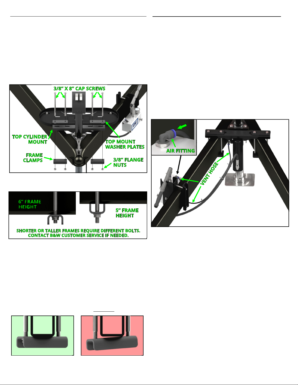
1 Head Unit 1
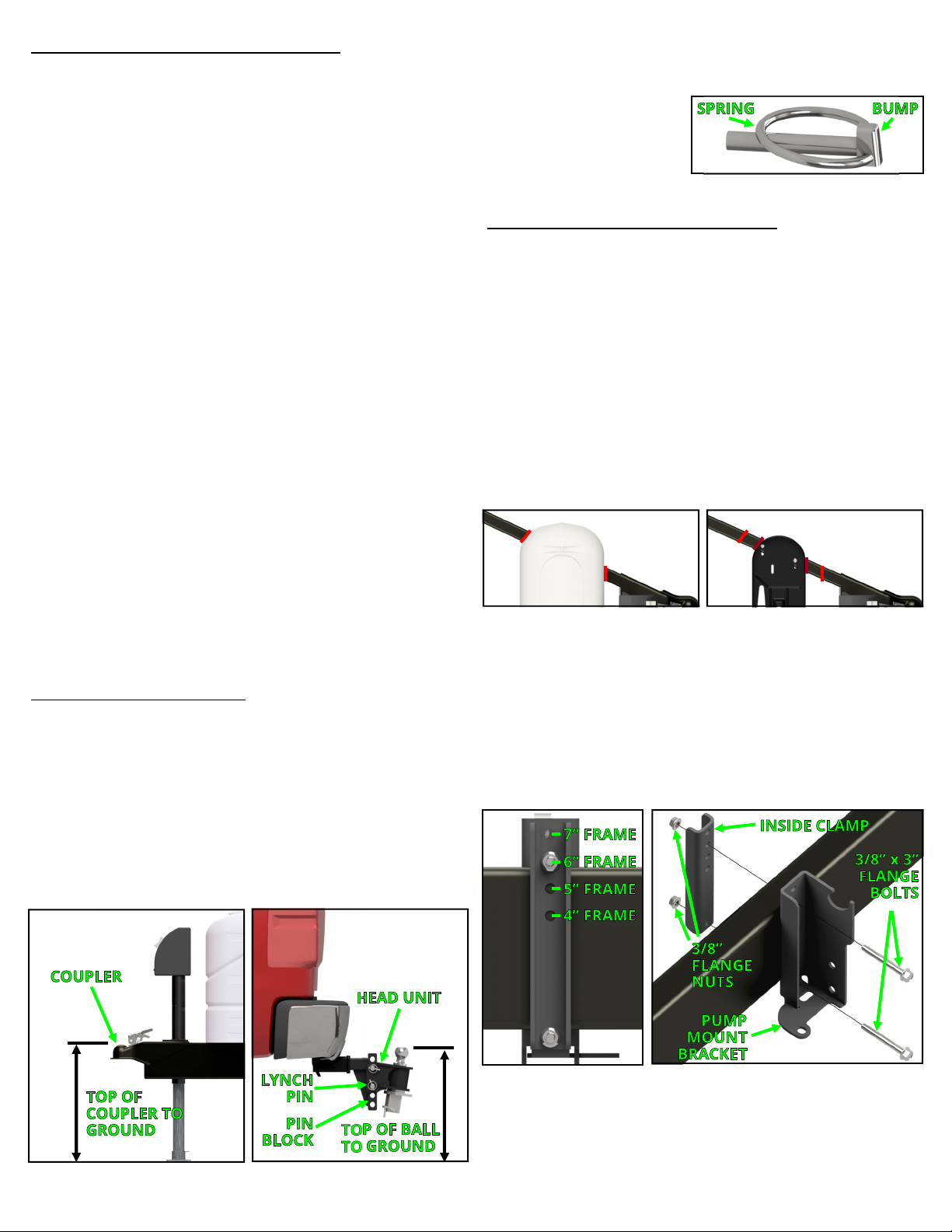
2 3/4” Receiver Pin w/ Cotter 1
BOLT BAG: 4210-200
# DESCRIPTION QTY
13 2” x 3” x 3/8” U-Bolt 1
14 3/8” x 8” Cap Screw 4
15 3/8” x 3/4” Flange Head Bolt 3
16 3/8” x 3” Flange Head Bolt 2
17 3/8” Flange Nut 8
1
4
3
5
6
10
While installation is being performed, check for signs of
damage or excessive corrosion. Do not install hitch
components over vehicle or trailer parts that are
broken or have compromised structural integrity.
Adding hitch components to the chassis of any vehicle
or trailer can be hazardous. There is potential for
unexpected combustion of fuel, electric shock, burns,
shifting or falling of unstable vehicle, damage to vehicle,
injury from tool usage and many other hazards. This
installation must be completed by someone who is
aware of the hazards involved. This person must be
knowledgeable of proper safety procedures for a
vehicle and trailer modification of this nature, and for
usage of the equipment required to perform the
installation.
Without proper knowledge, towing can be a dangerous
activity. Understand all the risks involved with towing
before proceeding. For information on towing safety,
see "The Trailer Handbook: A Guide to
Understanding Trailer and Towing Safety" from the
National Association of Trailer Manufacturers,
www.NATM.com and your trailer and tow vehicle
manufacturer's owner's manual.
Do not exceed tow or tongue rating of coupler, tow or
tongue rating of hitch, or tow or weight ratings of tow
vehicle or trailer. See vehicle and trailer manufacturer
information for ratings. Exceeding these ratings may
cause damage to towing components or loss of
attachment between the trailer and vehicle.
Do not modify this product in any manner. Doing so
could alter its integrity and lead to a loss of attachment
between the trailer and the tow vehicle.
A visual inspection of the towing components should be
performed before each use. Regularly check that all
connections are secure, including those that secure the
hitch to the vehicle. Check for cracks or damage to the
hitch, tow vehicle receiver, trailer coupler and frame.
Do not use the hitch if cracks or damage outside of
normal wear is found. Using a hitch that has unsecure
connections and/or cracks or damage could result in
damage to the tow vehicle, trailer, towing components
and loss of attachment between the tow vehicle and
trailer.
Failure to comply with the safety information in these
instructions could result in serious injury or death.
IMPORTANT SAFETY NOTICE FOR HITCH INSTALLERS AND CUSTOMERS.
Read all installation and operating instructions along with all labels before installing or using this product. Do not perform
any installation or towing procedures without fully understanding the correct tools and actions for all steps. Call B&W
Trailer Hitches Customer Service Department for support, if needed.
18
Follow all manufacturer instructions and warnings for
tow vehicle and trailer. The Continuum weight
distribution hitch is designed to work with vehicles and
trailers designed to use weight distribution hitches. Do
not use the Continuum hitch with any vehicle or trailer
that is not compatible for use with a weight distribution
hitch.
2
7
Continuum Hitch Components
BOX: WDHL4510* & WDHL4511
# DESCRIPTION QTY
3 Hydraulic Pump & Cylinder 1
4 Load Bar Assembly 1
5 Top Cylinder Mount 1
6 Pump Mount Bracket 1
7 Pump Mount Inside Clamp 1
8 Frame Clamp 2
9 Top Mount Washer Plate 2
10 Fork Holder Bracket 1
11 Top Cylinder Mount Pin 1
12 Cotter Pin 1
8 9
13
17
11
12
14
17
15
17
16
19 20
Extension kit (*not present in
WDHL4510 box)
# DESCRIPTION QTY
18 Hydraulic Cylinder Extension 1
19 3/4” x 4-1/4” Cap Screw 1
20 3/4” Lock Nut 1
Tire condition can influence trailer sway. Never tow
with tires that are under inflated, over loaded, or
damaged. These conditions will greatly lower the speed
at which the trailer will remain stable and may lead to
loss of control. Check tire condition before each tow.