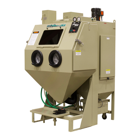
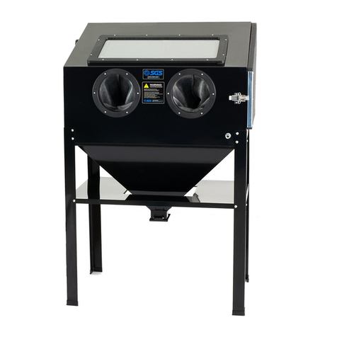
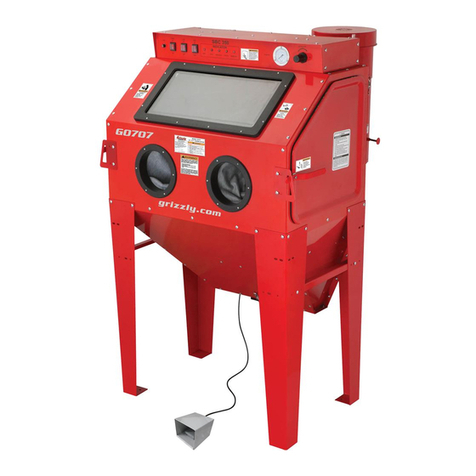
Contracor CAB-110P User manual

РУССКИЙ
DEUTSCHENGLISH
CONTRACOR GmbH
42329 Wuppertal
Germany
Art. 15205/15206
CAB-110P/CAB-135P
Blast Cabinets
INSTRUCTIONS
Version 3.9
Strahlkabinen
BEDIENUNGSANLEITUNG
Version 3.9
Seite 40
Кабина абразивоструйная
РУКОВОДСТВО
ПОЛЬЗОВАТЕЛЯ
Версия 3.9
стр. 79


ENGLISH
CONTRACOR®CAB-110P/CAB-135P Art. 15205/15206 3
Table of contents
1. Safety 4
2. Package and description 5
3. General information 9
4. Set-up, operation and shut-down 12
5. Maintenance 19
6. Troubleshooting 25
7. Replacement parts 29
ATTENTION!
READ AND FULLY UNDERSTAND THIS MANUAL BEFORE STARTING WORK.
THE FOLLOWING INFORMATION IS IMPORTANT FOR SAFETY AND HEALTH
OF OPERATOR AND PERSONNEL IN VICINITY.
ATTENTION!
BUYING THE MACHINE, PLEASE, REQUEST TO FILL IN THE GUARANTEE
CARD CORRECTLY!
FAILURE TO PRODUCE A FILLED-IN FORM WILL MAKE YOUR GUARANTEE
INVALID.

ENGLISH
CONTRACOR®Version 3.9
4
1. Safety
ATTENTION!
SAFETY MEASURES FOR BLAST CABINET OPERATION.
1. You must wear protective gloves during abrasive blasting.
2. Do not use worn or damaged equipment during operation.
3. Point the nozzle only at the area to be cleaned. Never point the nozzle
toward the cabinet windows.
4. Use only dry well-sieved abrasive materials, appropriate for abrasive
blasting operations.
5. Before starting of blast cabinet operation you must:
- Ensure that gloves, gaskets, hoses and ttings are not worn;
- Fix hose couplings with wire, if the couplings are used;
- Ensure that the cabinet is grounded;
6. During blasting process all doors on the cabinet, reclaimer or dust col-
lector must be closed.
7. After blasting, before the doors are opened and exhauster is switched
off, use the blow nozzle to blow media from the blasted parts.
8. Do not open the doors or switch off exhauster before the cabinet is
clear of abrasive dust.

ENGLISH
CONTRACOR®CAB-110P/CAB-135P Art. 15205/15206 5
2. Package and description
Picture 1. Cabinet componets overview CAB-110P/135P (Front view)
15 14
16
17
13
12
10
9
7
8
11
6
5
4
3
1
2

ENGLISH
CONTRACOR®Version 3.9
6
Picture 2. Cabinet componets overview CAB-110P/135P (Back view)
Pos. No Description
1 Conveying hose Ø 100
2Airline Filter
3Pressure regulator, pilot operated
19 1833
20212223
24
25
26
27
29
30
32
31
28

ENGLISH
CONTRACOR®CAB-110P/CAB-135P Art. 15205/15206 7
4Pressure gauge
5Air blow-off nozzle, rubber
6Rubber hose for air blow-off nozzle
7 Blast nozzle
8Nozzle holder
9Blast hose I.D. 19 mm
10 RGS Blast cabinet gloves
11 Cabinet door latch
12 Pressure regulator, working pressure
13 Panel mounting pressure gauge, working pressure
14 Double pushbuttons ON / OFF
15 Main switch 0-I
16 Viewing window (assembly)
17 Pneumatic foot pedal
18 Door interlock
19 Electric motor
20 Ventilation hose Ø 150
21 Diaphragm pulse-jet valve
22 Electronic timer for pulse-jet valve
23 Pressure regulator, pulse-jet cleaning
24 Pressure gauge
25 Pulse-jet cleaning manifold
26 Reclaimer assembly R-350 / R-400
27 Screen
28 Reclaimer door latch
29 Filter cartridge
30 Blast machine 25/50 liter
31 SGV metering valve
32 Dust container
33 Impeller for DC-1100 / 1500

ENGLISH
CONTRACOR®Version 3.9
8
Order code Model Description, package
15205 CAB-110P BLAST CABINET, COMPLETE SYSTEM, CONSIST
- Cabinet Enclosure
- Cyclone reclaimer R-350
- 25 liter blast machine
- Cartridge Dust Collector DC-1100
STANDARD DELIVERY:
- Quality 800 mm blast gloves with inner fabric lining
- 19x33 mm blast hose with coupling/nozzle holder
- Tungsten carbide venturi nozzle STC-6.5
- SGV metering valve
- Main airline ler with 5µ ltration grade
- Pilot regulated blast pressure
- Door safety interlocks
- Pulse cleaned cartridge lter 15 m²
Electrical connection 1,10 kW, 380V, 3 phase, 50Hz
Overall Dimensions (W x D x H) 1340 x 1220 x 1990
Working chamber size (W x D x H) 1100 x 800 x 840
Window size (Safety glass) 476 x 296
15206 CAB-135P BLAST CABINET, COMPLETE SYSTEM, CONSIST
- Cabinet Enclosure
- Cyclone reclaimer R-400
- 50 liter blast machine
- Cartridge Dust Collector DC-1500
STANDARD DELIVERY:
- Quality 800 mm blast gloves with inner fabric lining
- 19x33 mm blast hose with coupling/nozzle holder
- Tungsten carbide venturi nozzle STC-6.5
- SGV metering valve
- Main airline ler with 5µ ltration grade
- Pilot regulated blast pressure
- Door safety interlocks
- Pulse cleaned cartridge lter 20 m²
Electrical connection 1,50 kW, 380V, 3 phase, 50Hz
Overall Dimensions (W x D x H) 1470 x 1700 x 2140
Working chamber size (W x D x H) 1350 x 1100 x 1070
Window size (Safety glass) 476 x 296
2.1. Package
Table 2.1

ENGLISH
CONTRACOR®CAB-110P/CAB-135P Art. 15205/15206 9
3. General information
3.1. General information
Blast cabinet production rates depend upon the size of the nozzle, the capacity of the
compressor , the working pressure, the type and size of abrasive media and the distance
between the nozzle and the area to be cleaned.
Contracor pressure-type blast cabinets are made up of four main elements:
1. A robust, welded steel cabinet enclosure,
2. A cyclone reclaimer for best possible efciency in controlling media recycling,
3. A 25 or 50 liter blast machine with a durable SGV metering valve,
4. A dust collector consisting of a highly efcient fan and pulse-cleaned cartridge lter.
3.2. Theory of operation
When the air supply is on, and the cabinet doors are closed, the blast machine is
ready for operation by actuating the foot pedal. Only by fully depressing the pedal is the
machine pressurized and blast media are propelled through the nozzle.
After striking the object being blasted, the blast media, along with nes, dust, and
by-products generated by blasting, fall through the mesh work table into the cabinet hopper.
These particles are drawn into the reclaimer for separation.
Dust and nes are rst separated from the reusable blast media. Next, the media
is screened of oversize particles, and held in the reclaimer hopper for reuse. At the same
time, dust and nes are drawn through the reclaimer into the dry lter or dust collector,
which traps the dust and discharges clean air. By releasing the foot pedal the machine is
depressurized and blasting stops, allowing blast media to recollect in the machine.
The dust collector lter cartridge is cleaned by pulsation of high-velocity compressed
air expanding against the inner surface of the cartridge. An electronic timer controls the
intervals between the pulses. The expanding air momentarily reverses airow through the
cartridge to release dust which has gathered on the outer surface. The dust falls off of the
cartridge and into the hopper for later disposal.
ENGLISH
CONTRACOR®Version 3.9
10
Table 3.1 Max. nozzle size
3.4. Blast media
Contracor cabinets utilize most common media, 1,50 mm and coarser that is specically
manufactured for dry blasting.
The usable media mesh size and nozzle size are based on typical media ow. Rich media
ow or low static pressure will reduce the mesh and nozzle size that may be used.
3.3. Air jet diameter and required compressed air volume
The blast machine pressure vessel is manufactured according to European CE
regulations, as described in attached CE Certicate of conformity. The owner must ensure
and maintain the integrity of the vessel, as may be required in some countries.
Reclaimer type Max. nozzle size, mm
R-350 6,5
R-400 8,0
ATTENTION!
Excessive air pressure could cause the media chamber to rupture. To pre-
vent serious injury or death, do not exceed the rated pressure of the media
chamber vessel.
After having ensured that the air supply is activated and the cabinet doors are closed,
the media chamber can be actuated by the foot pedal. By pressing the foot pedal, the inlet
valve is opened and the outlet valve is closed, resulting in the cham-ber being pressurized
and the blasting beginning. By releasing the foot pedal, the chamber is depressurized and
blasting stops.
The standard nozzle delivered with the blast cabinet is a tungsten-carbide nozzle with
a 6.5mm orice. In addition, 5.0 and 8.0mm nozzles are available. The maximum diameter
of the orice under normal conditions is determined by the size of the reclaimer, as shown
in Table 3.1 below. Normal condition are moderate part contamination, media breakdown,
ow and size, and damper setting.

ENGLISH
CONTRACOR®CAB-110P/CAB-135P Art. 15205/15206 11
ATTENTION!
Abrasive blasting with sands containing crystalline silica can cause seri-
ous or fatal respiratory disease.
Steel blast media: : Still grit or shot can be limited used with CAB-110P and CAB-135P
cabinets (max. mesh size ca. 0,80 mm). Exact max. media mash is depended from materials
specic weight and grains geometry and should be determined with practical tests run by users.
Rubber curtains should be used to protect the cabinet walls from rapid wear .
Sand and Slag: Sand should never be used because of the respiratory hazards
associated with the use of using media containing free silica.
Slags are not recommended because they rapidly breakdown.
Aluminum Oxide, Silicon Carbide, and Garnet: Aggressive media such as these may
be used but consideration should be given to accelerated wear on any part of the cabinet,
reclaimer, nozzle and hoses which comes in contact with the media.
In case of using of an aggressive blast media a tungsten carbide nozzle have to be used.
Service life of the tungsten carbide nozzle lasts 10 to 20 times longer than ceramic.
Glass Beads: Most beads have been treated to ensure free-ow operation even under
moderately high humidity conditions. Glass beads subjected to excessive moisture may be
reused after thorough drying and breaking up of any lumps.
3.5. Compressed air quality
Condensed water from the compressed air is reduced by the air lter at the air inlet
connection. Use of the air lter is of particular importance in areas of high humidity or when ne-
mesh media are being used. Dampness can cause media to clot, restricting free ow through
the feed assembly. An air dryer may be necessary if moisture problems continue.
3.6. Compressed Air Requirements
The required air compressor capacity is determined by the blast nozzle size and pressure.

ENGLISH
CONTRACOR®Version 3.9
12
4. Set-up, operation and shut-down
4.1. Installation and Set-up
4.1.1 Location
Select a location where compressed air, water and electrical service are available.
Allow for full access to all doors and service areas and for efcient handling of large parts.
4.1.2 Compressed air supply line
Connect compressed air supply line with min. I.D. =1”. to the cabinet inlet. For
connection use a exible hose with same min. I.D. as the main airline. A smaller diameter
air supply line or hose may reduce blasting efciency.
4.1.3 Grounding
Ground the cabinet to prevent static electricity build up. For grounding attach an
external grounded wire to the grounding lug on the cabinet skirt.
ATTENTION!
Be certain that all pipe ttings and hose clamps are tight before using the
blast cabinet. Hose disconnection while under pressure could cause seri-
ous injury.
Table 3.2 Air Consumption
Ø
Blast nozzle
(mm)
REQUIRED AIR VOLUME (m³/min.)
at working pressure, bar
3456
5,0 0,7 0,8 0,9 1,0
6,5 1,3 1,5 1,7 1,9
8,0 2,0 2,5 2,0 3,3
NOTE: the above table shows only the air required for the blast nozzle. Additional air is
required for the air cartridge cleaning, which must be added to the above values.
The above values are valid for nozzles when new. As nozzle wear increases, so does the
air consumption, up to 70% to 80% more than when new.

ENGLISH
CONTRACOR®CAB-110P/CAB-135P Art. 15205/15206 13
ATTENTION!
Do not look into the reclaimer exhauster outlet while the exhauster is
turning. Injury to the eye or face could occur from objects being ejected
from the exhauster.
4.1.4 Electrical power connection
A wiring schematic is supplied with the cabinet. After wiring is completed, check the
motor rotation by momentarily turn switch on and off. The motor will slowly turn. Check
the rotation of the motor fan through the slots in the motor housing. The fan should rotate
clockwise when viewed from the fan end to the motor.
ATTENTION!
All electrical work must be carried out by a qualied electrician according
to the national and local standards.
4.1.5 Cabinet static pressure
Cabinet static pressure must be set to match the cabinet dimensions and reclaimer
sizes. Open the inlet damper further to decrease static pressure or close it further to
increase pressure.
Use the gloves as an indicator of right cabinet static pressure. With the exhauster on,
the gloves should be inated, but not elevated off the grate.
4.1.6 Foot pedal
Position the foot pedal on the oor at the front of the cabinet for easy accessibility.
Blast cabinet is designed for one-person operation. Be sure you can quickly remove your
foot from the pedal in an emergency.
4.2. Blasting operation
4.2.1 Media loading
With the exhauster off, add clean dry media, by pouring it into the reclaimer hopper
through the reclaimer door. Do not ll past the cone on the reclaimer.
Do not pour media directly into the cabinet hopper, as overlling may occur.

ENGLISH
CONTRACOR®Version 3.9
14
ATTENTION!
Always close cabinet, reclaimer and dust collector doors before blasting.
Keep all doors closed during blasting.
Always wear blast gloves.
Avoid pointing the blast nozzle toward the view window.
Use the blow-off nozzle to blow media off parts before opening doors.
After blasting, keep doors closed and exhauster on until the cabinet is
clear of all airborne dust.
Stop blasting immediately if dust leaks are detected.
Overlling will result in media carryover to the dust collector and possibly blockage in the
conveying hose. Rell only after all media has been recovered from the cabinet.
Table 4.1 The minimum amount of media to charge the system is as follows
CAB-110P CAB-135P
20 kg 40 kg
4.2.2 Unloading Media
To empty media out of the blast cabinet, pressure must rst be reduced to 3bar. Then
place an empty container on the grate of the cabinet. Remove nozzle and washer from
nozzle holder, close the door and choke valve, and depress the foot pedal.
Media ow is to be directed into the container until full. Repeat as often as necessary
until the machine is empty. Whilst handling the container, local Operational Health and
Safety regulations are to be observed. When the machine is empty, return the choke valve
to the fully open position. Inspect and clean the threads on nozzle holder and nozzle before
reinstalling nozzle washer and nozzle.
4.2.3 Parts loading and unloading
Parts may be loaded and unloaded through either door. Blasted parts must be free of
oil, water, grease, or other contaminants that will clog media or lters. By closing the door,
be certain that the door is sealed securely or door interlock system will prevent blasting.
4.2.4 Blasting operation

ENGLISH
CONTRACOR®CAB-110P/CAB-135P Art. 15205/15206 15
ATTENTION!
Shut down the cabinet immediately if dust discharges from the collector.
Check that lters are correctly seated and not worn or damaged.
Prolonged breathing of any dust could result in serious lung disease
or death. Short term ingestion of toxic dust such as lead, poses an
immediate danger to health. Toxicity and health risk vary with dust
generated by blasting. Identify all material being removed by blasting, and
obtain a material safety data sheet for the media.
Turn on the compressed air supply to the blast cabinet. Inspect for air leaks during
the initial start up
Set the pulse pressure regulator to 4,5 bar (see Picture 2 for location).
Turn the on/off switch to t “I” to activate the lights and lter pulse cleaning.
Push the “ON” button to turn on the exhauster.
Put on the rubber gloves.
Grasp the blast nozzle rmly and step on the pedal. Blasting will start immediately.
Set blast pressure using the pilot regulator located on the control panel.
The pressure gauge on the control panel indicates the actual blast pressure.
Smooth, continuous strokes are the most effective blasting technique. The size of
the blast pattern is affected by the distance from the part. The nozzle is usually positioned
approximately 70 to 150mm from the surface of the part.
The dust collector pulsates automatically according to the timer settings while
the blast cabinet is in operation. Prolonged periods of blasting or dirty conditions may
necessitate an adjustment of the timer settings.
4.2.5 Stop blasting operation and shut-down
To stop blasting, remove pressure on the foot pedal.
Use the Air blow-off nozzle to blow media off cleaned parts. Allow the exhauster to
clean the cabinet of airborne dust before opening the door and unload the parts.

ENGLISH
CONTRACOR®Version 3.9
16
Picture. 3. Metering valve adjustment
Push button OFF to switch off the exhauster.
Turn on/of switch to the position “0” to switch off the lights and lter pulse cleaning.
Shut off the air supply to the blast cabinet and drain air lter.
4.3. Adjusting
4.3.1 Blasting pressure
The pilot pressure regulator, located on the control panel of the cabinet, enables the
user to adjust the blasting pressure to suit the application.
The suitable pressure for most purposes is around 5-6 bar. Lower pressures may be
required on delicate substrates, and will reduce media breakdown. Higher pressure may be
required for difcult blasting jobs on durable substrates, but will increase media break down.
In all cases, highest production can only be achieved when pressure is carefully monitored.
Adjust air pressure by turning the knob on the pilot regulator located on the front of
the control panel. Pull the knob out, and turn clockwise to increase pressure or counter-
clockwise to decrease. Once operating pressure is set, push the knob in to lock.
4.3.2 Media metering
Media volume ow is adjusted
by the metering valve at the
foot of the blast machine. Close
metering valve SGV by rotating the
handle clockwise. To increase the
ow of media, rotate the handle
counterclockwise. Wait for the
ow to stabilize before further
regulation. The maximum ow rate
is reached when the handle is in
the full left position. Adjust ow
rate according to type and size of
blast media, blasting pressure, and
the task at hand, ensuring to use
as little media as possible whilst
still maintaining a high cleaning Adjusting handle

ENGLISH
CONTRACOR®CAB-110P/CAB-135P Art. 15205/15206 17
ATTENTION!
Never attempt to override the interlock system.
Doing so could result in injury from unexpected blasting.
pace. The correct mixture of air and abrasive can generally be distinguished by a slight
discoloration at the exit of the nozzle.
4.3.3 Reclaimer static pressure
Correct static pressure varies with size of reclaimer and the size, weight and type of
media. Adjust reclaimer static pressure by opening (handle horizontal) or closing (handle
vertical) the damper on the dust collector inlet.
If the damper is not opened enough, the reclaimer will not remove nes, resulting
in dusty media, poor visibility, and possible media blockage in the conveying hose. If the
damper is opened too far, it may cause carryover (usable media carried into the dust
collector) and result in excessive media consumption. Open only as far as necessary to
obtain a balance of dust removal without media carryover.
4.3.4 Cabinet static pressure
Once the inlet is initially set per section 4.1.5, it seldom requires readjustment.
The initial setting produces approximately 50% to 75% of static pressure in the cabinet
enclosure. For adjustment open the inlet damper further to decrease static pressure or
close it further to increase pressure.
Use the gloves as an indicator of right cabinet static pressure. With the exhauster on,
the gloves should be inated, but not elevated off the grate.
4.3.5 Door Interlocks
The door interlocks disable the blasting control circuit when the doors are open. To enable
blasting, the door interlock switches must be engaged when the doors are closed. The interlocks
are set at the factory and do not usually require eld adjustment unless parts are replaced.
To adjust the actuator, bend it by hand as required for engaging the switch by full
closed door.

ENGLISH
CONTRACOR®Version 3.9
18
Picture 4. Actuator adjustment
Interlock
switch
Cabinet door
Actuator
Test the operation with the doors both open and closed. Point the nozzle away from
the door when it is tested, and only open the door enough to disengage the interlock switch.
The interlocks should stop the blasting when the doors are opened, and permit blasting
when the doors are closed.
NOTE: Negative pressure inside the cabinet may cause the doors to ex inward. Tests
should be performed with the exhauster on.
4.3.6 Pulse pressure
Adjust pulse pressure using the regulator mounted on the pulse manifold. Begin pulse
pressure setting at 4,5 bar.
When pulsing alone does not adequately clean the cartridge, increase pulse pressure
by 0,5 bar increments up to max. 6,0 bar. Increasing pulse pressure over 6,0 bar may cause
damaging of the cartridge lter.
If after pressure increasing, dust cakes on the cartridges and differential pressure
increase, adjust cycling of the pulses.

ENGLISH
CONTRACOR®CAB-110P/CAB-135P Art. 15205/15206 19
Picture 5.Pulse time and cycling
adjustment
5. Maintenance
5.1. Preventive Maintenance
5.1.1 SGV Metering Valve
The SGV metering valve must be regularly inspected for wear. To prolong the life of the
valve, inspect the internal rubber lining regularly for wear and replace when necessary.
5.1.2 Dust container
Empty the dust container regularly. Start by checking the container at least daily or when
adding media, then adjust frequency based on usage, contamination and friability of the media.
4.3.8 Timer
Adjust pulse time and cycling on the timer (see Picture 2 for location).
Use ON scale to adjust the pulse length and OFF scale to adjust the time period
between the pulses.
Begin setting is as follows:
Pulse length (ON scale) - 60 ms (by 4.5 bar pulse pressure)
Time between pulses (OFF scale) - 5 min

ENGLISH
CONTRACOR®Version 3.9
20
5.1.3 Reclaimer debris screen
The screen is accessible through the reclaimer door. With the exhauster off, remove the
screen and empty it daily or when loading media. Empty the screen more often if parts being
blasted causes excessive debris. Do not operate the machine without the screen in place.
5.1.4 Airline lter
The cabinet is equipped with a manual drain airline lter.
Drain the airline lter at least once a day, more often if required, or if water mist is seen
coming out the nozzle.
Moist air inhibits the ow of media. If moisture continues to be present, a refrigerated
air dryer may be required.
5.1.5 Media Hose
To avoid unscheduled down-time, inspect the media hose for thin spots, especially
along an outside radius.
5.1.6 Blast Hose and Couplings
Check blast hose for excessive wear, particularly on the outside radius, to prevent
punctures. Check couplings and coupling gaskets for leakage and wear.
5.2. Service maintenance
5.2.1 Gloves
Special static-dissipating gloves have been provided for operator comfort. It will be
necessary to change gloves periodically as they wear. The rst sign of deterioration may
be excessive static shocks. Gloves are held in place by metal clamps on the inside of the
cabinet. To replace, loosen the clamps with a screwdriver, replace the gloves, and tighten the
clamps.
5.2.2 Nozzle
The nozzle should be replaced when its diameter has increased by a maximum of 2mm
(or earlier if pressure diminishes signicantly).
This manual suits for next models
3
Table of contents
Other Contracor Shot Blasting Machine manuals

Contracor
Contracor BlastRazor Z-100RC User manual

Contracor
Contracor DBS-100 User manual

Contracor
Contracor DBS-25RC User manual

Contracor
Contracor DBS-100RC User manual

Contracor
Contracor BlastRazor Z-25RC User manual

Contracor
Contracor BlastRazor Z-100RCS User manual

Contracor
Contracor CAB-110S Operating instructions