Contracor DBS-100RC User manual

CONTRACOR GmbH
42329 Wuppertal
Germany
Abrasive Blasting Machines DBS-100RC DBS-200RC
OPERATION MANUAL
Version 2.5
Sandstrahlmaschinen DBS-100RC DBS-200RC
BEDIENUNGSANLEITUG
Version 2.5
Seite 19
DBS-100RC DBS-200RC
EN
DE
RU
Art. 10301/10401


3
CONTRACOR®DBS-RC Art.10301/10401
Contents
1. Safety 4
2. Package and description 5
3. Set-up, operation and shut-down 6
4. Abrasive blasting operations 8
5. Maintenance 10
6. Troubleshooting 11
12
8. Instructions for Use Pressure Vessel of Abrasive Blasting Machine
CONTRACOR DBS
14
ATTENTION!
READ AND FULLY UNDERSTAND THIS MANUAL BEFORE STARTING WORK. THE
FOLLOWING INFORMATION IS IMPORTANT FOR SAFETY AND HEALTH OF OPERATOR AND
PERSONNEL IN VICINITY
ATTENTION!
BUYING THE MACHINE, PLEASE, REQUEST TO FILL IN THE GUARANTEE CARD CORRECTLY!
FAILURE TO PRODUCE A FILLED-IN FORM WILL MAKE YOUR GUARANTEE INVALID.

4CONTRACOR®Version 2.5
1. Safety
ATTENTION!
SAFETY MEASURES FOR ABRASIVE BLASTING.
1. You must wear protective equipment: a helmet with positive air feed, breathing air
2. Do not use worn or damaged equipment during operation.
3. Point the nozzle only at the area to be cleaned.
4. Use only dry well-sieved abrasive materials, appropriate for abrasive blasting
operations.
4. Use only dry well-sieved abrasive materials, appropriate for abrasive blasting
operations.
6. Before starting abrasive blasting operations you must:
— Ensure that the machine is in steady state position

5
CONTRACOR®DBS-RC Art.10301/10401
2. Package and description
Fig. 2.1

6CONTRACOR®Version 2.5
2.1 Package
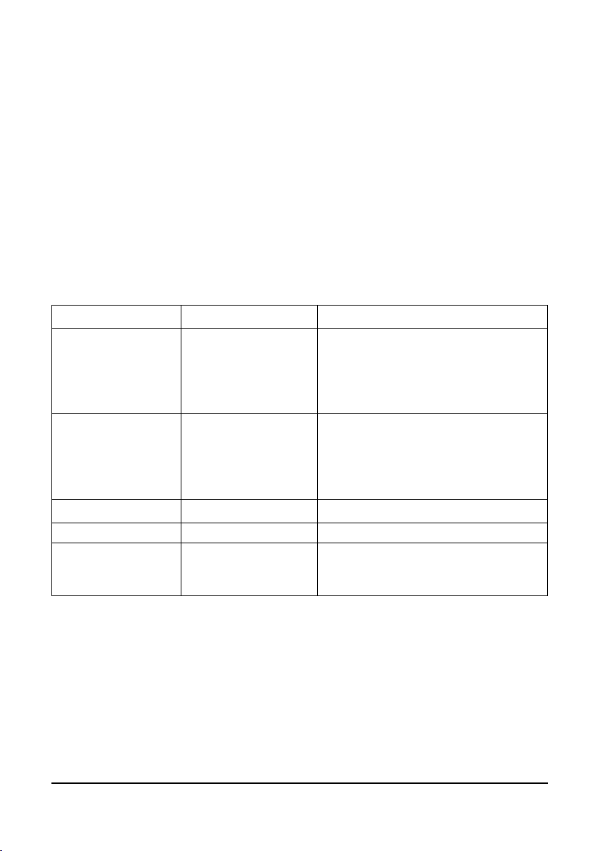
Article Model Description, package
10301 DBS-100RC
Abrasive Blasting Machine, 100 L, screen,
1, remote control unit RCV, remote control
handle DMH, abrasive metering valve FSV,
RC hose.
10401 DBS-200RC
Abrasive Blasting Machine, 200l, screen,
1, remote control unit RCV, remote control
handle DMH, abrasive metering valve FSV,
RC hose.
RCV Remote control valve (5, Fig.2.1)
10880 DMH Remote control handle (11, Fig.2.1)
12103 TWINLINE
Remote control twin hose, d=6mm, roll 40 m
(4, Fig.2.1)
3. Set-up, operation and shut-down
3.1 Preparation for operation
For remote control system start up you should follow these instructions:
1 — Cover
2 — Screen
3 — Machine tank
4 — RC hose TWINLINE
5 — Remote control unit RCV
6 — Moisture and oil separator CAF-1
8 — Operator helmet COMFORT
9 — Nozzle holder
10 — Nozzle
11 — RC handle DMH
12 — Breathing air hose
14 — Safety ball valve

CONTRACOR®DBS-RC Art.10301/10401
1. If necessary shorten the RC hose to the length of the used blasting hose.
distant control handle DMH from one side and TWINLINE line of the blasting machine from
another side.
ATTENTION!
DO NOT TIGHTEN UNIONS TOO MUCH, IN PARTICULAR THE UNIONS OF RC HANDLE. IT
CAN DAMAGE SOME COMPONENTS AND CAUSE AN AIR LEAK.
3. Ensure that all connections are leak-proof.
4. Ensure that all connections on the RC valve and RC handle DMH are connected
properly, and according to the color. Transverse joint will make the system non-
operational.
5. Fix RC handle DMH to the blasting hose, using clamp bands right behind the nozzle
holder.
6. We recommend to connect a twin hose Twinline to the blasting hose using clamp bands
every 1.5 m.
ATTENTION!
ALWAYS USE AN OIL-MOISTURE SEPARATOR WHEN USING REMOTE CONTROL SYSTEM TO
PREVENT WEAR ON RC VALVE.
BESIDES, AN OIL-MOISTURE SEPARATOR OPTIMIZES ABRASIVE BLASTING OPERATIONS.
downwind side.
8. Start compressor and increase pressure and temperature up to operational values.
9. Open the ball valve at machine compressed air line (the handle of the open valve
should be parallel to the compressed air line).
10. Open the safety ball valve 14 (Fig.2.1).
11. Close metering valve FSV by setting adjusting handle in the central position.
12. Connect compressed air hose to hose coupling of the machine. Compressed air hose
diameter should be at least 1.1/4”. Lock hose coupling with a safety clip or wire.

8CONTRACOR®Version 2.5
13. Connect abrasive blasting hose to hose coupling of the machine. Lock hose coupling
with a safety clip or wire.
14. Fill the machine tank with abrasive.
15. Put protective equipment on.
4. Abrasive blasting operations
4.1 Start up
1. Check all connections from compressor to the nozzle to ensure that they are properly
3. Ensure that the necessary safety measures for you and others are observed:
— protective equipment is used,
4. Always check position of RC handle lever, which should be in the safety position with the
holder in vertical position
5. Feed compressed air to the machine intake.
ATTENTION!
6. Close both ball valves at the RC valve.
the RC handle lever.

9
CONTRACOR®DBS-RC Art.10301/10401
4.2 Abrasive blasting operations
ATTENTION!
DURING A BREAK IN OPERATION ALWAYS OPEN SAFETY BALL VALVE 14 (Fig. 2.1) AT RC
VALVE, OVER AGAINST THE BLUE LINE OF TWIN HOSE (TWINLINE).
CAUSE A SERIOUS INJURE..
1. Turn the holder on RC handle and press the lever (start up). The tank is pressurized.
Only compressed air is expelled from the nozzle.
2. Adjust metering valve FSV to provide optimal air-abrasive mixture. The general rule for
abrasive blasting operations: the less abrasive you use, the better.
3. To stop operation you should release the lever (the holder automatically returns to its
initial position).
4.3 Shut-down abrasive blasting operations
1. Remove the remains of abrasive from the tank. To do this disconnect the nozzle and
point the hose into a suitable container for the abrasive remains. Turn the holder on the
RC handle and press the lever.
2. If upon completion of operation the machine is left outside you should cover it with
ATTENTION!
AT START UP AND SHUT DOWN ALWAYS CHECK FOR PRESENCE OF WATER IN THE RCV
PRESENT, CHECK THE FILTER CAF-3.

10 CONTRACOR®Version 2.5
5. Maintenance
5.1 Machine maintenance
Pressurizing valve replacement.
Open the inspection door of the machine to get access to the pressurizing valve. Screw out
the guide tube with the valve inside. Install a new valve and screw the guide tube back into
its place.
Pressurizing valve ring replacement.
into the groove and press it heavily to correct position.
ATTENTION!
USE ONLY ABRASIVE MATERIALS, APPROPRIATE FOR ABRASIVE BLASTING OPERATIONS.
NEVER USE WET UNSIFTED ABRASIVE MATERIALS.
5.2 Daily maintenance
state.
2. Ensure that the rubber insert of the RC handle is in proper condition. If they look bad or
are worn, replace them, to avoid possible damage.
5.3. Monthly maintenance (or after every 160 operation
hours)
2. Ensure that there is no leak in all air connections.
3. Dismantle the control valve following RCV User Manual and check all moving parts. If
they look worn, replace them, to avoid possible damage. Assemble the valve and lubricate
its moving parts with general purpose lube oil.

11
CONTRACOR®DBS-RC Art.10301/10401
6. Troubleshooting
Choking.
If neither abrasive, nor air comes out of the nozzle, relieve pressure and depressurize the
machine, then ensure that the nozzle is not choked. If only air without any abrasive comes
out of the nozzle, fully open the metering valve, and then quickly close and open again
the lower ball valve of the line. If these actions do not help to relieve the pressure in the
machine, open the inspection door and ensure that there is no foreign matter in the tank
(stones, paper, etc.).
Abrasive surges.
During start-up of the machine abrasive surges are normal to a certain degree. However
opening of the line lower ball valve. Abrasive surges often result from elevated moisture
content in compressed air system. Installation of additional moisture and oil separator can
solve this problem.
Wet abrasive removal.
To remove wet abrasive from machine tank you should disconnect the blasting hose and
remove rubber gaskets at machine hose coupling. Then you must fully open the metering
valve and close the lower ball valve in the machine compressed air line. With such valve
of the tank.
6.1 RC system troubleshooting
The following list of checks can be used for determining problems in case the RC system
does not function properly:
1. Study RCV User Manual
2. Visually check all air hoses and connections to ensure that there are no air leaks.
3. Ensure that the safety and drain valve are closed.
4. Check the RC handle for air leaks:
— when the key is not depressed, the air should come only out of the body vent.
— when the key is depressed no air should come out of the handle.

12 CONTRACOR®Version 2.5
Problem Cause Solution
Air does not come out of
the vent in the RC handle
body.
Twinline hose is clogged or
pinched.
Disconnect the Twinline hose and ensure that
it is not clogged.
Control valve RCV does
not open.
Safety drain valve is still
open.
Close the safety drain valve.
Air feed to abrasive
blasting machine is not
Dismantle the control valve, all
parts should rotate freely.
RC control valve RCV
does not close.
RC handle channels are
clogged.
Remove the key and clean it.
Incorrect connection of
TWINLINE hose.
Check connections and change them if they
are incorrect.
Control valve failure. Disassemble the valve and ensure that it
functions properly.

13
CONTRACOR®DBS-RC Art.10301/10401
Pos. Description Quantity
DBS-
100RC
DBS-
200RC
1 10900 Hose coupling, CFT 2 2
210911 Nipple 1 1/4” (MM), rubberized 6 6
3 10930 Oil-Moisture separator, CAF-3 1 1
4 Remote control unit RCV 1 1
510915 Union with a cap nut, straight , 1 1/4”, (FM) 3 2
6 10909 Elbow, 90°, 1 1/4” (FM) 1 1
10910 T-piece, 90°, 1 1/4”, (FFF) 1 1
8 10942 Ball valve, 1 1/4”, (MM) 1 1
910913 Union with a cap nut, straight , 1 1/4”, (FF) — 1
10 10914 Pipe 1 1/4” — 1
11 10916 Elbow, 45°, 1 1/4” (FF) 1 1
12 10918 Pipe 1 1/4”, (MM) 390 mm for DBS-100 1 —
— 1
13 10919 Elbow, 45°, 1 1/4” (FM) 1 1
14 10990 Y-piece, 45°, 1 1/4”, (FFF), rubberized 1 1
15 10921 Pipe 1 1/4”, (100mm), rubberized 1 1
16 10850 Abrasive metering valve, FSV 1 1
10994 Pipe 1”, (MM) 190 mm for DBS-100 1 —
10952 Pipe 1”, (MM) 260 mm for DBS-200 — 1
18 10953 Elbow 90°, 1”, (FF) 1 1
19 10993 Pipe 1”, (M) 165 mm for DBS-100 1 —
10954 Pipe 1”, (M) 190 mm for DBS-200 — 1
20 10955 Guide 1 1
21 10960 Pressurizing valve 1 1
22 10950 Pressurizing valve seat 1 1
23 10932 DBS tank service assembly, kit 1 1
24 10935 Screen 1 —
10936 Screen — 1
25 10933 Tank cover 1 —
10934 Tank cover — 1
10956 Elbow, 90°, 3/4” (MF) 2 2
28 10958 Pipe 3/4” 1 1
29 Union with a cap nut, straight, 3/4” (FF) 1 1
31 10828 RC Ball valve, 1/4” 2 2

14 CONTRACOR®Version 2.5
33 10922 Wheel 2 —
10923 Wheel — 2
34 10830 Extension for DBS-100 RC/RCS 1 —
10844 Extension for DBS-200 RC/RCS — 1
8. Instructions for Use Pressure
Vessel of Abrasive Blasting Machine
CONTRACOR DBS.
8.1 Technical Parameters
Vessel Type DBS — 100 — 10 DBS — 200 — 10
Volume V (L) 100 200
Calculated Pressure P (Bar) 10 10
Maximum Working Pres- sure PS (Bar) 10 10
Maximum Test Pressure PT (bar) 14,3 14,3
Minimal Operating Tempe- rature TSmin (°C) -10 -10
Maximum Operating Tem- perature TSmax (°C) 50 50
Corrosion charge c2(mm) 0,5 0,5
Media air + abrasive ma-
terials
air + abrasive ma-
terials
8.2 Field of Application
The pressure vessels are intended for use only with the media and within the parameters
stated in the table above. The use for any other purpose is not allowed.
8.3 Set Up and Installation
1. The vessels can be set up indoors or outdoors under a roof.
media used, must be observed when choosing a place for setup. When set up outdoors,
the minimal and maximum working temperatures must be observed.

15
CONTRACOR®DBS-RC Art.10301/10401
accessible for inspections, tests, maintenance and cleaning, from the inside and the
outside.
The type plate has to be accessible and kept clean so that it is readable at all times.
3. The main body is based on supports, stands or feet suitable for the strain of the
pressure test. The vessel must be set up on foundations with a stability suitable for the
strain of the pressure test.
8.4 Setting the Vessel to Work
A. Conditions for setting the vessel to work.
1. The vessel can be set to work, including test operation, if:
— its condition does not pose a danger to people and environment,
— the system and equipment is complete, tested and meets the requirements
according to the documentation and applying standards.
B. Procedure before start up of the machine
2. Before closing the vessel make sure that there is no foreign matter or object inside.
the bolts are inserted correctly in place and of the right length and tightened to the correct
torque.
C. Start up Procedure.
4. If not stated otherwise in the instructions for the start up of the vessel, the control valve
must open in such a way that the pressure does not rise more than 5 bar per minute and
the temperature does not exceed the value stated for the start up of the vessel. Avoid
sudden changes in pressure or temperature as they can cause unfavou- rable tension.
problem occurs, e.g. leaks or cracks, the vessel has to be closed down immediately.
6. During transport vessels must not be under pressure and they must not contain
media.
D. Operation of the vessels.
8. The vessel must be closed down immediately,

16 CONTRACOR®Version 2.5
— if cracks appear,
— if there is a leak in a connection that can be disassembled,
— if there is a safety-equipment failure or defect (e.g. clogging of the safety valve) or a
failure of the level meter etc.,
— when there is immediate danger of an accident or a problem if operation continue,
— if any other unusual phenomena occur during operation whose causes cannot be found
or eliminated,
— if a deformation on the vessel wall occurs,
— if the temperature exceeds the maximum working temperature,
— in all cases stated in the manual that advise the operator to do so.
8.5 Operating the Vessel
1. Only persons meeting the following requirements are allowed to operate the vessel:
— The person is of age and able to do such work,
— The person knows the applying regulations and rules for the operation of the vessel well,
has been trained practically and has passed a corresponding exam which is documented
A. Duties and responsibilities of the operator
2. The person appointed to operate the vessel is obliged to:
— know all facilities and equipment securing a safe operation, and their use, well and be
able to react appropriately in unusual circumstances to restore safety,
— report every problem, damage or unusual incidents, occurring during operation of the
vessel or its attachments, to his superior immediately and close down the vessel if further
operation could be dangerous,
— take part in checks and inspections of the vessel, so that he knows the condition of the
vessel,
— check and test the equipment as recommended,
— document the operation according to the regulations,

CONTRACOR®DBS-RC Art.10301/10401
B. Vessel Inspections and Tests
3. The vessels have to be subjected to the following tests and inspections:
— External inspection during operation,
— Inspection of interior,
— Leak test,
— Pressure test, the tests must be conducted according to the applying regulations for the
use of pressure equipment of the respective country that the vessel is used in.
C. Documentation of Inspections.
with the user and available during the whole period of use of the vessel.
8.6 Cleaning and Maintenance of Vessels
1. The cleaning method and media have to be in such a way that they do not to damage
the walls of the vessel or endanger the workers.
2. The vessel must be cleaned inside and outside and it must be covered with a suitable
3. Only specially trained and experienced persons are allowed to work on the vessel and
the system components, including the safety equipment. They have to be appointed with
8.7 Repair of Vessels.
It is not allowed to weld or work on the parts of the vessel that are subject to pressure. Only
authorized organizations are allowed to install or repair the vessels.


19
CONTRACOR®DBS-RC Art. 10301/10401
Inhalt
1. Sicherheit 20
2. Ansicht Arbeitsaufbau 21
3. Aufbau, Betrieb und Beenden der Arbeit 22
4. Durchführung von Strahlarbeiten 24
5. Wartung 26
6. Fehlerbehebung
Übersichtszeichnung 29
8. Bedienungsanleitungder Druckbehälter des Strahlgerätes CONTRACOR
DBS
31
ACHTUNG!
BITTE LESEN SIE DIESES HANDBUCH VOR GEBRAUCH DER MASCHINE GENAU DURCH:
DIE FOLGENDEN INFORMATIONEN SIND WICHTIG FÜR DIE SICHERHEIT UND
GESUNDHEIT DES ANWENDERS UND PERSONEN, DIE SICH IN DER NÄHE AUFHALTEN.
ACHTUNG!
ACHTEN SIE BEIM KAUF DER MASCHINE BITTE DARAUF, DASS DIE GARANTIEKARTE
VOLLSTÄNDIG AUSGEFÜLLT WIRD.
WENN DIE KARTE NICHT AUSGEFÜLLT VORLIEGT, BESTEHT KEIN GARANTIEANSPRUCH.

20 CONTRACOR® Version 2.5
1. Sicherheit
ACHTUNG!
SICHERHEITSREGELN FÜR STRAHLARBEITEN.
einen Schutzanzug, Lederhandschuhe, und spezielles Schuhwerk.
2. Benutzen Sie keine abgenutzte oder beschädigte Ausrüstung.
3. Richten Sie die Düse nur auf den zu bearbeitenden Bereich.
4. Verwenden Sie nur geeignete, trockene und gut durchgesiebte Strahlmaterialien.
5. Alle Personen ohne Schutzausrüstung müssen außerhalb des Arbeitsbereiches
bleiben.
6. Bevor Sie mit der Strahlarbeit beginnen, müssen Sie folgendes beachten:
— Stellen Sie sicher, dass Schläuche und Verbindungen unbeschädigt und nicht
— Überprüfen Sie den festen und sicheren Stand der Maschine.
This manual suits for next models
3
Table of contents
Languages:
Other Contracor Shot Blasting Machine manuals

Contracor
Contracor BlastRazor Z-25RC User manual

Contracor
Contracor DBS-100 User manual

Contracor
Contracor CAB-110S Operating instructions

Contracor
Contracor CAB-110P User manual

Contracor
Contracor BlastRazor Z-100RC User manual

Contracor
Contracor DBS-25RC User manual

Contracor
Contracor BlastRazor Z-100RCS User manual