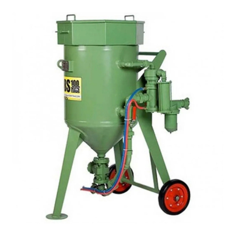
Contracor BlastRazor Z-100RC User manual

CONTRACOR GmbH
42329 Wuppertal,
Germany Art. 10400101/10400201
Abrasive Blasting Machines
BlastRazor Z-100RC, BlastRazor Z-200RC
OPERATION MANUAL
Version 1.7
EN
DE
Sandstrahlmaschinen
BlastRazor Z-100RC
BlastRazor Z-200RC
BEDIENUNGSANLEITUNG
Version 1.7
Seite 15
RU
Аппараты абразивоструйные
BlastRazor Z-100RC
BlastRazor Z-200RC
РУКОВОДСТВО ПО ЭКСПЛУАТАЦИИ
Версия 1.7
стр. 28

2CONTRACOR® Version 1.7
Contents
1. Safety 3
2. Package and description 4
3. Set-up, operation and shut-down 6
4. Abrasive blasting operations 7
5. Maintenance 9
6. Troubleshooting 10
7. Specication 12
ATTENTION!
READ AND FULLY UNDERSTAND THIS MANUAL BEFORE STARTING WORK. THE
FOLLOWING INFORMATION IS IMPORTANT FOR SAFETY AND HEALTH OF OPERATOR AND
PERSONNEL IN VICINITY
ATTENTION!
BUYING THE MACHINE, PLEASE, REQUEST TO FILL IN THE GUARANTEE CARD CORRECTLY!
FAILURE TO PRODUCE A FILLED-IN FORM WILL MAKE YOUR GUARANTEE INVALID.

3
CONTRACOR®BlastRazor Z-100RC/BlastRazor Z-200RC Art.10400101/10400201
1. Safety
ATTENTION!
SAFETY MEASURES FOR ABRASIVE BLASTING.
1. You must wear protective equipment: a helmet with positive air feed, breathing air
lter, protection suit, leather gloves, and special footwear.
2. Do not use worn or damaged equipment during operation.
3. Point the nozzle only at the area to be cleaned.
4. Use only dry well-sieved abrasive materials, appropriate for abrasive blasting
operations.
4. Use only dry well-sieved abrasive materials, appropriate for abrasive blasting
operations.
6. Before starting abrasive blasting operations you must:
— Ensure that hoses and ttings are not worn;
— Fix hose couplings with wire;
— Ensure that air is fed to the helmet;
— Ensure that pressurizing valve is in correct position;
— Ensure that the machine is in steady state position

4CONTRACOR® Version 1.7
2. Package and description
8
2
13
14
4
5
1
3
6
7
9
11
10
12
Fig. 2.1

5
CONTRACOR®BlastRazor Z-100RC/BlastRazor Z-200RC Art.10400101/10400201
2.1 Package
Article Model Description, package
10400101 BlastRazor-100RC Abrasive Blasting Machine, 100 L, screen,
cover, moisture and oil separator lter CAF-
1, remote control unit RCV, remote control
handle DMH, abrasive metering valve FSV,
twin hose in RC TWINLINE 20m, tting set for
RC hose.
10400201 BlastRazor-200RC Abrasive Blasting Machine, 200l, screen,
cover, moisture and oil separator lter CAF-
1, remote control unit RCV, remote control
handle DMH, abrasive metering valve FSV,
RC twin hose TWINLINE 20m, tting set for
RC hose.
10110870 RCV Remote control valve (5, Fig.2.1)
10110880 DMH Remote control handle (11, Fig.2.1)
10112106 TWINLINE Remote control twin hose, d=6mm, roll 40 m
(4, Fig.2.1)
1 — Cover
2 — Screen
3 — Machine tank
4 — RC hose
5 — Remote control unit
6 — Moisture and oil separator
7 — Abrasive blasting hose
8 — Operator helmet
9 — Nozzle holder
10 — Nozzle
11 — RC handle
12 — Breathing air hose
13 — Breath air lter
14 — Safety ball valve

6CONTRACOR® Version 1.7
3. Set-up, operation and shut-down
3.1 Preparation for operation
For remote control system start up you should follow these instructions:
1. If necessary shorten the RC hose to the length of the used blasting hose.
2. Connect the ttings provided in the package with RC hose. Connect RC hose to distant control
handle DMH from one side and TWINLINE line of the blasting machine from another side.
ATTENTION!
DO NOT TIGHTEN UNIONS TOO MUCH, IN PARTICULAR THE UNIONS OF RC HANDLE. IT
CAN DAMAGE SOME COMPONENTS AND CAUSE AN AIR LEAK.
3. Ensure that all connections are leak-proof.
4. Ensure that all connections on the RC valve and RC handle DMH are connected properly,
and according to the color. Transverse joint will make the system non- operational.
5. Fix RC handle DMH to the blasting hose, using clamp bands right behind the nozzle holder.
6. We recommend to connect a twin hose Twinline to the blasting hose using clamp bands every 1.5 m.
ATTENTION!
ALWAYS USE AN OIL-MOISTURE SEPARATOR WHEN USING REMOTE CONTROL SYSTEM TO
PREVENT WEAR ON RC VALVE.
BESIDES, AN OIL-MOISTURE SEPARATOR OPTIMIZES ABRASIVE BLASTING OPERATIONS.
7. Ensure that compressor is positioned out of the abrasive blasting operations zone on
downwind side.
8. Start compressor and increase pressure and temperature up to operational values.
9. Open the ball valve at machine compressed air line (the handle of the open valve should
be parallel to the compressed air line).
10. Open the safety ball valve 14 (Fig.2.1).
11. Close metering valve FSV by setting adjusting handle in the central position.
12. Connect compressed air hose to hose coupling of the machine. Compressed air hose
diameter should be at least 1.1/4”. Lock hose coupling with a safety clip or wire.
7
CONTRACOR®BlastRazor Z-100RC/BlastRazor Z-200RC Art.10400101/10400201
13. Connect abrasive blasting hose to hose coupling of the machine. Lock hose coupling
with a safety clip or wire.
14. Fill the machine tank with abrasive.
15. Put protective equipment on.
4. Abrasive blasting operations
4.1 Start up
1. Check all connections from compressor to the nozzle to ensure that they are properly
xed (badly xed air hose of the compressor cause a serious damage).
2. Ensure that abrasive blasting machine is lled with abrasive.
3. Ensure that the necessary safety measures for you and others are observed:
— protective equipment is used,
— puried air is fed to the helmet.
4. Always check position of RC handle lever, which should be in the safety position with the
holder in vertical position
5. Feed compressed air to the machine intake.
ATTENTION!
MACHINE MAXIMUM OPERATING PRESSURE — 10 bar.
6. Close both ball valves at the RC valve.
7. Ensure that there is no leak in the system. Air should come ONLY out of the vent under
the RC handle lever.

8CONTRACOR® Version 1.7
4.2 Abrasive blasting operations
ATTENTION!
DURING A BREAK IN OPERATION ALWAYS OPEN SAFETY BALL VALVE 14 (Fig. 2.1) AT RC
VALVE, OVER AGAINST THE BLUE LINE OF TWIN HOSE (TWINLINE).
RC HANDLE LEVER SHOULD BE NEVER FIXED IN OPERATION POSITION. SUCH FIXING MAY
CAUSE A SERIOUS INJURE..
1. Turn the holder on RC handle and press the lever (start up). The tank is pressurized. Only
compressed air is expelled from the nozzle.
2. Adjust metering valve FSV to provide optimal air-abrasive mixture. The general rule for
abrasive blasting operations: the less abrasive you use, the better.
3. To stop operation you should release the lever (the holder automatically returns to its
initial position).
4.3 Shut-down abrasive blasting operations
1. Remove the remains of abrasive from the tank. To do this disconnect the nozzle and
point the hose into a suitable container for the abrasive remains. Turn the holder on the RC
handle and press the lever.
2. If upon completion of operation the machine is left outside you should cover it with
plastic lm to avoid ingress of moisture into the tank.
ATTENTION!
AT START UP AND SHUT DOWN ALWAYS CHECK FOR PRESENCE OF WATER IN THE RCV
VALVE BY OPENING THE UPPER BALL VALVE (Fig. 7.1). IF A LARGE AMOUNT OF WATER IS
PRESENT, CHECK THE FILTER CAF-3.

9
CONTRACOR®BlastRazor Z-100RC/BlastRazor Z-200RC Art.10400101/10400201
5. Maintenance
5.1 Machine maintenance
Pressurizing valve replacement.
Open the inspection door of the machine to get access to the pressurizing valve. Screw out
the guide tube with the valve inside. Install a new valve and screw the guide tube back into
its place.
Pressurizing valve ring replacement.
The ring is replaced trough the machine lling orice. Pull out the old ring, put a new ring
into the groove and press it heavily to correct position.
ATTENTION!
USE ONLY ABRASIVE MATERIALS, APPROPRIATE FOR ABRASIVE BLASTING OPERATIONS.
NEVER USE WET UNSIFTED ABRASIVE MATERIALS.
5.2 Daily maintenance
1. Check the control valve for water presence. If water is present, check the CAF-3 lter state.
2. Ensure that the rubber insert of the RC handle is in proper condition. If they look bad or
are worn, replace them, to avoid possible damage.
3. Ensure that hoses and ttings are not worn; and properly xed.
5.3. Monthly maintenance (or after every 160 operation
hours)
1. Ensure that the mufer and its pipe are in proper condition.
2. Ensure that there is no leak in all air connections.
3. Dismantle the control valve following RCV User Manual and check all moving parts. If
they look worn, replace them, to avoid possible damage. Assemble the valve and lubricate
its moving parts with general purpose lube oil.

10 CONTRACOR® Version 1.7
6. Troubleshooting
Choking.
If neither abrasive, nor air comes out of the nozzle, relieve pressure and depressurize the
machine, then ensure that the nozzle is not choked. If only air without any abrasive comes
out of the nozzle, fully open the metering valve, and then quickly close and open again
the lower ball valve of the line. If these actions do not help to relieve the pressure in the
machine, open the inspection door and ensure that there is no foreign matter in the tank
(stones, paper, etc.).
Abrasive surges.
During start-up of the machine abrasive surges are normal to a certain degree. However
id abrasive surges continue, you should stabilize the abrasive ow by quick closing and
opening of the line lower ball valve. Abrasive surges often result from elevated moisture
content in compressed air system. Installation of additional moisture and oil separator can
solve this problem.
Wet abrasive removal.
To remove wet abrasive from machine tank you should disconnect the blasting hose and
remove rubber gaskets at machine hose coupling. Then you must fully open the metering
valve and close the lower ball valve in the machine compressed air line. With such valve
conguration compressed air will only enter the machine tank and press wet abrasive out of
the tank.
6.1 RC system troubleshooting
The following list of checks can be used for determining problems in case the RC system
does not function properly:
1. Study RCV User Manual
2. Visually check all air hoses and connections to ensure that there are no air leaks.
3. Ensure that the safety and drain valve are closed.
4. Check the RC handle for air leaks:
— when the key is not depressed, the air should come only out of the body vent.
— when the key is depressed no air should come out of the handle.

11
CONTRACOR®BlastRazor Z-100RC/BlastRazor Z-200RC Art.10400101/10400201
Problem Cause Solution
Air does not come out of
the vent in the RC handle
body.
Twinline hose is clogged or
pinched.
Disconnect the Twinline hose and ensure that
it is not clogged.
Control valve RCV does
not open.
Safety drain valve is still
open.
Close the safety drain valve.
Air feed to abrasive
blasting machine is not
sufcient.
Dismantle the control valve, all
parts should rotate freely.
RC control valve RCV
does not close.
RC handle channels are
clogged.
Remove the key and clean it.
Incorrect connection of
TWINLINE hose.
Check connections and change them if they
are incorrect.
Control valve failure. Disassemble the valve and ensure that it
functions properly.

12 CONTRACOR® Version 1.7
No Article Description Q-ty
BlastRazor
Z-100RC
BlastRazor
Z-200RC
180900016 Pressure vessel 1 -
80900017 Pressure vessel - 1
288200003 Screen 1 -
88200004 Screen - 1
7. Specication
1
2
3
4
56
7
8
9
10
11
12
13
14
15
16
17
18
19
20
21
22
23
23
24
25
26
27
28
29
30
31
32
32
32
33
34
35
36
37
38
39
18
30
40
41
42
42
42
43
43
44
44
44
44
45
Fig. 7.1

13
CONTRACOR®BlastRazor Z-100RC/BlastRazor Z-200RC Art.10400101/10400201
381100058 Cover 1 -
81100059 Cover - 1
4 10110955 Guide 1 1
581600024 Pipe 1 -
81600026 Pipe - 1
6 73025126 Pipe 1 -
73025136 Pipe - 1
7 73120044 Pipe 1 1
873120125 Pipe 1 1
9 73120155 Pipe 1 1
10 73132090 Pipe 1 -
73132310 Pipe - 1
11 73132344 Pipe 1 -
73132427 Pipe - 1
12 52150002 Handhole, set 1 1
13 10110950 O-Ring 1 1
14 10110960 Pressurizing valve 1 1
15 10110870 Remote control valve RCV, assy. with silenser 1 1
16 10110930 Moisture separator CAF-3 1 1
17 10110850 Metering valve FSV 1 1
18 10110911 Nipple, rubberized 2 2
19 10110990 Y-piece, rubberized 1 1
20 10110921 Pipe, rubberized 1 1
21 10110900 Hose coupling CFT 1 1
22 52080002 Elbow 1 1
23 10110956 Elbow 2 2
24 10110909 Elbow 1 1
25 10110951 Elbow 1 1
26 10110953 Elbow 1 1
27 10110919 Elbow 2 1
28 10110916 Elbow - 1
29 10110957 Union 1 1
30 10110915 Union 2 2
31 10110840 Nipple 1 1
32 10110924 Nipple 3 3

14 CONTRACOR® Version 1.7
33 10110910 T-piece 1 1
34 52120006 Lock nut 1 1
35 10110942 Ball valve 1 1
36 10110828 Ball valve 1 1
37 28300005 Wheel 2 -
28300006 Wheel - 2
38 64110022 Washer 2 -
64110026 Washer - 2
39 60210440 Safety splint 2 2
40 10110880 Handle DMH 1 1
41 10112401 Fitting 2 2
42 10112402 Fitting 6 6
43 10112106 Twinline hose 20 м 20 м
44 90100005 Hose clamp 8 8
45 52150003 Rubber gasket 1 1

15
CONTRACOR®BlastRazor Z-100RC/BlastRazor Z-200RC Art.10400101/10400201
Inhalt
1. Sicherheit 16
2. Ansicht Arbeitsaufbau 17
3. Aufbau, Betrieb und Beenden der Arbeit 19
4. Durchführung von Strahlarbeiten 20
5. Wartung 22
6. Fehlerbehebung 23
7. Übersichtszeichnung 25
ACHTUNG!
BITTE LESEN SIE DIESES HANDBUCH VOR GEBRAUCH DER MASCHINE GENAU DURCH:
DIE FOLGENDEN INFORMATIONEN SIND WICHTIG FÜR DIE SICHERHEIT UND
GESUNDHEIT DES ANWENDERS UND PERSONEN, DIE SICH IN DER NÄHE AUFHALTEN.
ACHTUNG!
ACHTEN SIE BEIM KAUF DER MASCHINE BITTE DARAUF, DASS DIE GARANTIEKARTE
VOLLSTÄNDIG AUSGEFÜLLT WIRD.
WENN DIE KARTE NICHT AUSGEFÜLLT VORLIEGT, BESTEHT KEIN GARANTIEANSPRUCH.

16 CONTRACOR® Version 1.7
1. Sicherheit
ACHTUNG!
SICHERHEITSREGELN FÜR STRAHLARBEITEN.
1. Tragen Sie Schutzausrüstung: einen Strahlhelm mit Frischluftzufuhr und Atemluftlter,
einen Schutzanzug, Lederhandschuhe, und spezielles Schuhwerk.
2. Benutzen Sie keine abgenutzte oder beschädigte Ausrüstung.
3. Richten Sie die Düse nur auf den zu bearbeitenden Bereich.
4. Verwenden Sie nur geeignete, trockene und gut durchgesiebte Strahlmaterialien.
5. Alle Personen ohne Schutzausrüstung müssen außerhalb des Arbeitsbereiches
bleiben.
6. Bevor Sie mit der Strahlarbeit beginnen, müssen Sie folgendes beachten:
— Stellen Sie sicher, dass Schläuche und Verbindungen unbeschädigt und nicht
abgenutzt sind;
— Sichern Sie Schlauchkupplungen mit Sicherungsstift oder Draht;
— Überprüfen Sie die Luftzufuhr des Helmes;
— Stellen Sie sicher, dass das Kesseldruckventil richtig eingestellt ist;
— Überprüfen Sie den festen und sicheren Stand der Maschine.

17
CONTRACOR®BlastRazor Z-100RC/BlastRazor Z-200RC Art.10400101/10400201
2. Ansicht Arbeitsaufbau
8
2
13
14
4
5
1
3
6
7
9
11
10
12
Abb. 2.1

18 CONTRACOR® Version 1.7
2.1 Beschreibung
Artikel Modell Beschreibung, Lieferumfang
10400101 BlastRazor-100RC
Strahlmaschine, 100 l, Sieb,Deckel ,
Wasserabscheider CAF-3,
Fernbedienungsventil RCV,
Fernbedienungshebel DMH, Mischventil
für Strahlmittel FSV, Doppelschlauch
RC TWINLINE 20 m, Anschluss-Set für
Fernbedienungsschlauch.
10400201 BlastRazor-200RC
Strahlmaschine, 200 l, Sieb, Deckel,
Wasserabscheider CAF-3,
Fernbedienungsventil RCV,
Fernbedienungshebel DMH, Mischventil
für Strahlmittel FSV, Doppelschlauch
TWINLINE 20 m, Anschluss-Set für
Fernbedienungsschlauch.
10110870 RCV Fernbedienungsventil (5, Abb. 2.1)
10110880 DMH Fernbedienungshebel (11, Abb. 2.1)
10112106 TWINLINE Doppelschlauch für Fernbedienung, d=6mm,
Rolle 40 m (4, Abb.2.1)
1 — Deckel
2 — Sieb
3 — Kessel
4 — Fernbedienungsschlauch
5 — Fernbedienungsventil
6 — Wasserabscheider
7 — Strahlschlauch
8 — Strahlhelm
9 — Düsenhalter
10 — Düse
11 — Fernbedienung
12 — Atemluftschlauch
13 — Atemluftlter
14 — Unterbrecherkugelventil

19
CONTRACOR®BlastRazor Z-100RC/BlastRazor Z-200RC Art.10400101/10400201
3. Aufbau, Betrieb und Beenden der Arbeit
3.1 Arbeitsvorbereitung
Zur Inbetriebnahme des Fernbedienungssystems sollten Sie folgende Schritte einhalten:
1. Falls notwendig, kürzen Sie den Fernbedienungsschlauch auf die Länge des verwendeten
Strahlschlauches.
2. Bringen Sie die mitgelieferten Anschlussstücke an dem Fernbedienungsschlauch
TWINLINE an. Schließen Sie dann das eine Schlauchende am Fernbedienungshebel DMH
und das andere an der Strahlmaschine an.
ACHTUNG!
ZIEHEN SIE DIE VERBINDUNGEN NICHT ZU FEST AN, INSBESONDERE DIE AN DER
FERNBEDIENUNG, DA SIE SONST BESCHÄDIGT UND UNDICHT WERDEN KÖNNTEN.
3. Bitte überprüfen Sie, ob alle Verbindungen leckfrei sind.
4. Stellen Sie sicher, dass alle Verbindungen an der Fernbedienung DMH und dem
Fernbedienungsventil richtig und den Farbmarkierungen entsprechend angeschlossen sind.
Bei vertauschten Anschlüssen funktioniert das System nicht.
5. Befestigen Sie die Fernbedienung DMH direkt hinter dem Düsenhalter mit
Schlauchschellen am Strahlschlauch.
6. Wir empfehlen, den Twinline-Schlauch alle 1,5 m mit Schlauchschellen am
Strahlschlauch zu befestigen.
ACHTUNG!
BENUTZEN SIE IMMER EINEN WASSERABSCHEIDER MIT IHREM
FERNBEDIENUNGSSYSTEM, UM DAS VENTIL VOR ÜBERMÄSSIGER ABNUTZUNG ZU
SCHÜTZEN.
EIN ABSCHEIDER WIRKT SICH AUSSERDEM POSITIV AUF DIE DIE STRAHLARBEIT AUS.
7. Stellen Sie sicher, dass der Kompressor außerhalb der Strahlarbeitszone und nicht in
Windrichtung steht.
8. Starten Sie den Kompressor und bringen Sie ihn auf Druck und Betriebstemperatur.

20 CONTRACOR® Version 1.7
9. Öffnen sie das Kugelventil an der Druckluftzufuhr der Maschine (Bei geöffnetem Ventil
steht der Hebel parallel zur Druckluftleitung.
10.Öffnen Sie das Unterbrecherventil 14 (Abb. 2.1).
11. Schließen Sie das Mischventil FSV, bringen Sie dazu den Hebel in die Mittelstellung.
12. Verbinden Sie den Druckluftschlauch mit der Schlauchkupplung an der Maschine.
Der Schlauchdurchmesser sollte mindestens 1.1/4” betragen. Sichern Sie die
Schlauchkupplung mit einem Sicherungsstift oder Draht.
13. Füllen Sie den Kessel mit Strahlmittel.
14. Legen Sie die Schutzausrüstung an.
4. Durchführung von Strahlarbeiten
4.1 Arbeitsbeginn
1. Überprüfen Sie alle Verbindungen, vom Kompressor bis zur Düse, schlechte
Verbindungen können eine ernste Gefahr darstellen.
2. Stellen Sie sicher, dass Strahlmittel im Kessel ist.
3. Achten Sie darauf, dass die notwendigen Sicherheitsmaßnahmen für Sie und andere
Personen eingehalten werden:
— Sicherheitsausrüstung wird verwendet,
— Gereinigte Luft wird in den Helm geleitet.
4. Überprüfen Sie immer die Stellung des Hebels an der Fernbedienung, er sollte sich in
Ruheposition benden, mit dem Sicherungsbügel in senkrechter Stellung.
5. Legen Sie Druckluft am Einlass der Maschine an.
ACHTUNG!
DER MAXIMALE ARBEITSDRUCK DER MASCHINE BETRÄGT 10 bar.
6. Schließen Sie beide Kugelhähne am RCV-Ventil.
7. Überprüfen Sie System auf Lecks. Luft sollte NUR aus der Auslassöffnung unter dem
Hebel an der Fernbedienung kommen.
This manual suits for next models
1
Table of contents
Languages:
Other Contracor Shot Blasting Machine manuals

Contracor
Contracor BlastRazor Z-100RCS User manual

Contracor
Contracor DBS-25RC User manual

Contracor
Contracor CAB-110P User manual

Contracor
Contracor CAB-110S Operating instructions

Contracor
Contracor DBS-100 User manual

Contracor
Contracor BlastRazor Z-25RC User manual

Contracor
Contracor DBS-100RC User manual