Contracor DBS-25RC User manual

Art. 10510/ 10515
CONTRACORGmbH
42329 Wuppertal
Germany
AbrasiveBlastingMachinesDBS-25RC,DBS-50RC
OPERATION MANUAL
ern 3
SandstrahlmaschinenDBS-25RC,DBS-50RC
EIENUNGANLEITUNG
ern 3
ete 22
Аппараты абразивоструйные
DBS-25RC,DBS-50RC
РУКОВОДСТВО ПО ЭКСПЛУАТАЦИИ
Версия 3
стр4
EN
DE
RU


3
CONTRACOR
®
DBS-25RCDBS-50RC Art. 10510/10515
Contents
1. Safety 4
2. Package and description 5
3. Set-up, operation and shut-down 7
4. Abrasive blasting operations 9
5. Maintenance 11
6. Troubleshooting 12
7. SpeciÀcation 14
8. Instructions for Use Pressure Vessel of
Abrasive Blasting Machine CONTRACORDBS 16
ATTENTION!
READANDFULLYUNDERSTANDTHISMANUAL BEFORESTARTINGWORK.
THEFOLLOWINGINFORMATIONISIMPORTANTFOR SAFETYANDHEALTHOF
OPERATORANDPERSONNEL INVICINITY.
ATTENTION!
BUYINGTHEMACHINE, PLEASE, REQUESTTOFILL INTHEGUARANTEECARD
CORRECTLY!
FAILURETOPRODUCEA FILLED-INFORM WILLMAKEYOURGUARANTEE
INVALID.

4CONTRACOR
®
Version 1.3
1. Safety.
ATTENTION!
SAFETYMEASURESFORABRASIVEBLASTING.
1. You must wear protective equipment: a helmet with positive
air feed, breathing air Àlter, protection suit, leather gloves, and
special footwear.
2. Do not use worn or damaged equipment during operation.
3. Point the nozzle onlyat the area to be cleaned.
4. Use only drywell-sieved abrasive materials, appropriate for
abrasive blasting operations.
5. All personnel without protection equipment should be outside the
zone of blasting operations.
6. Before starting abrasive blasting operations you must:
— Ensure that hoses and Àttings are not worn;
— Fix hose couplings with wire;
— Ensure that air is fed to the helmet;
— Ensurethat pressurizingvalve is in correct position;
— Ensure that the machine is in steadystate position

5
CONTRACOR
®
DBS-25RCDBS-50RC Art. 10510/10515
2. Package and description.
Fig. 2.1.

6CONTRACOR
®
Version 1.3
Fig. 2.1.
1 —cover,
2 —screen,
3 —machine tank,
4 —RChoseTWINLINE,
5 —Remotecontrolunit RCV,
6 —moisture and oil separator
CAF-0,
7 —abrasive blastinghose
ExtraBlast,
8 —operator helmet COMFORT,
9 —nozzleholder,
10 —nozzle,
11 —RChandle DMH,
12 —breathingair hose,
13 —breath air Àlter BAF
14 —safetyball valve.
2.1. Package.
Table. 2.1.
Order code Model Description, package
10510 DBS-25RC Abrasive BlastingMachine, 25 L,
screen,
cover,
moisture and oil separator Àlter CAF-0,
remote control unit RCV,
remote control handle DMH,
abrasive meteringvalve FSV,
twin hosein RCTWINLINE5m,
Àttingset for RChose.
10515 DBS-50RC Abrasive BlastingMachine, 50l,
screen, cover,
moisture and oil separator Àlter CAF-0,
remote control unit RCV,
remote control handle DMH,
abrasive meteringvalve FSV,
RCtwin hose TWINLINE5m,
Àttingset for RChose.

7
CONTRACOR
®
DBS-25RCDBS-50RC Art. 10510/10515
3. Set-up, operation and shut-down.
3.1. Preparation for operation.
For remote control system start up you should follow these instructions:
1. If necessaryshorten the RChose to the length of the used blastinghose.
2. Connect the Àttings provided in the package with RChose. Connect RChose to
distant control handle DMHfrom one side and TWINLINEline of the blastingmachine
from another side.
ATTENTION!
DONOTTIGHTENUNIONSTOOMUCH, INPARTICULAR THEUNIONSOF RC
HANDLE. ITCAN DAMAGESOMECOMPONENTSAND CAUSEAN AIRLEAK.
3. Ensure that all connectionsare leak-proof.
4. Ensure that all connectionson the RCvalve and RChandle DMHare connected
properly, and accordingto the color. Transverse joint will make the system non-
operational.
5. Fix RChandle DMHto the blastinghose, using clamp bands right behind the nozzle
holder.
6. We recommend to connect a twin hose Twinline to the blastinghose usingclamp
bands every1.5 m.

8CONTRACOR
®
Version 1.3
ATTENTION!
ALWAYSUSEANOIL-MOISTURESEPARATORWHENUSINGREMOTE
CONTROL SYSTEM TOPREVENTWEARONRCVALVE.
BESIDES, ANOIL-MOISTURESEPARATOROPTIMIZESABRASIVEBLASTING
OPERATIONS.
7. Ensure that compressor is positioned out of the abrasive blastingoperations zone on
downwind side.
8. Start compressor and increase pressure and temperature up to operational values.
9. Open the ball valve at machine compressed air line (the handle of the open valve
should be parallel to the compressed air line).
10. Open the safetyball valve 14 (Fig.2.1).
11. Close meteringvalve FSV-0 bysettingadjustinghandle in the central position.
12. Connect compressed air hose to hose coupling of the machine. Compressed air hose
diameter should be at least 1/ 2”. Lock hose couplingwith a safetyclip or wire.
13. Connect abrasive blastinghose to hose couplingof the machine. Lock hose coupling
with a safety clip or wire.
14. Fill the machine tank with abrasive.
15. Put protective equipment on.

9
CONTRACOR
®
DBS-25RCDBS-50RC Art. 10510/10515
4. Abrasive blasting operations.
4.1. Start up.
1. Check all connections from compressor to the nozzle to ensure that theyare properly
Àxed (badlyÀxed air hose of the compressor cause a serious damage).
2. Ensure that abrasive blasting machine is Àlled with abrasive.
3. Ensure that the necessarysafetymeasures for you and others are observed:
— protective equipment is used,
— puriÀed air is fed to the helmet.
4. Always check positionof RChandle lever, which shouldbe in thesafetyposition with
the holder in vertical position
5. Feed compressed air to the machine intake.
ATTENTION!
MACHINEMAXIMUM OPERATINGPRESSURE—10 bar.
6. Close both ball valves at the RCvalve.
7. Ensure that there is no leak in the system.Air should come ONLYout of the vent
under the RChandle lever.

10 CONTRACOR
®
Version 1.3
4.2. Abrasive blasting operations.
ATTENTION!
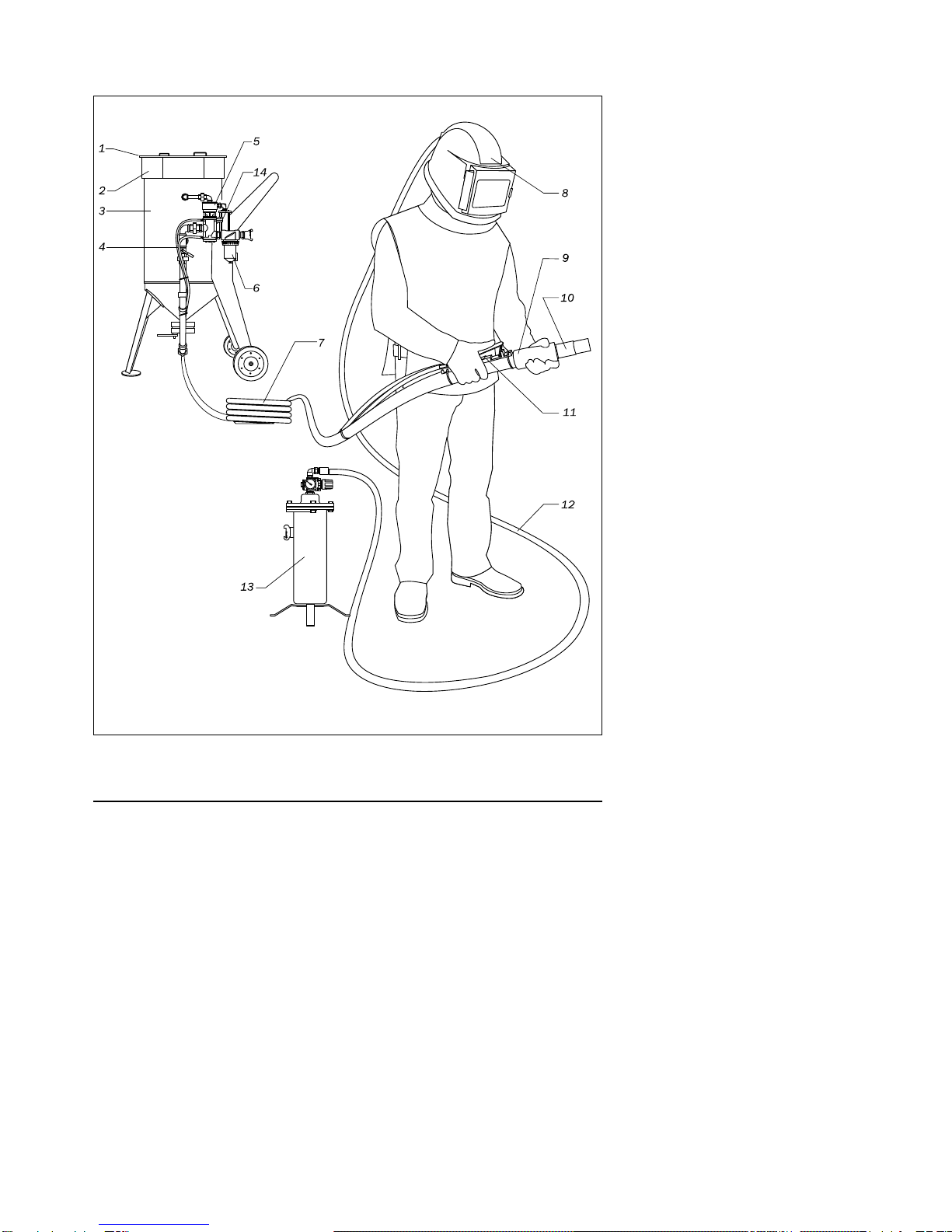
DURINGABREAKINOPERATIONALWAYSOPENSAFETYBALLVALVE14 (Fig.
2.1) ATRCVALVE, OVERAGAINSTTHEBLUELINEOF TWINHOSE(TWINLINE).
RCHANDLELEVERSHOULDBENEVERFIXEDINOPERATIONPOSITION.
SUCHFIXINGMAYCAUSEASERIOUSINJURE.
1. Turn the holder on RChandle and pressthe lever (start up). The tank is pressurized.
Onlycompressed air is expelled from the nozzle.
2. Adjust meteringvalve FSVto provide optimal air-abrasive mixture.The general rule for
abrasive blasting operations: the less abrasive you use, the better.
3. To stop operation you should release the lever (the holder automaticallyreturns to its
initial position).
4.3. Shut-down abrasive blasting operations.
1. Remove the remains of abrasive from the tank. To do this disconnect the nozzle and
point the hose into a suitable container for the abrasive remains. Turn the holder on
the RChandle and press the lever.
2. If upon completion of operation the machine isleft outsideyou should cover it with
plastic Àlm to avoid ingress of moisture into the tank.
ATTENTION!
ATSTARTUP AND SHUTDOWN ALWAYSCHECK FOR PRESENCEOF WATER
INTHEVALVEBYOPENINGUPPERBALLVALVE (Fig. 7.3). IF ALARGE
AMOUNTOFWATERISPRESENT, CHECK THEFILTER CAF-0.

11
CONTRACOR
®
DBS-25RCDBS-50RC Art. 10510/10515
5. Maintenance.
5.1. Machine maintenance.
Pop-up Valve and O-ring
replacement.
To replace the rubber pop-up
valve (2) and O-ring (1), loosen the
ring-seat (4) with аpin-wrench (5).
After havingloosened the
ring-seat, remove the old O-ring by
usinga Ànger, screwdriver, or similar
object, to work the O-ringout of the
retainer groove. Push the new O-ring
all thewaythrough the port and then
Àt it into the groove. For the last few
millimeters pull up on the rubber
O-ringand allow it to “pop” into position. Finally, reassemble the machine in reverse order.
ATTENTION!
USEONLYABRASIVEMATERIALS, APPROPRIATEFORABRASIVEBLASTING
OPERATIONS.
NEVER USEWETUNSIFTEDABRASIVEMATERIALS.
5.2. Daily maintenance.
1. Check the control valve for water presence. If water ispresent, check the CAF-0 Àlter
state.
2. Ensure that the rubber insert of the RChandle is in proper condition. If they look bad
or are worn, replace them, to avoid possible damage.
3. Ensurethat hoses and Àttings are not worn; and properlyÀxed.
3
5
4
1
2

12 CONTRACOR
®
Version 1.3
5.3. Monthlymaintenance
(or after every160 operation hours).
1. Ensure that the mufÁer and its pipe are in proper condition.
2. Ensure that there is no leak in all air connections.
3. Dismantle the control valve followingRCVUser Manual and check all movingparts.
If theylook worn, replace them, to avoid possible damage. Assemble the valve and
lubricate its movingparts with general purpose lube oil.
6. Troubleshooting.
Choking.
If neither abrasive, nor air comes out of the nozzle, relieve pressure and depressurize
the machine, then ensure that thenozzle is not choked. If onlyair without anyabrasive
comes out of the nozzle, fully open the meteringvalve, and then quicklyclose and open
again the lower ball valve of the line. If these actions do not help to relieve the pressure in
the machine, open the inspection door and ensure that there is no foreign matter in the
tank (stones, paper, etc.).
Abrasive surges.
Duringstart-up of the machine abrasive surges are normal to a certain degree.
However id abrasive surges continue, you should stabilize the abrasive Áow byquick closing
and openingof the linelower ball valve. Abrasivesurges often result from elevated moisture
content in compressed air system.Installation of additional moistureand oil separator can
solve this problem.
Wet abrasive removal.
To remove wet abrasive from machine tank you should disconnect the blasting
hose and remove rubber gaskets at machine hose coupling. Then you must fullyopen the
meteringvalve and close the lower ball valve in the machine compressed air line. With such
valve conÀguration compressed air will onlyenter the machine tank and press wet abrasive
out of the tank.

13
CONTRACOR
®
DBS-25RCDBS-50RC Art. 10510/10515
6.1. RCsystem troubleshooting.
The followinglist of checks can be used for determiningproblems in case the RC
system does not function properly:
1. Studytheinstructionsin this manual.
2. Visuallycheck all air hoses and connections to ensure that there are no air leaks.
3. Ensure that the safetyand drain valve are closed.
4. Check the RChandle for air leaks:
— when the keyis not depressed,the air should come onlyout of thebodyvent.
— when the key is depressed no air should come out of the handle.
Problem Cause Solution
Air does not come out
of the vent in the RC
handle body.
Twinline hose is clogged or
pinched. Disconnect the Twinline hose
and ensure that it isnot
clogged.
Control valve RCV
does not open. Safetydrain valve is still
open. Close the safety drain valve.
Air feed to abrasive
blastingmachine is not
sufÀcient.
Dismantle the control valve, all
parts should rotate freely.
RCcontrol valve RCV
does not close. RChandle channels are
clogged. Remove the keyand clean it.
Incorrect connection of
TWINLINEhose. Check connections and change
them if theyare incorrect.
Control valve failure. Disassemble the valve and
ensure that it functions
properly.

14 CONTRACOR
®
Version 1.3
7. SpeciÀcation
Fig. 7.1. * DBS-25RConly

15
CONTRACOR
®
DBS-25RCDBS-50RC Art. 10510/10515
Pos.
#Article Description Quantity
DBS-25RC DBS-50RC
1 10903 CFT-0 Sandblast coupling1/2” 2 2
2 10521 Nipple 1/2” (MM) 8 8
3 10565 CAF-0 Moisture separator 1/ 2” 1 1
4 10970 Remote control unit RCV 1 1
5 10522 Union with a capnut, straight, 1/2”, (FM) 2 2
6 10523 Union with a capnut, straight, 1/2”, (FF) 1 1
7 10524 T-piece, 90° , 1/ 2”, (FFF) 2 2
8 10525 Ball valve, 1/2”, (FM) 1 1
9 10526 Pipe 1/ 2” 90 mm for DBS-25RC 1 -
9 10527 Pipe 1/ 2” 190 mm for DBS-50RC - 1
10 10528 Elbow, 45° , 1/ 2” (FF) 2 2
11 10529 Pipe 1/ 2” 160 mm for DBS-25RC 1 -
11 10530 Pipe 1/ 2” 230 mm for DBS-50RC - 1
12 10531 Pipe 1/ 2” 65 1 1
13 10850 Abrasive metering valve, FSV 1 1
14 10540 Wheel for DBS-25RC 2 -
14 10541 Wheel for DBS-50RC - 2
15 10542 Screen for DBS-25RC 1 -
15 10543 Screen for DBS-50RC - 1
16 10544 Tank cover for DBS-25RC 1 -
16 10545 Tank cover for DBS-50RC - 1
17 10546 Pipe 1/ 2” 120 mm for DBS-25RC 1 -
17 10547 Pipe 1/ 2” 170 mm for DBS-50RC - 1
18 10548 Elbow, 90° , 1/2” (FF) 2 2
19 10549 Pipe 1/ 2” 100 mm 1 1
20 10532 Guide 1 1
21 15315 Pop-up valve, rubber, fоr DBS-25 / DBS-50 / CBS-25 / CBS-50 1 1
22 15316 O-Ring, rubber, fоr DBS-25 / DBS-50 / CBS-25 / CBS-50 1 1
23 15317 Seat for pop-up ring, fоr DBS-25 / DBS-50 / CBS-25 / CBS-50 1 1
24 10550 Elbow, 90° , 1/2” (FM) 3 2
25 10551 Pipe 1/ 2” 60 mm for DBS-25RC 1 -
25 10552 Pipe 1/ 2” 70 mm for DBS-50RC - 1
26 10553 Еxtension 27 mm for DBS-25RC 1 -
26 10554 Еxtension 40 mm for DBS-50RC - 1
27 10828 RCBall valve, 1/4” 1 1
28 10880 DMH remote control handle 1 1
29 - Remote control hose, mounted with Àttings, 0,8 m 1 1
30 12105 Remote control hose, mounted with Àttings, 5m 1 1

16 CONTRACOR
®
Version 1.3
8. Instructions for Use Pressure Vessel
of Abrasive Blasting Machine
CONTRACOR DBS.
8.1. Technical Parameters.
Vessel Type DBS– 25 -10 DBS– 50 -10
Volume V(L) 25 50
Calculated Pressure P(Bar) 10 10
Maximum WorkingPres-
sure PS(Bar) 10 10
Maximum Test Pressure PT(bar) 14,3 14,3
Minimal OperatingTempe-
rature TSmin (°C) -10 -10
Maximum OperatingTem-
perature TSmax(°C) 50 50
Corrosion charge c
2
(mm) 0,5 0,5
Media air + abrasive ma-
terials air + abrasive ma-
terials
31 12401 FTL-M Fitting,1/ 4” (M) xhose end 6 mm, for Twinline RChose 6 6
32 12402 FTL-FFitting, 1/ 4” (F) xhose end 6 mm for Twinline RC-hose 2 2
33 50051 Hose clamp 10 -16 mm 8 8

17
CONTRACOR
®
DBS-25RCDBS-50RC Art. 10510/10515
8.2. Field of Application.
The pressure vessels are intended for use onlywith the media and within the parame-
ters stated in the table above. The use for anyother purpose is not allowed.
8.3. Set Up and Installation.
1. The vesselscan beset upindoorsor outdoorsunder a roof.
Safety-regulations and standards and Àre-regulations and standards, dependingon
the media used,must beobserved when choosinga place for setup.When set up
outdoors, the minimal and maximum workingtemperatures must be observed.
2. The vessels have to be installed in such a way that they and all Àttings and parts are
accessible for inspections, tests, maintenance and cleaning, from the inside and the
outside.
The type platehas tobeaccessibleand kept clean so that it is readable at all times.
3. The main bodyis based on supports, stands or feet suitable for the strain of the
pressure test. The vessel must be set up on foundations with a stabilitysuitable for
the strain of the pressure test.
8.4. Setting the Vessel to Work.
A. Conditions for setting the vessel to work.
1. The vessel can be set to work, includingtest operation, if:
— its condition doesnot posea danger to people and environment,
— the system and equipment is complete, tested and meets the requirements
accordingto the documentation and applyingstandards.
B. Procedure before start up of the machine
2. Before closingthe vessel make sure that there is no foreign matter or object inside.
3. Makesure that all inspection doors and Áanges have the correct number of bolts,
that the bolts areinserted correctlyin place and of the right length and tightened to
the correct torque.

18 CONTRACOR
®
Version 1.3
C. Start up Procedure.
4. If not stated otherwise in the instructions for the start up of the vessel, the control
valve must open in such a waythat the pressure does not rise more than 5 bar per
minute and the temperature does not exceed the value stated for the start up of the
vessel. Avoid sudden changes in pressureor temperature as theycan cause unfavou-
rable tension.
5. Always watch the vessel, valvesand Àttings duringthe start up of the system. If a
problem occurs, e.g. leaks or cracks, the vessel has to be closed down immediately.
6. During transport vessels must not be under pressure andtheymust not contain
media.
7. When the workingpressure is built up, check the vessel and its attachments for
leaks.
D. Operation of the vessels.
8. The vessel must be closed down immediately,
— if cracksappear,
— if there is a leak in a connection that can bedisassembled,
— if thereisa safety-equipment failureor defect (e.g. cloggingof thesafetyvalve)
or a failureof the level meter etc.,
— whenthereis immediatedanger of an accident or a problem if operation conti-
nue,
— if anyother unusual phenomena occur duringoperation whosecauses cannot
befound or eliminated,
— if a deformation on the vessel wall occurs,
— if the temperature exceeds the maximum workingtemperature,
— in all cases stated in the manual that advisethe operator to do so.

19
CONTRACOR
®
DBS-25RCDBS-50RC Art. 10510/10515
8.5. Operating the Vessel.
1. Onlypersons meetingthe followingrequirements are allowed to operate the vessel:
— The person is of age and able to dosuch work,
— The person knows the applyingregulationsand rulesfor the operation of the
vessel well, has been trained practicallyand haspassed a correspondingexam
which is documented bya certiÀcate.
A. Duties and responsibilities of the operator
2. The person appointed to operate the vessel is obliged to:
— know all facilitiesand equipment securinga safe operation, and their use, well
and be able to react appropriatelyin unusual circumstances to restore safety,
— report everyproblem, damage or unusual incidents, occurring during operation
of thevessel or its attachments, tohis superior immediatelyandclose down the
vessel if further operation could bedangerous,
— take part in checks and inspectionsof the vessel, sothat he knows the conditi-
on of the vessel,
— check and test the equipment asrecommended,
— document the operation according to the regulations,
B. Vessel Inspections and Tests
3. The vessels have to be subjected to the followingtests and inspections:
— External inspection duringoperation,
— Inspection of interior,
— Leak test,
— Pressure test ,
The tests must be conducted accordingto the applying regulations for the use
of pressure equipment of the respective countrythat the vessel is used in.

20 CONTRACOR
®
Version 1.3
C. Documentation of Inspections.
4. The results of the inspectionsand tests are recorded in an inspection log, Àlled in on
inspection cards or an inspection-certiÀcate is written. The inspection loghas to be
kept with the user and available duringthe whole period of use of the vessel.
8.6. Cleaning and Maintenance of Vessels.
1. The cleaningmethod and media have to be in such a waythat theydo not to damage
the wallsof the vessel or endanger the workers.
2. The vessel must be cleaned inside and outside and it must be covered with a suitable
layer of paint that protects it from inÁuences of the operatingmedia and external
inÁuences.
3. Onlyspeciallytrained and experienced persons are allowed to work on the vessel and
the system components, including the safetyequipment. They have to be appointed
with their namesput down and theyhave to knowtheregulationsin this Àeld of work.
8.7. Repair of Vessels.
It is not allowed to weld or work on the parts of the vessel that are subject to pressu-
re. Onlyauthorized organizations are allowed to install or repair the vessels.
This manual suits for next models
1
Table of contents
Languages:
Other Contracor Shot Blasting Machine manuals

Contracor
Contracor CAB-110S Operating instructions

Contracor
Contracor BlastRazor Z-25RC User manual

Contracor
Contracor BlastRazor Z-100RC User manual

Contracor
Contracor DBS-100 User manual

Contracor
Contracor DBS-100RC User manual

Contracor
Contracor CAB-110P User manual

Contracor
Contracor BlastRazor Z-100RCS User manual